fuel type JAGUAR X308 1998 2.G User Guide
[x] Cancel search | Manufacturer: JAGUAR, Model Year: 1998, Model line: X308, Model: JAGUAR X308 1998 2.GPages: 2490, PDF Size: 69.81 MB
Page 1189 of 2490
E
lectronic Engine Controls -
Electronic Engine Controls
D
iagnosis and Testing
I
nspection and Verification
1.
1. Veri
fy the customer concern.
2. 2. Confirm which, if any, warning li ghts and/or messages were displayed on the instrument cluster.
• NOTE: If any warning lights and/or me ssages were displayed when the fault occurred, refer to the Driver Information
table for DTCs associated with the display, then to the DTC index table for possible sources and actions. Some warnings will
appear to clear when the ignition is cycl ed. This is often because the warning has flagged as a resu lt of one of the vehicle's
on-board diagnostic routines having run to detect the fault. If the same routine is not run when the ignition is switched ON,
the warning will not reflag until the routine does run. See the DTC summaries for drive cycle routines.
3. 3. Visually inspect for obvious signs of mechanical or electrical damage.
V
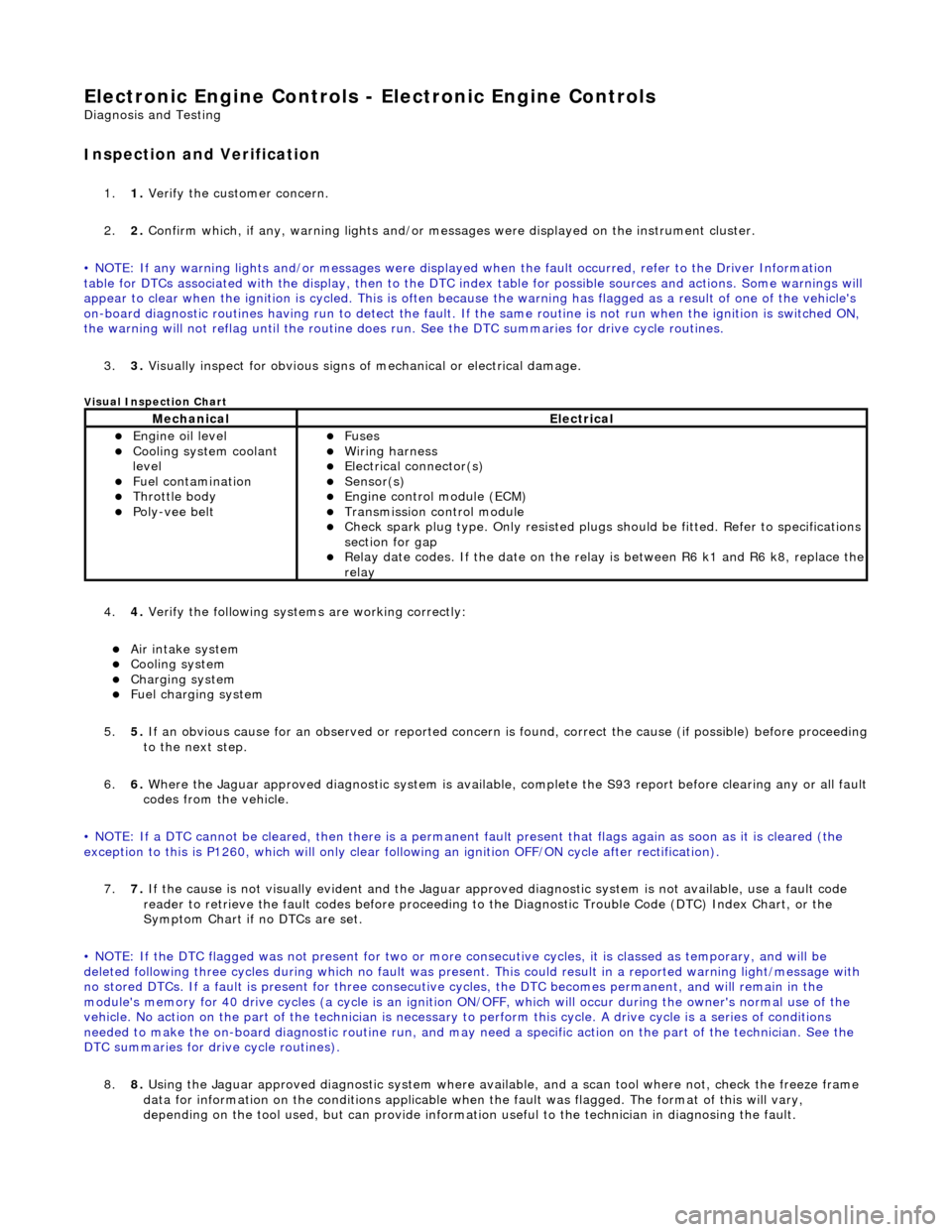
isual Inspection Chart
4.
4. Veri
fy the following syst
ems are working correctly:
Air in
take system
Coo
ling system
Charging system
F
uel charging system
5. 5. If an obvious cause for an observed or reported concern is found, correct the cause (if possible) before proceeding
to the next step.
6. 6. Where the Jaguar approved diagnostic sy stem is available, complete the S93 report before clearing any or all fault
codes from the vehicle.
• NOTE: If a DTC cannot be cleared, then there is a permanent fault present that flag s again as soon as it is cleared (the
exception to this is P1260, which will only clear following an ignition OFF/ON cycle after rectification).
7. 7. If the cause is not visually evident and the Jaguar approv ed diagnostic system is not available, use a fault code
reader to retrieve the fault codes be fore proceeding to the Diagnostic Trou ble Code (DTC) Index Chart, or the
Symptom Chart if no DTCs are set.
• NOTE: If the DTC flagged was not present for two or more co nsecutive cycles, it is classed as temporary, and will be
deleted following three cycl es during which no fault was present. This could result in a reported wa rning light/message with
no stored DTCs. If a fault is present for three consecutive cycles, the DTC becomes permanent, and will remain in the
module's memory for 40 drive cycles (a cy cle is an ignition ON/OFF, which will occur during the owner's normal use of the
vehicle. No action on the part of the technician is necessary to perform this cycle. A drive cycle is a series of conditions
needed to make the on-board diagnostic ro utine run, and may need a specific action on the part of the technician. See the
DTC summaries for driv e cycle routines).
8. 8. Using the Jaguar approved diagnostic system where available, and a scan tool where not, check the freeze frame
data for information on the conditions applicable when the fault was flagged. The format of this will vary,
dependin
g o
n the tool used, but can provide information useful to the technician in dia
gnos
in
g th
e fault.
MechanicalElectrical
Engi
ne oil level
Coo
ling system coolant
level
Fuel contamination
Throttle body Poly
-vee belt
F
uses
W
iring harness
E
lectrical connector(s)
Sens
or(s)
Engine
control module (ECM)
Tran
smission control module
Check spark plu
g type. Only re
sisted plugs should be fitted. Refer to specifications
section for gap
Relay date codes.
If the date on the rela
y is between R6 k1 and R6 k8, replace the
relay
Page 1690 of 2490
Fuel System - General Information - Fuel System Pressure Rele
ase
Gen
e
ral Procedures
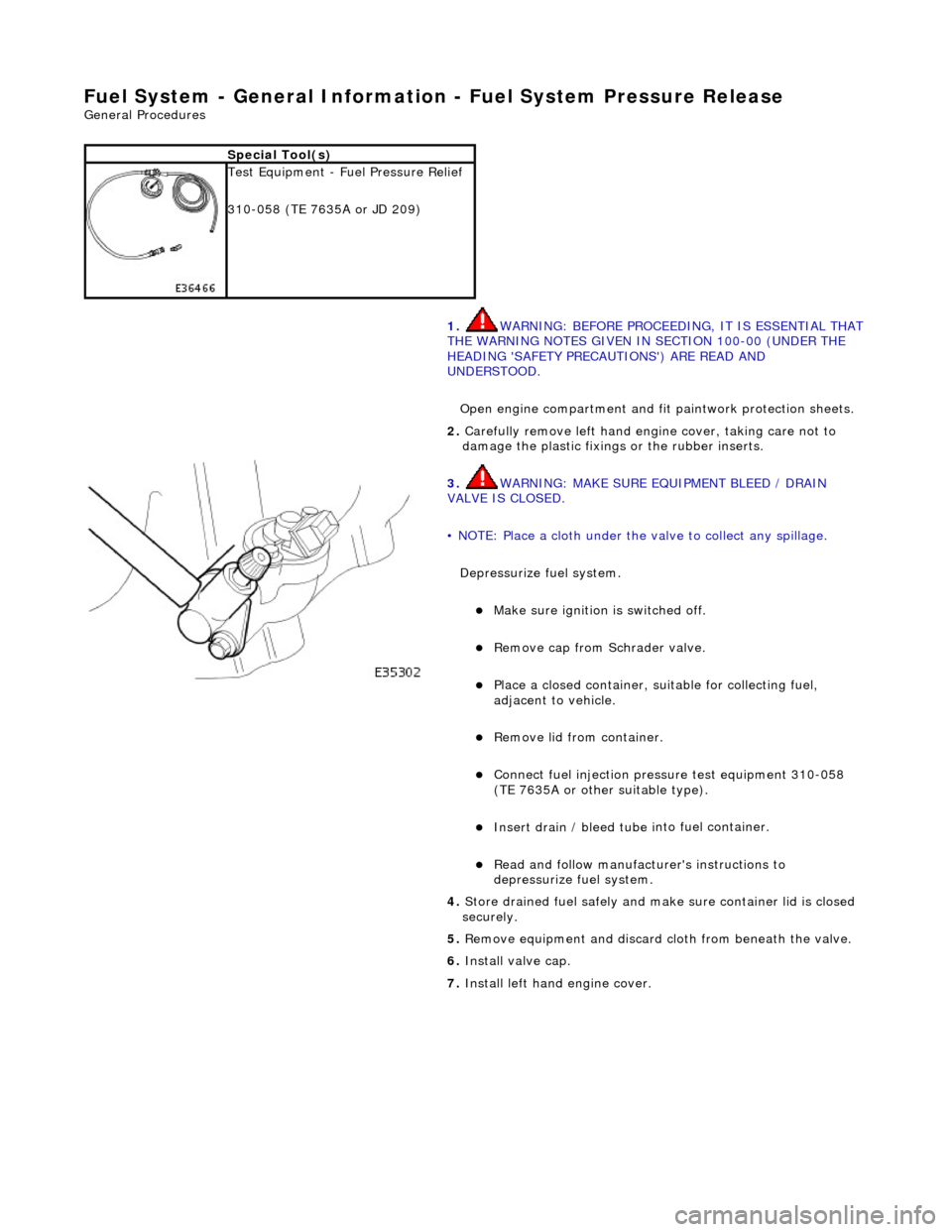
S p
ecial Tool(s)
Tes
t
Equipment - Fuel Pressure Relief
310-058 (TE 7635A or JD 209)
1. WARNING: BEFORE PROCEEDING, IT IS ESSENTIAL THAT
THE WARNING NOTES GIVEN IN SECTION 100-00 (UNDER THE
HEADING 'SAFETY PRECAUTIONS') ARE READ AND
UNDERSTOOD.
Open engine compartment and fi t paintwork protection sheets.
2. Carefull
y remove left
hand engine cover, taking care not to
damage the plasti c fixings or the rubber inserts.
3. WA
RNING: MAKE SURE EQUIPMENT BLEED / DRAIN
VALVE IS CLOSED.
• NOTE: Place a cloth under the valve to collect any spillage.
Depressurize fuel system.
Make sure ignition i s
switched off.
R
e
move cap from Schrader valve.
Pla
c
e a closed container, su
itable for collecting fuel,
adjacent to vehicle.
R e
move lid from container.
Conne
ct
fuel injection pressu
re test equipment 310-058
(TE 7635A or other suitable type).
Insert drain / bleed tu be i
nto fuel container.
R
e
ad and follow manufacturer's instructions to
depressurize fuel system.
4. Store drained f u
el safely and make
sure container lid is closed
securely.
5. Remove equipment and discard cloth from beneath the valve.
6. Install valve cap.
7. Install left hand engine cover.
Page 1691 of 2490
Fuel System - Gener
al Information - Fuel Tank Draining
Gen
eral Procedures
1.
WARNING: BEFORE PROCEEDING, IT IS ESSENTIAL THAT
THE WARNING NOTES GIVEN IN SECTION 100-00 (UNDER THE
HEADING 'SAFETY PRECAUTIONS') ARE READ AND
UNDERSTOOD.
Remove the battery. Refer to operation 86.15.01.
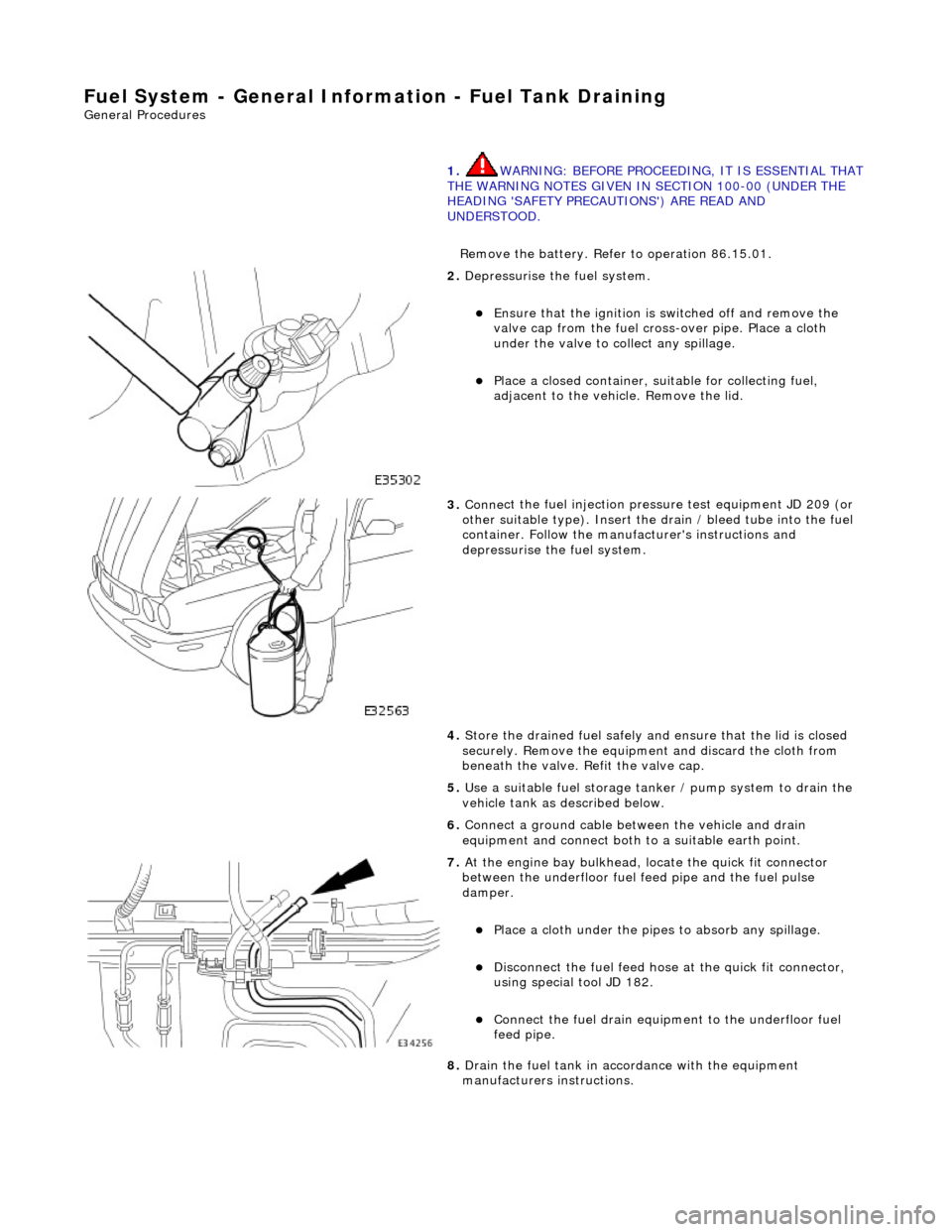
2. De
pressurise the fuel system.
E
nsure that the ignition is
switched off and remove the
valve cap from the fuel cross-over pipe. Place a cloth
under the valve to collect any spillage.
Pla
ce a closed container, su
itable for collecting fuel,
adjacent to the vehicle. Remove the lid.
3. Conne
ct the fuel injection pressu
re test equipment JD 209 (or
other suitable type). Insert the drain / bleed tube into the fuel
container. Follow the manufa cturer's instructions and
depressurise the fuel system.
4. Store the drained fuel safely and ensure that the lid is closed
securely. Remove the equipmen t and discard the cloth from
beneath the valve. Refit the valve cap.
5. Use a suitable fuel storage tank er / pump system to drain the
vehicle tank as described below.
6. Connect a ground cable betw een the vehicle and drain
equipment and connect both to a suitable earth point.
7. At the engine bay bulkhead, lo cate the quick fit connecto
r
between the underfloor fuel feed pipe and the fuel pulse
damper.
Pla
ce a cloth under the pipes
to absorb any spillage.
D
isconnect the fuel feed hose
at the quick fit connector,
using special tool JD 182.
Conne
ct the fuel drain equipment to the underfloor fuel
feed pipe.
8. Drain the fuel tank in accordance with the equipment
manufacturers instructions.
Page 1692 of 2490

Fuel Tank and Lines - Fuel Tank and Li
nes
Description an
d Operation
Fuel Tank
Parts List
The steel fuel tank is located inside the trunk and mounted across the vehicle behind the passenger compartment bulkhead.
The fuel tank is held in posi tion by two retaining straps fi tted to body-mounted brackets.
The fuel tank has an integral non-adjustable fill er pipe and integral breather and vapor pipework.
A single fuel pump is mounted inside the tank on vehicles with normally aspirated engines. For vehicles with supercharged
engines, two pumps are fitted in the tank. Fuel is drawn by the pump(s) from the fuel tank and supplied via the fuel lines
and 70 micron filter to the fuel rails.
The fuel lines run from front-to-rear down the vehicle's left-hand-side.
Ite
m
Part
Number
Descr
iption
1—Fu
el filler latch box
2—Pressure reli
ef pipe, ORVR
(shown) / tank breather pipe on non-ORVR systems
3—Tank grounding
cable
4—Evaporative flan
ge assembly
(ORVR type shown)
5—Trunk elec
trical harne
ss (part of)
6—Fue
l
level sensor
flange/connector
7—Fu
el tank retaining straps
8—F
u
el tank retaining stra
ps adjustable clamps
9—Fu
el tank retaining straps lower brackets
10—Tank vapor outlet pipe to un
derflo
or pipe quick-fit connector
11—F
u
el filler latch bo
x water drain pipe
Page 1693 of 2490

Filler Cap and P
ipe
The fuel
filler cap with bayonet-type fixi
ng is located beneath a remote-release sp ring-latched lid on the rear saddle panel
on the left-hand-side of the vehicle.
Fuel Pum
p
The fu
el pump(s) is energized by an ECM co
ntrolled relay. Fuel is drawn by this pu mp and supplied to the fuel injectors via
the fuel line, filter and fuel rails.
Servicing of the fuel pump re quires fuel tank removal.
Ev
aporative Loss Flange Assembly
The evaporative-loss flan
ge asse
mbly is mounted centrally on top of the tank. The flange assembly consists of a removeable
steel cap which mounts the evaporative emissions system vapor outlet valves and, if applicable, a pressure sensor. The
external electrical supply to th e fuel pump(s) is also made via a connector on the flange.
The flange assembly is fixed to the tank by a locking ring which is turned usin g special tool JD-174. A seal is fitted between
the flange assembly and the tank. Three di fferent flange assemblies are applicable according to the evaporative emission
system fitted to the vehicle. The fl ange size and fixing are identical fo r the three systems, as described.
Removal of the evaporative flange assembly is necessary to gain access to th e fuel pump(s) and other internal components.
To remove the evaporative fl ange assembly the fuel tank must first be removed.
The evaporative flange variant assemblies are described, together with service information, in Section 303-13.
Fuel R
eturn
Excess fuel
is directed back to
the fuel tank via a return line.
Fuel Pum
p Relay
The
fuel pump relay,
under control of the ECM, switches power to the fuel pump motor.
I
nertia Fuel Shutoff (IFS) Switch
The IF
S switch is located in the right-hand
side footwell behind the footboard carpet . When activated the switch isolates the
ignition system and fuel pump, releases any locked doors and disables unnecessary electrical systems. The system can be
reset by pressing down the flexible cover on the top of the switch.
• NOTE: The doors will not unlock if the IFS switch is tripped when the ignition switch is in position '0'.
Page 2022 of 2490
Body closures
Each front and rear door consists of a welded, mild steel inner frame and an outer panel. The outer panel is welded to the
waist rail and cheater of the inner frame, then bonded and clinched to fo rm the door assembly. Cosmetic PVC bead is
applied to all clinch joints. Sp onge rubber seals are mounted on the doors. Inte rnal insulation is provided by a foam water
shedder attached to the door by double-sided adhesive tape.
The door aperture B/C posts are reinforced over their full height to fully satisfy all forthcoming European and Federal side
impact legislation. The hood consists of one piece inner and outer panels clinched and bonded together, with cosmetic bead
PVC sealant applied to all clinch joints. Th e hood pivots at the front on two hinges each secured by bolts to the hood front
underside and the BIW front upper crossmem ber. Two gas struts secured to the hood by pivot pins and snap-on couplings,
support the hood in the open position. A full width insulating pad is secured by screws to the underside of the hood. A
sponge rubber tubular seal is mounted tran sversely towards the front of the hood underside. The trunk lid is of similar
construction to the hood, consisting of inner and outer pa nels clinched and bonded together and PVC bead sealed.
Incorporating a removable moulded liner and two trunk illuminati on lights, the trunk lid is supported when open, by two gas
struts, each secured to the inner wheel arch and trunk hinge by snap fittin gs. For some markets, a warning triangle is
attached to a bracket on the trunk lid underside and is retained in the open position by a rubber block.
Fascia
One-piece slush-moulded fascia on inject ion moulded armature and steel cross-rail reinforcement. Fascia support brackets
set with BIW to achieve close tolerance fit of fascia to bo dy eliminate necessity for adjustment following removal and
installation..
Fuel Filler Flap
The fuel filler comprising a hinged flap attached to the body decking panel by tw o nuts, incorporates a rubber buffer, snap-
in striker, hinge spring and fuel cap stowage magnet. The rubber fuel bowl moulding is attached via a steel armature to the
body reinforcement panel by five M5 nuts and is retained at the filler neck by a clip. The mating drain tube is fitted with an
internal filter. The fuel filler flap latch mechanism attached to the fuel bowl armatu re by two M5 nuts, includes a locking pin
and actuator which are both se rviceable items. The latch actuator operates independently from the central locking system;
it is driven directly by the se curity and locking control module. Locking of the fuel filler flap is achi eved only by operation of
the key or by the remote rf transmitter.
Seating
All front seats are equipped with electric height adjustment. In addition, both seats are available with manual or power
forward and rearward adjustment, manual or power operated headrest adjustment, 12 way electric adjustment, memory
controlled 12 way seat adjustment and integral seat heating. A side air bag module is installe d in the outboard squab wing
of each front seat. Each front seat has a non-handed, one-piece frame incorporatin g cushion and squab frames, side air bag
support bracket and seat adjuster mechanis ms. Seat switchpacks are installed on the outboard side of driver and passenger
seats and control modules are installed in the base of each seat . The standard rear seat is of fixed, bench type with full
width removable cushion. For certain mark ets, two individual rear seats are available as an option on long wheelbase
models. Both type s of rear seat are available with th ermostatically controlled heating of the cushion and sq uab. Individual
rear seats are electrically adjustable fo r squab re cline (via cushion fore and af t movement), head restraint height and
lumbar support. Separate motors provide ad justment of each seat cushion and head restraint and an electrically driven air
compressor provides variation of lumbar support. Seat adjustment is controlled via switches installed on a panel in an
extension to the centre console.Both the driver and front pass enger seat are secured to the vehicle floor at four points.
Interior Trim
The one-piece door casings are trimmed in UEV to match the seating, with wood veneer at the waistline and a carpet insert
at the front lower corner. Each casing is secured to the door inner panel by fir tree fastener s along the lower section, two
armrest fixings at the centre and veneer panel dowels and fixings at the top. The armrests which are common to front and
rear doors, are trimmed in matc hing leather or UEV according to specification. Switchpacks dedicated to driver and front or
rear passenger, are incorporated in the ar mrests. A speaker is installed in the lower section of each door and a tweeter is
incorporated behind each interior door handle escutcheon. where premium ICE is fitted, the front tweeters are installed in
the upper A posts. On each side, a graine d UEV finisher trimmed to match the head lining is secured to the 'A' post and
cantrail by fir tree fasteners locating in BIW apertures. Th e upper 'D' post finisher is trimmed and secured in the same
manner. The single piece'B' post finishers, also finished in grained matching UEV, each have a front seat belt exit aperture
and are secured to the BIW by four spring clips and two fir tree fasteners. The one-piece headlining consists of a 6mm thick
polyurethane foam membrane covered with suede effect knitted polyester. The headlining is secured to the BIW roof by
body tangs, the roof console, sun visors, combined grab handles and coat hooks, th e cantrail finishers and where fitted, the
Page 2023 of 2490
sliding roof finisher and clips. Carpet covered trims line the trunk and are secured by fir tree fasteners to the sides and fro nt inner panel.
Rear View Mirrors
The.interior rear view mirror is an electrochromic unit that automatically da rkens to prevent glare from following vehicle
lights. This automatic function is selected by pressing the switch at the bottom of the mirror. Pressing the switch again
cancels this function. An LED then illuminates when automatic dipping is operative. The light sensing unit for the Night
Sentinel automatic lamp operating system is also incorporated in the mirror casing.
The door mirrors are cheater mounted, colo r-keyed units, remote electrically adjustable and heated. Adjustment of both
mirrors is carried out from the driver's door switchpack.A slider switch selects the mirror to be adjusted, and a disc switch
adjusts the selected mirror to the required position. Mirror ad justment can only be made when the ignition switch is in
position I or II or the driver's door is open, and the selector switch is moved from the central position. The door mirrors also
automatically darken under control of the electrochromic interior rear view mirror. Mirror heating elements operate on
selection of backlight heating.
Automatic dipping of passenger door mirror for kerb view when reversing, is fitted as part of the memory pack. With the
ignition switch in position II, the mirror selector switch in the left or right position and reverse gear selected, automatic
dipping is initiated by moving the mirror toggle switch rearwards and releasing. On receipt of the dip signal, the passenger
door mirror is driven downwards either 7 degrees, bottom of travel, or 4,5 to 5,5 seconds, whichever occurs first.
Subsequent rearward movement of the toggle switch achieves further dipping of the mirror in the same increments and
sequence. The mirror can be manu ally returned to the normal memorised positi on by moving the toggle switch forward with
reverse gear selected. The mirror will auto matically return to memorised position on deselection of reverse gear, or moving
ignition switch from position II.
Door mirror fold-back where fitted, to facilitate parking in conf ined spaces, can be initiated when the ignition switch is in
position I or II, the mirror selector switch is in the centra l position and vehicle speed is below 19 km/h (12 mph). Mirror
fold-back is then initiated by moving the toggle switch rear wards and releasing it. The door mirrors are returned to the
normal driving position by agai n moving toggle switch rearwards. There is no speed constraint on this operation. In the
event of a fold-back mirror becoming 'out of position' due to acci dental impact, it must only be re-positioned by initiating
the fold-back sequence.
Loss of power supplies will result in loss of mirror fold-back memory. In the event of such a memory loss with mirrors in the
normal position, fold-back will operate on second movement of the toggle swit ch. On loss of memory with mirrors in the
fold-back position, they will return to the no rmal position on next fold-back operation.
Bumpers
Each bumper comprises a beam mounted to the body via two strut assemblies, and a moulded polypropylene cover
incorporating side armatures and chrome plated blades. Each strut is secured to the BIW by three bolts and supports the
beam on a single bolt/height adjuster. The front bumper cover which is moulded to form a lo wer air intake for the cooling
pack, also incorporates left and right handed twin fog lamps, brake coolin g ducts. Side marker lamps fitted for some
markets serve only as reflectors for UK and Europe. A plastic undertray secured to the lower edge of the front bumper,
improves airflow and minimises the ingres s of road grime in that area. Standard bumpers have glass mat thermoplastic
(GMT) beams mounted on GMT struts. For certain markets, aluminium bumper beams are installed on menasco energy
absorbing struts. Whilst both types of front bumper provide a fu lly integrated 'soft front end' that satisfies bumper impact
requirements, the energy absorbing front and rear bumpers are further designed to withstand 5mph (8kph) impacts with no
visible damage sustained. Side markers/re flectors, and direction indicators are designed for ease of ac cess from the outside
of the bumper. For adjustment and bulb change, the fog lamps are accessed from th e bumper interior. The bumper covers
are body coloured and matched. Replacement covers are supplied complete with side armatures and are finished in primer
Trunk
The trunk houses the spare wheel, the battery, an electrical carrier containing electrical fuses, relays and modules and a
compact disc auto-changer attached to body bracketry. The trun k is fitted with push-fit liners to the sides and front inner
panel.The carpet covered floor is in two removable sections, one covering the spare wheel and wheel changing equipment,
the other covering the battery and electrical carrier. The front and rear edges of the floor board loca te in blocks on the fuel
tank backboard and the rear of the body , which provide two height settings to accommodate the difference in thickness
between the space saver and full sized spare wheels. A moulded finisher covering the rear of the trunk below the sill is
secured to the rear panel by tabs and fir tree fasteners. Finisher panels fitted over the rear lamp units provide for access
from the trunk. Finisher panels fitted to the rear lamp units provide trunk inte rior access to the lamps. The trunk lid
underside is fitted with a removable mo ulded liner and two trunk illumination light s. Trunk locking is based on a central
latch and striker, operated electrically through the central lo cking system by an adjacent actuator or by key in a barrel lock