window JAGUAR X308 1998 2.G User Guide
[x] Cancel search | Manufacturer: JAGUAR, Model Year: 1998, Model line: X308, Model: JAGUAR X308 1998 2.GPages: 2490, PDF Size: 69.81 MB
Page 2009 of 2490
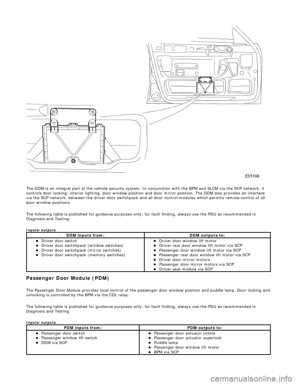
The DDM is an integral part of the vehi cle security system. In conjunction with the BPM and SLCM via the SCP network, it
controls door locking, interior lighting, door window position and door mirror position. The DDM also provides an interface
via the SCP network, between the driver door switchpack and all door control modules which permits remote control of all
door window positions.
The following table is published for guidance purp oses only; for fault finding, always use the PDU as recommended in
Diagnosis and Testing:
Inputs/outputs
Passenger Door Module (PDM)
The Passenger Door Module provides local control of the pass enger door window position and puddle lamp. Door locking and unlocking is controlled by the BPM via the CDL relay.
The following table is published for guidance purp oses only; for fault finding, always use the PDU as recommended in
Diagnosis and Testing:
Inputs/outputs
DDM inputs from:DDM outputs to:
пЃ¬Driver door switch пЃ¬Driver door switchpack (window switches) пЃ¬Driver door switchpack (mirror switches) пЃ¬Driver door switchpack (memory switches)
пЃ¬Driver door window lift motor пЃ¬Driver rear door window lift motor via SCP пЃ¬Passenger door window lift motor via SCP пЃ¬Passenger rear door window lift motor via SCP пЃ¬Driver door mirror motors пЃ¬Passenger door mirror motors via SCP пЃ¬Driver seat module via SCP
PDM inputs from:PDM outputs to:
пЃ¬Passenger door switch пЃ¬Passenger window lift switch пЃ¬DDM via SCP
пЃ¬Passenger door actuator unlock пЃ¬Passenger door actuator superlock пЃ¬Puddle lamp пЃ¬Passenger door window lift motor пЃ¬BPM via SCP
Page 2010 of 2490
Driver Rear Door Module (DRDM)
The Driver Rear Door Module provides local control of the driver rear door window position and puddle lamp. Door locking
and unlocking is controlled by the BPM via the CDL relay.
The following table is published for guidance purp oses only; for fault finding, always use the PDU as recommended in
Diagnosis and Testing:
Inputs/outputs
Passenger Rear Door Module (PRDM)
The Passenger Rear Door Module provides local control of th e passenger rear door window position and puddle lamp. Door
locking and unlocking is controlled by the BPM via the CDL relay.
The following table is published for guidance purp oses only; for fault finding, always use the PDU as recommended in
Diagnosis and Testing:
Inputs/outputs
Roof Console Switch Module (RCSM)
DRDM inputs from:DRDM outputs to:
пЃ¬Driver rear door switch пЃ¬Driver rear window lift switch пЃ¬DDM via SCP
пЃ¬Driver rear door actuator unlock пЃ¬Driver rear door actuator superlock пЃ¬Puddle lamp пЃ¬Driver rear door window lift motor пЃ¬BPM via SCP
PRDM inputs from:PRDM outputs to:
пЃ¬Passenger rear door switch пЃ¬Passenger rear window lift switch пЃ¬DDM via SCP
пЃ¬Passenger rear door actuator unlock пЃ¬Passenger rear door actuator superlock пЃ¬Puddle lamp пЃ¬Passenger rear door window lift motor пЃ¬BPM via SCP
Page 2034 of 2490
Body Closures - Body Closures
Description and Operation
Front and Rear Doors
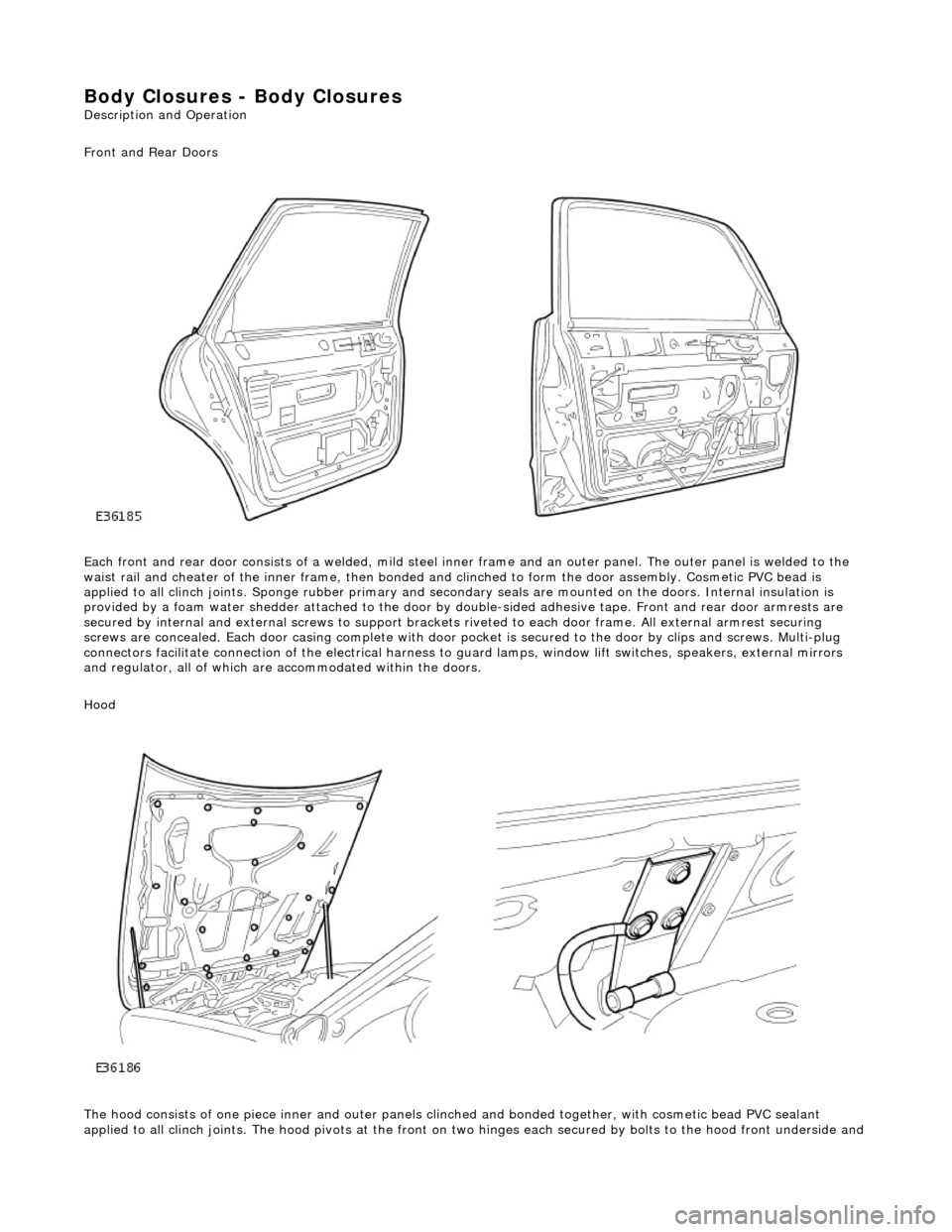
Each front and rear door consists of a welded, mild steel inner frame and an outer panel. The outer panel is welded to the
waist rail and cheater of the inner frame, then bonded and clinched to fo rm the door assembly. Cosmetic PVC bead is
applied to all clinch joints. Sponge rubber primary and secondary seals are mo unted on the doors. Internal insulation is
provided by a foam water shedder attached to the door by double-sided adhesive tape. Front and rear door armrests are
secured by internal and external screws to support brackets riveted to each door frame . All external armrest securing
screws are concealed. Each door casing complete with door po cket is secured to the door by clips and screws. Multi-plug
connectors facilitate connection of the electrical harness to guard lamps, window lift switches, speakers, external mirrors
and regulator, all of which are accommodated within the doors.
Hood
The hood consists of one piece inner an d outer panels clinched and bonded toge ther, with cosmetic bead PVC sealant
applied to all clinch joints. The hood pivo ts at the front on two hinges each secured by bolts to the hood front underside and
Page 2061 of 2490
Interior Trim and Ornamentation - Door Window Control Switch Finish
Panel
Removal and Installation
Removal
Installation
1.
Remove door casing veneer panel. Refer to 76.47.11.
2. Remove door casing. Refer to 76.34.01.
3. Remove door armrest and remo ve switchpack assembly from
armrest. Refer to 76.34.22.
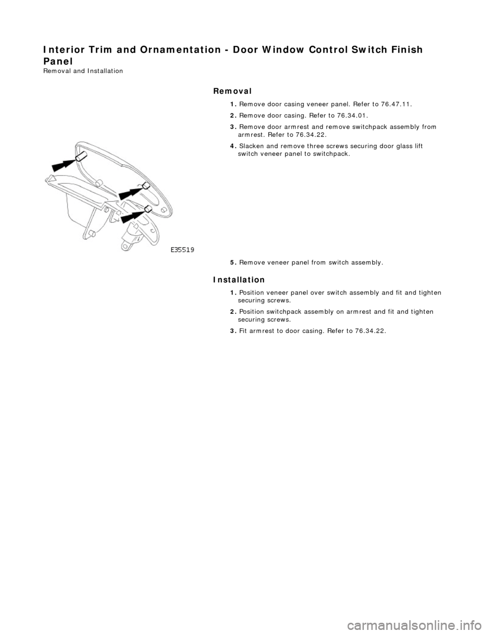
4. Slacken and remove th ree screws securing door glass lift
switch veneer panel to switchpack.
5. Remove veneer panel from switch assembly.
1. Position veneer panel over swit ch assembly and fit and tighten
securing screws.
2. Position switchpack assembly on armrest and fit and tighten
securing screws.
3. Fit armrest to door casing. Refer to 76.34.22.
Page 2076 of 2490

Interior Trim and Ornamentation - Headliner
Removal and Installation
Removal
Vehicles with roof opening panel
All vehicles
1. Remove the roof opening panel trim.
For additional information, refer to: Roof Opening Panel Trim
(501-17 Roof Opening Panel, Removal and Installation).
2. Remove both C-pill ar trim panels.
For additional information, refer to: C
-Pillar Trim Panel (501-05
Interior Trim and Ornamentatio n, Removal and Installation).
3. Remove both A-pill ar trim panels.
For additional information, refer to: A
-Pillar Trim Panel (501-05
Interior Trim and Ornamentatio n, Removal and Installation).
4. Remove the overhead console.
For additional information, refer to: Overhead Console
(501-12
Instrument Panel and Console, Removal and Installation).
5. Remove the rear window glass.
For additional information, refer to: Rear Window Glass
(501-
11 Glass, Frames and Mechanis ms, Removal and Installation).
6. Disconnect the anti-theft se nsors electrical connector.
7. CAUTION: With the aid of an other technician, support the
headliner to ensure it is not folded or creased during removal.
Remove both sun visors.
For additional information, refer to: Sun Visor
(501-05 Interior
Trim and Ornamentation, Re moval and Installation).
8. NOTE: Left-hand shown, right-hand similar.
Detach the retaining screw cove r from the headliner retaining
trim.
9. NOTE: Left-hand shown, right-hand similar.
Remove the headline r retaining trim.
Page 2079 of 2490

Vehicles with roof opening panel
7. Install both sun visors.
For additional information, refer to: Sun Visor (501-05 Interior
Trim and Ornamentation, Re moval and Installation).
8. Install the rear window glass.
For additional information, refer to: Rear Window Glass
(501-
11 Glass, Frames and Mechanis ms, Removal and Installation).
9. Fit the electrical connectors into the retaining clips at the
overhead console location.
10. Install the overhead console.
For additional information, refer to: Overhead Console
(501-12
Instrument Panel and Console, Removal and Installation).
11. Install both C-pillar trim panels.
For additional information, refer to: C
-Pillar Trim Panel (501-05
Interior Trim and Ornamentatio n, Removal and Installation).
12. Install both A-pillar trim panels.
For additional information, refer to: A
-Pillar Trim Panel (501-05
Interior Trim and Ornamentatio n, Removal and Installation).
13. Install the roof opening panel trim.
For additional information, refer to: Roof Opening Panel Trim
(501-17 Roof Opening Panel, Removal and Installation).
Page 2095 of 2490
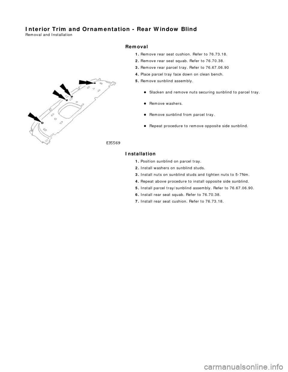
Interior Trim and Ornamentation - Rear Window Blind
Removal and Installation
Removal
Installation
1.
Remove rear seat cushion. Refer to 76.73.18.
2. Remove rear seat squa b. Refer to 76.70.38.
3. Remove rear parcel tray. Refer to 76.67.06.90
4. Place parcel tray face down on clean bench.
5. Remove sunblind assembly.
пЃ¬Slacken and remove nuts securing sunblind to parcel tray.
пЃ¬Remove washers.
пЃ¬Remove sunblind from parcel tray.
пЃ¬Repeat procedure to remove opposite side sunblind.
1. Position sunblind on parcel tray.
2. Install washers on sunblind studs.
3. Install nuts on sunblind stud s and tighten nuts to 5-7Nm.
4. Repeat above procedure to inst all opposite side sunblind.
5. Install parcel tray/sunblind as sembly. Refer to 76.67.06.90.
6. Install rear seat squa b. Refer to 76.70.38.
7. Install rear seat cushio n. Refer to 76.73.18.
Page 2096 of 2490

Interior Trim and Ornamentation - Rear Door Window Control Switch
Finish Panel
Removal and Installation
Removal
Installation
1.
Remove door casing veneer panel. Refer to 76.47.12.
2. Remove door casing. Refer to 76.34.04.
3. Remove door armrest and remo ve switch/ashtray assembly
from armrest. Refer to 76.34.23.
4. Slacken and remove screws securing veneer panels to door
glass switch/ashtray assembly.
5. Remove veneer panels from switch/ashtray assembly.
1. Position veneer panel over switch/ashtray assembly and fit and
tighten securing screws.
2. Position switch/ashtray assembly on armrest and fit and
tighten the two securing screws.
3. Fit armrest to door casing. Refer to 76.34.23.
4. Fit casing to door. Refer to 76.34.04.
Page 2181 of 2490

Glass, Frames and Mechanisms - Door Window Control Switch Bulb
Removal and Installation
Removal
1. Remove casing/armrest asse mbly from door. Refer to
76.34.01.
2. Slacken and remove armres t front securing screw
3. Position armrest for access, slacken and remove two
switchpack securing screws and remove switchpack assembly from armrest.
4. Invert switchpack and using a small flat bladed screwdriver
rotate bulb holder 1/8 turn counterclockwise.
5. Remove bulb from switchpack base.
Page 2183 of 2490
Glass, Frames and Mechanisms - Front Door Window Glass
Removal and Installation
Removal
Installation
1. Remove battery cover and disc onnect ground cable from
battery terminal. Refer to 86.15.19.
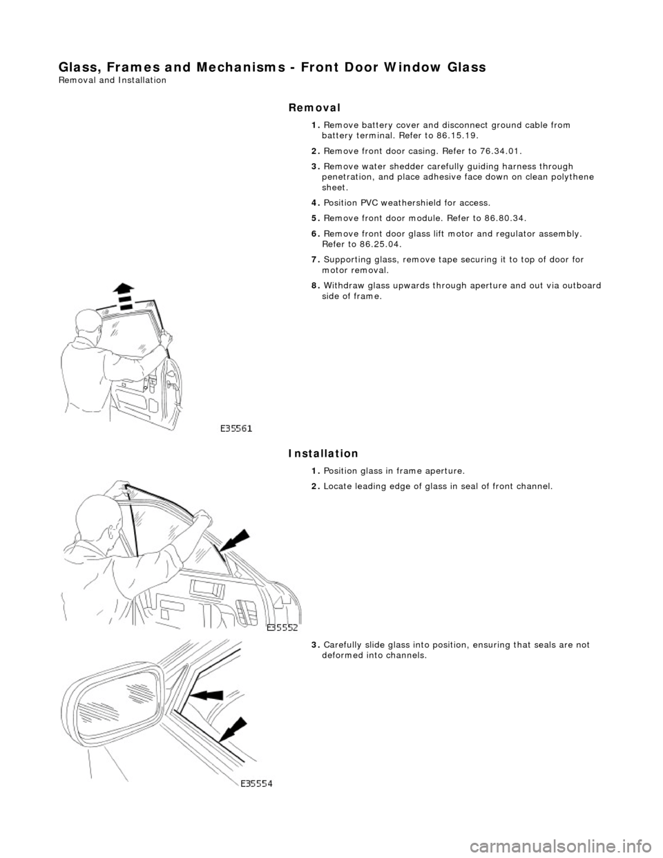
2. Remove front door casing. Refer to 76.34.01.
3. Remove water shedder carefu lly guiding harness through
penetration, and place adhesive face down on clean polythene
sheet.
4. Position PVC weathe rshield for access.
5. Remove front door modu le. Refer to 86.80.34.
6. Remove front door glass lift motor and regulator assembly.
Refer to 86.25.04.
7. Supporting glass, remove tape securing it to top of door for
motor removal.
8. Withdraw glass upwards through aperture and out via outboard side of frame.
1. Position glass in frame aperture.
2. Locate leading edge of glass in seal of front channel.
3. Carefully slide glass into position, ensuring that seals are not
deformed into channels.