lower JAGUAR X308 1998 2.G Workshop Manual
[x] Cancel search | Manufacturer: JAGUAR, Model Year: 1998, Model line: X308, Model: JAGUAR X308 1998 2.GPages: 2490, PDF Size: 69.81 MB
Page 1882 of 2490
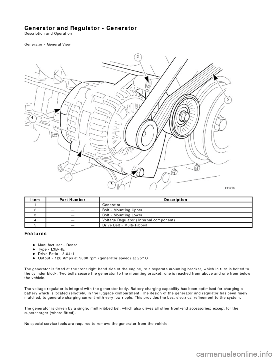
Generator and Regulator - Generator
Description and Operation
Generator - General View
Features
Manufacturer - Denso Type - L3B-HE Drive Ratio - 3.04:1 Output - 120 Amps at 5000 rpm (generator speed) at 25° C
The generator is fitted at the front right hand side of the engine, to a sepa rate mounting bracket, which in turn is bolted to
the cylinder block. Two bolts secure th e generator to the mounting bracket; one is reached from above and one from below
the vehicle.
The voltage regulator is integral with th e generator body. Battery charging capabi lity has been optimised for charging a
battery which is located remotely, in the luggage compartment. The design of the generator and regulator has been finely
matched, to generate charging current with very low ripple. This provides the best electrical refinement to the system.
The generator is driven by a single, multi-ribbed belt which also drives all other front-e nd accessories; except for the
supercharger (where fitted).
No special service tools are required to remove the generator from the vehicle.
ItemPart NumberDescription
1—Generator
2—Bolt - Mounting Upper
3—Bolt - Mounting Lower
4—Voltage Regulator (Internal component)
5—Drive Belt - Multi-Ribbed
Page 1890 of 2490
Generator and Regulator - Generator4.0L NA V8 - AJ27/3.2L NA V8 - AJ26
Removal and Installation
Removal
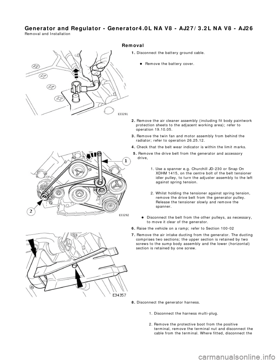
1. Disconnect the batt ery ground cable.
Remove the battery cover.
2. Remove the air cleaner assembly (including fit body paintwork
protection sheets to the adja cent working area); refer to
operation 19.10.05.
3. Remove the twin fan and moto r assembly from behind the
radiator; refer to operation 26.25.12.
4. Check that the belt wear indicator is within the limit marks.
5. Remove the drive belt from the generator and accessory
drive,
1. Use a spanner e.g. Churchill JD-230 or Snap On XDHM 1415, on the centre bo lt of the belt tensioner
idler pulley, to turn the adju ster assembly to the left
against spring tension.
2. Whilst holding the tensioner against spring tension, remove the drive belt from the generator pulley.
Release the tensioner sl owly and remove the
spanner.
Disconnect the belt from the ot her pulleys, as necessary,
to move it clear of the generator.
6. Raise the vehicle on a ramp; refer to Section 100-02
7. Remove the air intake ducting fr om the generator. The ducting
comprises two sections; the upper section is retained by two
screws to the sump body assembly and the lower (horizontal)
section is retained by one screw.
8. Disconnect the generator harness.
1. Disconnect the harness multi-plug.
2. Remove the protective boot from the positive
terminal, remove the termin al nut and disconnect the
cable from the terminal. Where fitted, disconnect the
Page 1891 of 2490

suppression module positive cable from the positive
terminal.
3. Where fitted, remove the nut which secures the
suppression module negati ve cable and disconnect
the cable from the generator. Reposition the
suppression module harness clear of the generator.
9. Remove the lower mounting bolt and reposition the harness
mounting bracket.
10. Remove the upper securing bolt and withdraw the generator
from the mounting bracket.
11. Carefully, manoeuvre the ge nerator forward towards the
radiator.
12. Change the position of the ge nerator and remove it upwards
between the engine and the radiator.
Page 1892 of 2490

Installation
13. Move the spacing bush rearward s slightly in the generator
mounting bracket, to ease fitting the new generator.
1. Position a suitable length bolt through the bush, fit a
tubular spacer or socket spanner, fit a nut and
tighten the assembly to move the bush slightly.
Remove the nut, bolt and spacer.
1. Fit the generator to the engine.
1. From above, position th e generator and fit the upper
mounting bolt and nut, but do not fully tighten.
2. Fit the generator lower mounting.
1. From below, reposition an d align the harness clip to
the generator lower mounting.
2. Fit the lower mounting bolt and nut, tighten to 38-48
Nm.
3. Connect the harness.
1. Reposition the suppres sion module harness and
connect the negative cable to the generator negative
terminal. Fit and tighten the terminal nut.
Page 1893 of 2490
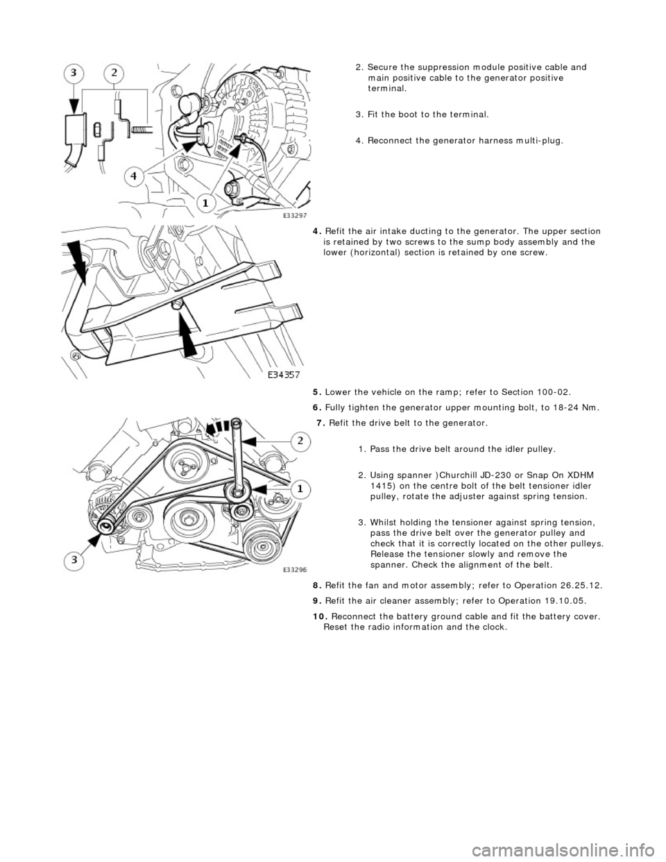
2. Secure the suppression module positive cable and
main positive cable to the generator positive
terminal.
3. Fit the boot to the terminal.
4. Reconnect the generator harness multi-plug.
4. Refit the air intake ducting to the generator. The upper section
is retained by two screws to the sump body assembly and the
lower (horizontal) section is retained by one screw.
5. Lower the vehicle on the ramp ; refer to Section 100-02.
6. Fully tighten the generator upper mounting bolt, to 18-24 Nm.
7. Refit the drive belt to the generator.
1. Pass the drive belt around the idler pulley.
2. Using spanner )Churchill JD-230 or Snap On XDHM 1415) on the centre bolt of the belt tensioner idler
pulley, rotate the adjuster against spring tension.
3. Whilst holding the tensioner against spring tension, pass the drive belt over the generator pulley and
check that it is correctly located on the other pulleys.
Release the tensioner slowly and remove the
spanner. Check the alignment of the belt.
8. Refit the fan and motor assembly ; refer to Operation 26.25.12.
9. Refit the air cleaner assembly; refer to Operation 19.10.05.
10. Reconnect the battery ground cable and fit the battery cover.
Reset the radio inform ation and the clock.
Page 1894 of 2490

Generator and Regulator - Generator4.0L SC V8 - AJ26
Removal and Installation
Removal
1. Disconnect the batt ery ground cable.
Remove the battery cover.
2. Remove the air cleaner assembly (including fit body paintwork
protection sheets to the adja cent working area); refer to
operation 19.10.05.
3. Remove the twin fan and moto r assembly from behind the
radiator; refer to operation 26.25.12.
4. Remove the supercharger drive belt; refer to operation
18.50.08.
5. Remove the supercharger driv e belt tensioner; refer to
operation 18.50.24.
6. Check that the belt wear indica tor (accessory drive) is within
the limit marks.
7. Remove the drive belt from the generator and accessory
drive,
1. Use a spanner e.g. Churchill JD-230 or Snap On XDHM 1415, on the centre bo lt of the belt tensioner
idler pulley, to turn the adju ster assembly to the left
against spring tension.
2. Whilst holding the tensioner against spring tension, remove the drive belt from the generator pulley.
Release the tensioner sl owly and remove the
spanner.
Disconnect the belt from the ot her pulleys, as necessary,
to move it clear of the generator.
8. Raise the vehicle on a ramp; refer to Section 100-02
9. Remove the air intake ducting fr om the generator. The ducting
comprises two sections; the upper section is retained by two
screws to the sump body assembly and the lower (horizontal)
section is retained by one screw.
10. Disconnect the generator harness.
Page 1895 of 2490
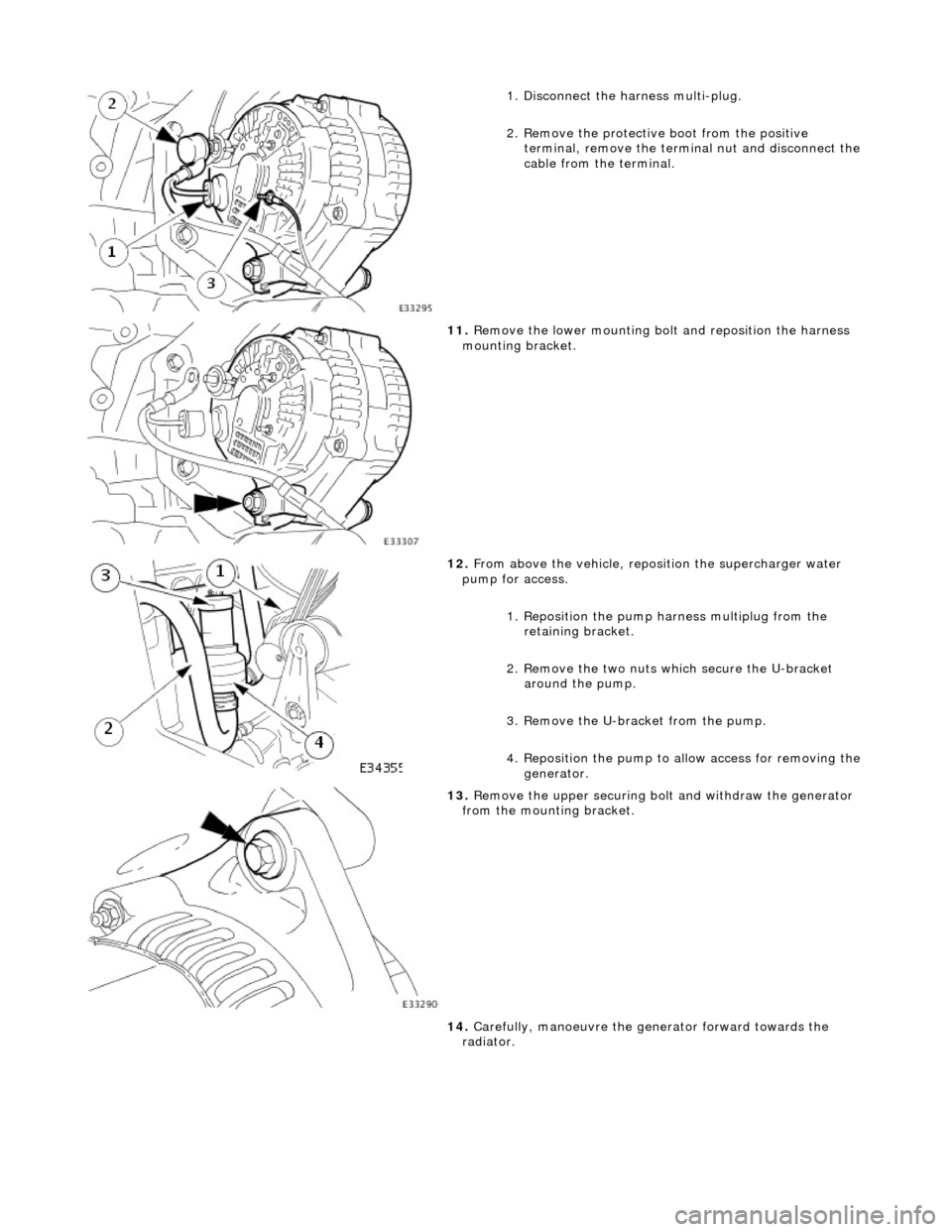
1. Disconnect the harness multi-plug.
2. Remove the protective boot from the positive
terminal, remove the termin al nut and disconnect the
cable from the terminal.
11. Remove the lower mounting bolt and reposition the harness
mounting bracket.
12. From above the vehicle, reposi tion the supercharger water
pump for access.
1. Reposition the pump harness multiplug from the
retaining bracket.
2. Remove the two nuts which secure the U-bracket around the pump.
3. Remove the U-bracket from the pump.
4. Reposition the pump to al low access for removing the
generator.
13. Remove the upper securing bolt and withdraw the generator
from the mounting bracket.
14. Carefully, manoeuvre the ge nerator forward towards the
radiator.
Page 1896 of 2490

Installation
15. Change the position of the ge nerator and remove it upwards
between the engine and the radiator.
16. Move the spacing bush rearward s slightly in the generator
mounting bracket, to ease fitting the new generator.
1. Position a suitable length bolt through the bush, fit a
tubular spacer or socket spanner, fit a nut and
tighten the assembly to move the bush slightly.
Remove the nut, bolt and spacer.
1. Fit the generator to the engine.
1. From above, position th e generator and fit the upper
mounting bolt and nut, but do not fully tighten.
2. Fit the generator lower mounting.
1. From below, reposition an d align the harness clip to
the generator lower mounting.
Page 1897 of 2490
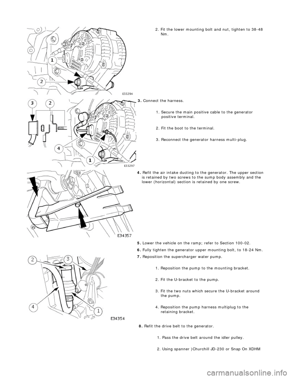
2. Fit the lower mounting bolt and nut, tighten to 38-48
Nm.
3. Connect the harness.
1. Secure the main positive cable to the generator positive terminal.
2. Fit the boot to the terminal.
3. Reconnect the generator harness multi-plug.
4. Refit the air intake ducting to the generator. The upper section
is retained by two screws to the sump body assembly and the
lower (horizontal) section is retained by one screw.
5. Lower the vehicle on the ramp ; refer to Section 100-02.
6. Fully tighten the generator upper mounting bolt, to 18-24 Nm.
7. Reposition the superc harger water pump.
1. Reposition the pump to the mounting bracket.
2. Fit the U-bracket to the pump.
3. Fit the two nuts which secure the U-bracket around the pump.
4. Reposition the pump harness multiplug to the retaining bracket.
8. Refit the drive belt to the generator.
1. Pass the drive belt around the idler pulley.
2. Using spanner )Churchill JD-230 or Snap On XDHM
Page 1909 of 2490
Antenna - Antenna
Diagnosis and Testing
Tests Using the Portable Diagnostic Unit
Refer to PDU User Guide
The PDU tests whether or not the antenna raises and lowers correctly. Although it is obvious if the antenna is not operating,
the PDU analyses why it is not operating an d indicates problems such as a faulty radio head signal output, faulty wiring, loss of power due to a blown fuse.