lower JAGUAR X308 1998 2.G Workshop Manual
[x] Cancel search | Manufacturer: JAGUAR, Model Year: 1998, Model line: X308, Model: JAGUAR X308 1998 2.GPages: 2490, PDF Size: 69.81 MB
Page 1798 of 2490

Air Conditioning - Air Conditioning
Description and Operation
Introduction
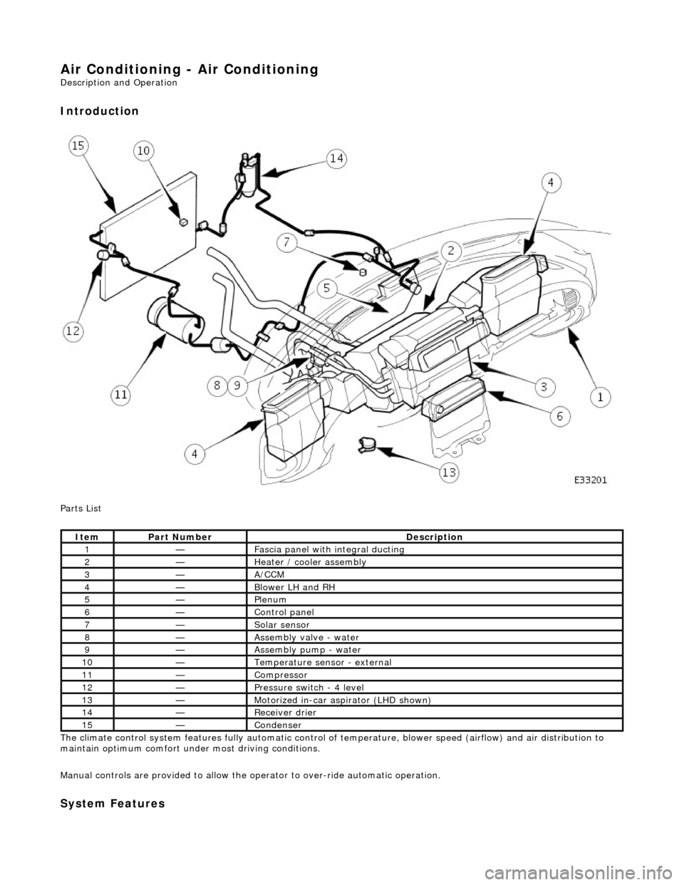
Parts List
The climate control system features fully automatic control of temperature, blower speed (airflow) and air distribution to
maintain optimum comfort under most driving conditions.
Manual controls are provided to allow the operator to over-ride automatic operation.
System Features
ItemPart NumberDescription
1—Fascia panel with integral ducting
2—Heater / cooler assembly
3—A/CCM
4—Blower LH and RH
5—Plenum
6—Control panel
7—Solar sensor
8—Assembly valve - water
9—Assembly pump - water
10—Temperature sensor - external
11—Compressor
12—Pressure switch - 4 level
13—Motorized in-car aspirator (LHD shown)
14—Receiver drier
15—Condenser
Page 1799 of 2490

Twin blower assemblies Center mounted evaporator, heater and air distribution unit Electric solenoid water valve controlled heating Electric water pump assembly Servo motor driven air distribution flaps Dedicated side glass defrost / demist vents External temperature sensor Motorised in-car aspirator Solar sensor
Electronic Control Panel
Liquid Crystal Display (LCD) Digital temperature display Manual fan speed level External temperature display Celsius / Fahrenheit selection Heated windshield switch (where fitted) Heated backlight switch Defrost switch Manual airflow distribution overrides (4) Access to self diagnostic system and error codes
Sensors
External ambient temperature sensor Motorized in-car aspirator Heater matrix temperature sensor Evaporator temperature sensor Solar sensor
These sensors feedback information to the Air Conditioning Control Module (A/CCM) which automatically adjusts air
temperature, airflow volume and distributi on from the air conditioning unit to maintain a stable passenger compartment
average temperature under changing weather conditions.
Major Components
Page 1802 of 2490

Parts List
The air conditioning unit houses the evap orator, heater matrix and their temperatur e sensors. The unit also incorporates
two servo motor operated air distribution flaps which regulate airflow to the front and rear footwells and the quantity of
airflow through the cool air bypass (air which by-passes he ater matrix) up to the upper air distribution box (ADB).
When the footwell flap is open, air is du cted to the front and rear footwell areas via the lower air distribution duct (LADD)
and appropriate ducts. The LADD is clipped to the bottom of the air conditioning unit case an d the front foot ducts clipped
onto the outlets of the LADD.
Condensate (water) which forms on the evaporator fins is drained out of the unit case through two drains, located either
side of the unit underneath the evaporator. The liquid is routed to the vehicle exterior via flexible tubes which are located
behind the firewa ll heatshield.
Refrigeration Cycle
ItemPart NumberDescription
1—Air inlet - LH (RH opposite, not shown)
2—Servomotor - cool air bypass
3—Servomotor - footwell outlet
4—Air outlet - footwell
5—Air outlet - ADB (with foam seal)
Page 1806 of 2490

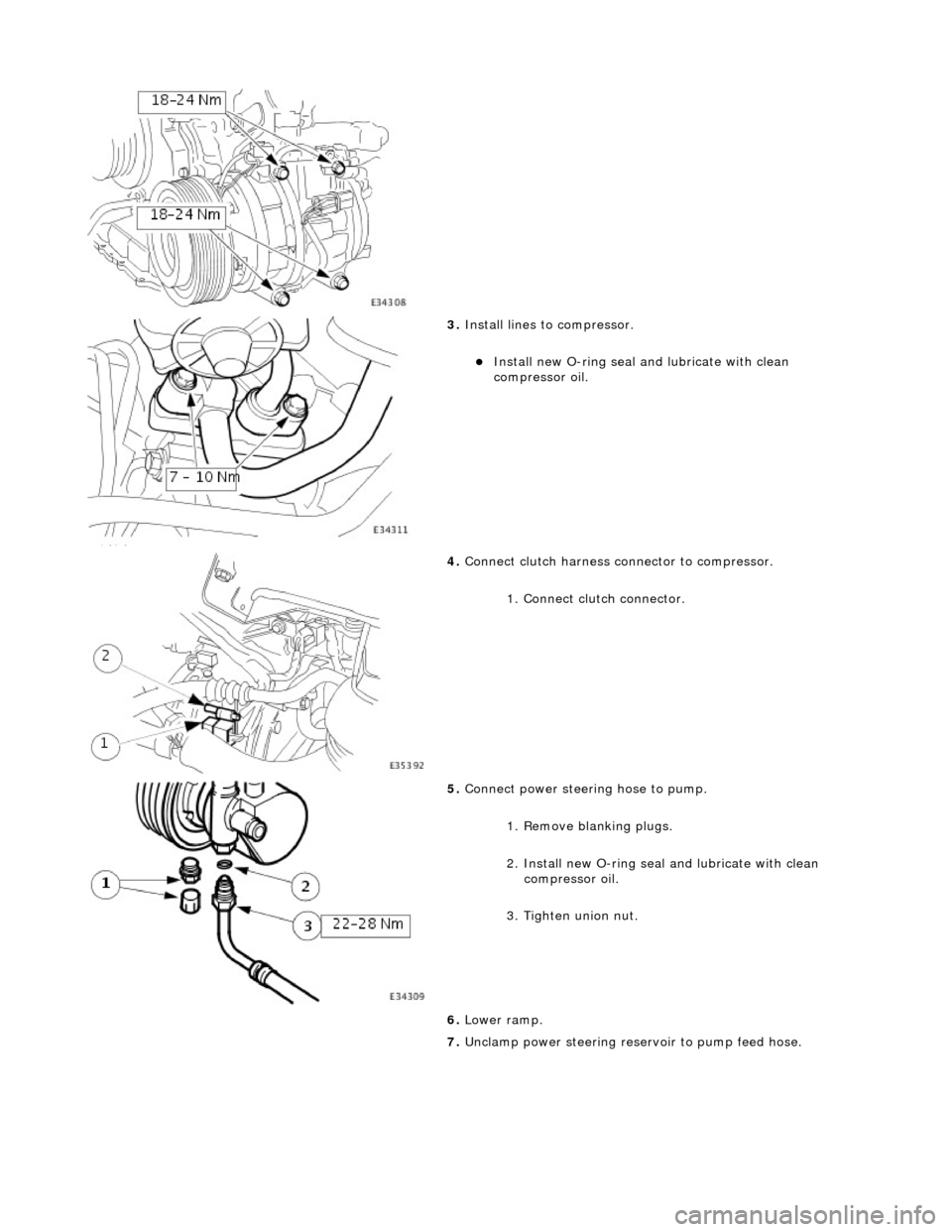
3. Install lines to compressor.
Install new O-ring seal and lubricate with clean
compressor oil.
4. Connect clutch harness connector to compressor.
1. Connect clutch connector.
5. Connect power steering hose to pump.
1. Remove blanking plugs.
2. Install new O-ring seal and lubricate with clean
compressor oil.
3. Tighten union nut.
6. Lower ramp.
7. Unclamp power steering rese rvoir to pump feed hose.
Page 1808 of 2490

Air Conditioning - Condenser Core
Removal and Installation
Removal
1. Disconnect battery ground cable (IMPORTANT, see SRO
86.15.19 for further information).
2. Drain radiator coolant only; refer to 26.10.01 or (SC)
26.10.01.
3. Recover refrigerant from air co nditioning system; refer to
82.30.30.
4. Release both gas struts, set the engine cover fully forward to
the service access position an d support with a wooden (or
similar) strut.
5. CAUTION: Take care not to damage hood or radiator
grille.
Remove twin fan and motor as sembly; refer to 26.25.12.
6. Disconnect radiator bleed hose.
Release connection.
7. Remove retaining clip which secures transmission oil cooler
upper and lower pipes.
8. Disconnect transmission oil cooler lower pipe from radiator.
1. Release union nut and disconne ct pipe.
Discard O-ring seal.
2. Install suitable blanking plugs.
9. From above the vehicle, discon nect transmission oil cooler
upper pipe from radiator.
1. Release union nut and disconne ct pipe.
Discard O-ring seal.
2. Install suitable blanking plugs.
Page 1811 of 2490

Installation
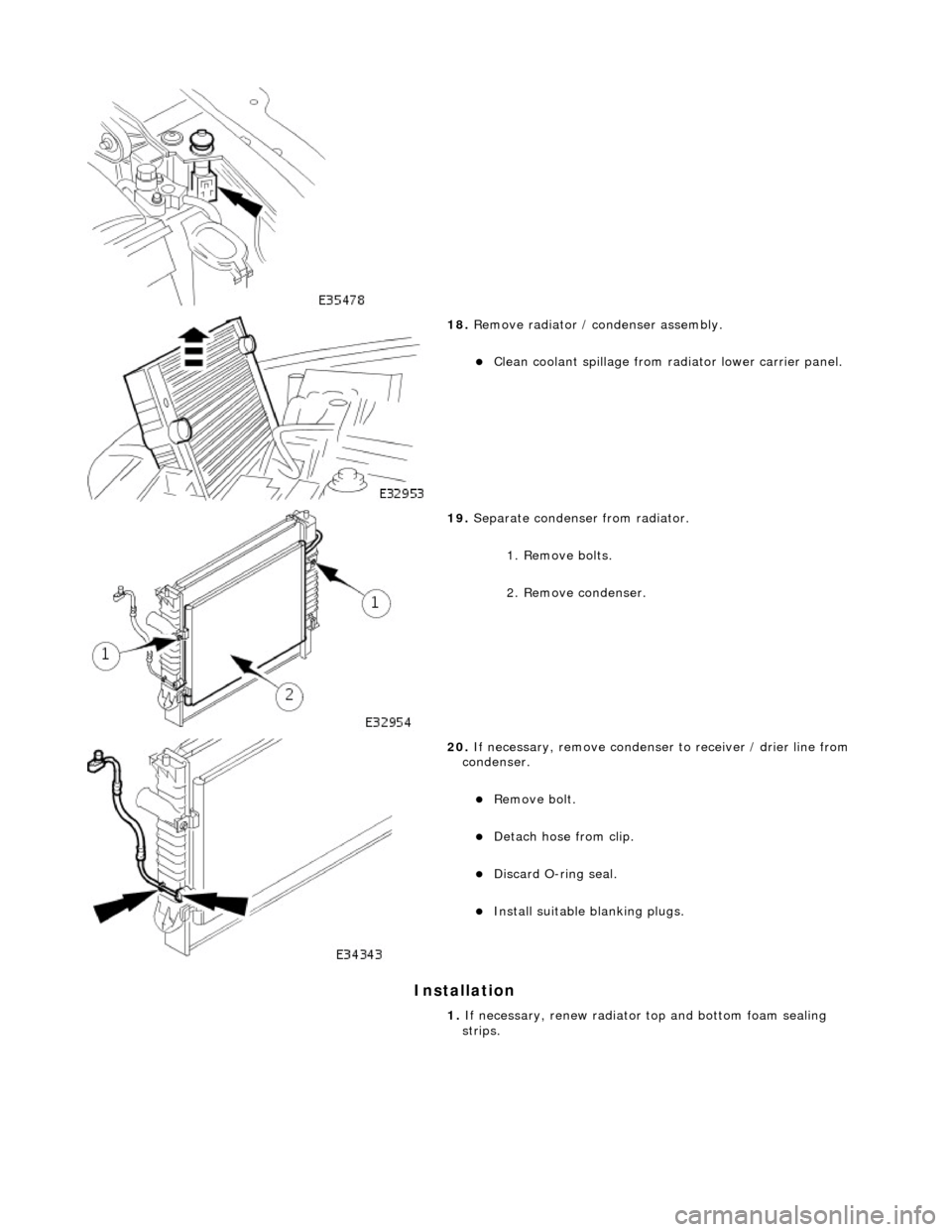
18. Remove radiator / condenser assembly.
Clean coolant spillage from radiator lower carrier panel.
19. Separate condenser from radiator.
1. Remove bolts.
2. Remove condenser.
20. If necessary, remove condenser to receiver / drier line from
condenser.
Remove bolt.
Detach hose from clip.
Discard O-ring seal.
Install suitable blanking plugs.
1. If necessary, renew radiator top and bottom foam sealing
strips.
Page 1813 of 2490

Connect hose.
Install bolt (8-10 Nm).
6. Connect compressor to condenser discharge line at condenser.
Remove blanking plugs.
Install new O-ring seal an d lubricate with clean A/C
compressor oil.
Connect hose.
Install bolt (8-10 Nm).
7. Connect transmission o il cooler upper pipe.
Remove blanking plugs.
Install new O-ring seal and lu bricate with clean automatic
transmission fluid.
Connect union nut to radiator and tighten.
8. Connect transmission oil cooler lower pipe.
Remove blanking plugs.
Install new O-ring seal and lu bricate with clean automatic
transmission fluid.
9. Connect radiator blee d hose to radiator.
Page 1816 of 2490

Air Conditioning - Evaporator Core
Removal and Installation
Removal
1. Remove heater / cooler unit; refer to 82.25.21.
2. Remove air conditioning control module from heater / cooler
unit.
Slacken upper fixing.
Remove lower fixings.
3. Remove evaporator pipe firewall seal plate.
Remove screws.
Remove plate.
4. Disconnect heater matrix temperature sensor.
Detach heater matrix temperature sensor connector from
unit.
Disconnect connector.
5. Remove footwell servo motor from heater / cooler unit.
Disconnect connector.
Remove screws.
Remove motor complete with bracket.
6. Disconnect evaporator sensor connector.
Page 1817 of 2490

Installation
Detach heater / cooler unit connector.
Detach evaporator sensor connector.
Disconnect connector.
7. Remove heater / cooler unit upper case from lower case.
Remove screw.
Remove 15 clips.
Remove upper case from lower case.
8. Remove evaporator from case.
Remove sensor and clip.
Remove evaporator.
1. Installation is the reverse of removal.
Page 1821 of 2490

Control Components - Control Components
Description and Operation
System Controls
The climate control system is controlled by : 1. 1. Manual input from the operator, via the center console located control panel.
2. 2. Automatically by means of the A/CCM.
Output is based upon input from the following devices:
Motorized In-car aspirator External air temperature sensor Coolant temperature sensor Heater 'air-off' (the temperature of the air leaving the matrix fins) temperature sensor Evaporator 'air-off' (the temperature of the air leaving the evaporator fins) temperature sensor Solar sensor Left hand blower recirculation / fresh air flap potentiometer Right hand blower recirculation / fresh air flap potentiometer Upper air distribution box (ADB) center and side face flap servomotor potentiometer ADB defrost flap servomotor potentiometer Air conditioning unit Foot flap servomotor potentiometer Air conditioning unit Cool Air Bypass flap servomotor potentiometer Thumbwheel controls on the facia vent assemblies which provide manu al adjustment of the airflow volume. Road and engine speed signals input to the A/CCM
Climate Control Panel
Communication between the control panel and the A/CCM is via a serial data communications link.
Switching the Climate Control system ON
The climate control system can be switched ON by pressing one of the following :
Ref #1 On / Off (resumes the system on in the previous settings).
Ref #10 A / C (resumes the system on in the previous settings).
Ref #11 AUTO (resumes the system on at the previous temperature setting).