accessory drive JAGUAR X308 1998 2.G Owner's Guide
[x] Cancel search | Manufacturer: JAGUAR, Model Year: 1998, Model line: X308, Model: JAGUAR X308 1998 2.GPages: 2490, PDF Size: 69.81 MB
Page 1058 of 2490

Accessory Drive - Accessory
Drive Belt Tensioner4.0L SC V8 - AJ26
Re
mo
val and Installation
I
n
stallation
1.
Op
en the engine compartment and fit paintwork protection
sheets.
2. Remove the supercharger driv e belt, for access. Refer to
operation 18.50.08.
3. Remove the accessory drive belt for access. Refer to Operation
(12.10.40)
4. Remove t
he tensioner assembly, which includes the tensioner
pulley..
1. Remove the bolt whic h secures the tensioner
assembly to the engine.
2. Remove the tensioner assembly.
1. Installation is the reverse of the removal procedure. Tighten
the tensioner assembly securing bolt to 38-48 Nm. Ensure that
the belt is correctly and squa rely located on each pulley.
2. Refit the supercharger drive belt. Refer to operation 18.50.08.
Page 1061 of 2490

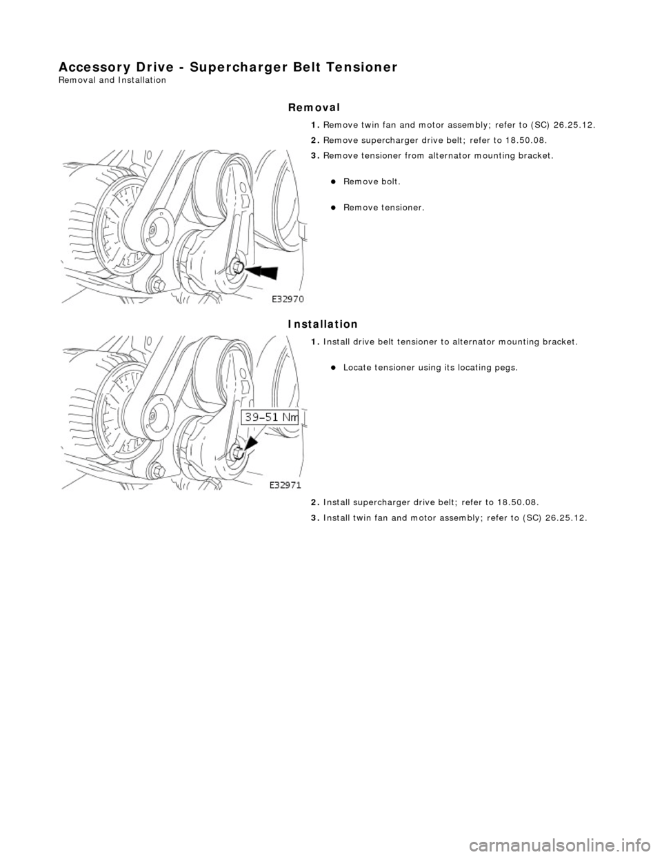
Accessory Drive - Supercharger B
elt Tensioner
Re
moval and Installation
Remov
al
Installation
1.
R
emove twin fan and motor asse
mbly; refer to (SC) 26.25.12.
2. Remove supercharger drive belt; refer to 18.50.08.
3. R
emove tensioner from altern
ator mounting bracket.
Re
move bolt.
R
emove tensioner.
1. Inst
all drive belt tensioner to
alternator mounting bracket.
Locat
e tensioner using its locating pegs.
2. Install supercharger driv e belt; refer to 18.50.08.
3. Install twin fan and motor asse mbly; refer to (SC) 26.25.12.
Page 1201 of 2490

leak
/blockage
EVAP valve failure
P0444Evaporati
ve emissions system
(EVAP) valve circuit open circuit
EVAP t
o ECM drive circuit open
circuit or high resistance
EVAP failu
re
F
or evaporative emissions pinpoint
tests,
REFER to Section 303
-1
3 Evaporative
Emiss
ions
.
P0445Evaporati
ve emissions system
(EVAP) valve circuit short circuit
E
VAP to ECM drive circuit short
circuit to ground
EVAP failu
re
F
or evaporative emissions pinpoint
tests,
REFER to Section 303
-1
3 Evaporative
Emiss
ions
.
P0447Cani
ster close valve (CCV) circuit
open circuit
CCV to ECM
drive circuit open
circuit, high resi stance or short
circuit to ground
EVAP failu
re
F
or evaporative emissions pinpoint
tests,
REFER to Section 303
-1
3 Evaporative
Emiss
ions
.
P0448Cani
ster close valve (CCV) circuit
short circuit
CCV to
ECM drive circuit short
circuit to high voltage
CCV failure
F
or evaporative emissions pinpoint
tests,
REFER to Section 303
-1
3 Evaporative
Emiss
ions
.
P0452F
uel tank pressure (FTP) sensor
circuit low voltage
FTP
sensor disconnected
FTP
sensor to ECM sense circuit
open circuit or short circuit to
ground
FTP sen
sor to ECM power supply
circuit open circuit or short circuit
to ground
F
TP sensor failure
F
or evaporative emissions pinpoint
tests,
REFER to Section 303
-1
3 Evaporative
Emiss
ions
.
P0453F
uel tank pressure (FTP) sensor
circuit high voltage
FTP
sensor to ECM signal ground
circuit open circuit
F
TP sensor to ECM wiring (supply,
sense, signal, ground) short circuit
to each other
FTP
sensor to ECM sense circuit
short circuit to high voltage
F
TP sensor failure
F
or evaporative emissions pinpoint
tests,
REFER to Section 303
-1
3 Evaporative
Emiss
ions
.
P0460Fue
l level sense signal
performance
Fue
l level sensor
to instrument
cluster circuits in termittent short or
open circuit
F
uel level sensor failure
Instrument cluster
faul
t (incorrect
fuel level data)
F
or fuel level sensor
circuit tests,
REFER to Section 303
-04
Fuel
Charging and Con
trols
.
P0506Idl
e rpm lower than expected
Ai
r intake blockage
Acce
ssory drive overload
(defective/siezed component)
Thr
ottle valve stuck closed
Throttl
e assembly failure
Chec
k the air intake system.
REFER to Section 303
-1
2 Intake Air
Distribu
tion and Filtering
.
Check t
he accessory drive
components,
REFER to Section 303
-0
5 Accessory
Dr
ive
.
F
or throttle body information,
REFER to Section 303
-04
Fuel
Charging and Con
trols
.
P0507Idle rpm
higher than expected
Inta
ke air leak between MAF
sensor and throttle
Inta
ke air leak between throttle
and engine
Engine
breather leak
Cruis
e (speed) control vacuum
failure
Thr
ottle valve stuck open
Throttl
e assembly failure
Chec
k the air intake system.
REFER to Section 303
-1
2 Intake Air
Distribu
tion and Filtering
.
Chec
k the engine breather system,
REFER to Section 303
-08
Engine
Emissi
on Control
.
F
or cruise (speed) control information,
REFER to Section 310
-03
Speed
Control.
F
or throttle body information,
REFER to Section 303
-04
Fuel
Charging and Con
trols
.
P0560Vehicle voltage
malfunction
ECM battery
power supply open
circuit, high resistance
F
or ECM power supply circuit tests,
GO to Pinpoint Test AD.
.
P0566Cruise (speed) contr
ol
CANCEL
switch ON fault
Cru
ise (speed) control switches
internal steering wheel short circuit
to ground
For cru
ise (speed) control circuit tests,
REFER to Section 310
-03
Speed
Page 1800 of 2490

Compressor:
Features
Engine mounted, driven by the accessory drive belt. Fixed displacement type. High-pressure relief valve, to avoid system over-pressure. ECM controlled clutch energized via a relay.
Receiver drier:
Vertically mounted on the ri ght-hand side of the engine compartment next to the engine coolant radiator. Fitted with the high-side charge port. Includes a fluorescent tracer dye me chanism to aid leak detection.
ItemPart NumberDescription
1—Compressor assembly
2—Condenser
3—Evaporator and heater matrix (internal)
4—Receiver drier
5—4-level pressure switch
6—Expansion valve (internal)
7—High-side charge port
8—Low-side charge port
9—Suction muffler
10—Discharge hose
11—Discharge pipe
12—Suction hose
13—Suction pipe
14—Liquid line
15—Jumper hose (condenser hose)
Page 1804 of 2490

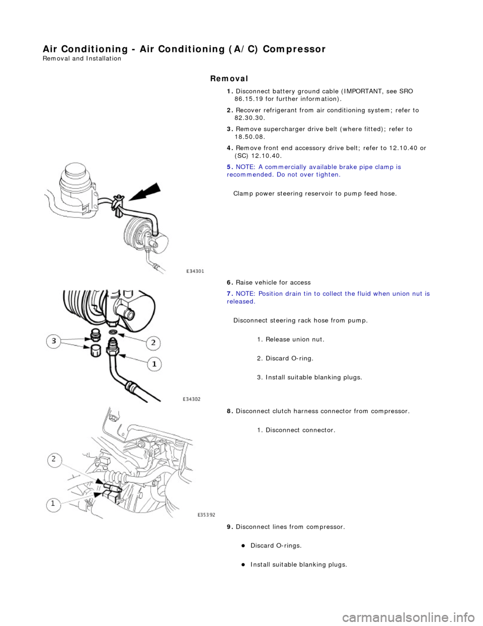
Air Conditioning - Air Conditioning (A/C) Compressor
Removal and Installation
Removal
1. Disconnect battery ground cable (IMPORTANT, see SRO
86.15.19 for further information).
2. Recover refrigerant from air co nditioning system; refer to
82.30.30.
3. Remove supercharger drive belt (where fitted); refer to
18.50.08.
4. Remove front end accessory dr ive belt; refer to 12.10.40 or
(SC) 12.10.40.
5. NOTE: A commercially availa ble brake pipe clamp is
recommended. Do not over tighten.
Clamp power steering reservoir to pump feed hose.
6. Raise vehicle for access
7. NOTE: Position drain tin to collect the fluid when union nut is
released.
Disconnect steering rack hose from pump. 1. Release union nut.
2. Discard O-ring.
3. Install suitable blanking plugs.
8. Disconnect clutch harness connector from compressor.
1. Disconnect connector.
9. Disconnect lines from compressor.
Discard O-rings.
Install suitable blanking plugs.
Page 1807 of 2490

8. Install front end accessory drive belt; refer to 12.10.40 or (SC)
12.10.40.
9. Install supercharger drive belt (where fitted); refer to
18.50.08.
10. Reconnect battery ground cable (IMPORTANT, see SRO
86.15.15 for further information).
11. Recharge air conditioning system; refer to 82.30.30.
12. Check / bleed / top up power stee ring fluid reservoir; refer to
211-02.
Page 1890 of 2490

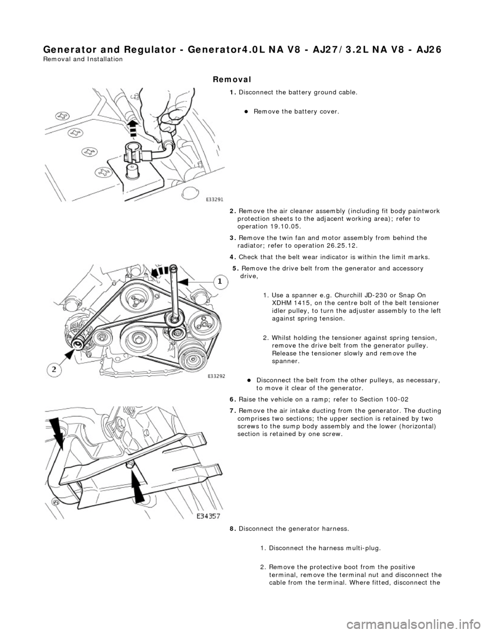
Generator and Regulator - Generator4.0L NA V8 - AJ27/3.2L NA V8 - AJ26
Removal and Installation
Removal
1. Disconnect the batt ery ground cable.
Remove the battery cover.
2. Remove the air cleaner assembly (including fit body paintwork
protection sheets to the adja cent working area); refer to
operation 19.10.05.
3. Remove the twin fan and moto r assembly from behind the
radiator; refer to operation 26.25.12.
4. Check that the belt wear indicator is within the limit marks.
5. Remove the drive belt from the generator and accessory
drive,
1. Use a spanner e.g. Churchill JD-230 or Snap On XDHM 1415, on the centre bo lt of the belt tensioner
idler pulley, to turn the adju ster assembly to the left
against spring tension.
2. Whilst holding the tensioner against spring tension, remove the drive belt from the generator pulley.
Release the tensioner sl owly and remove the
spanner.
Disconnect the belt from the ot her pulleys, as necessary,
to move it clear of the generator.
6. Raise the vehicle on a ramp; refer to Section 100-02
7. Remove the air intake ducting fr om the generator. The ducting
comprises two sections; the upper section is retained by two
screws to the sump body assembly and the lower (horizontal)
section is retained by one screw.
8. Disconnect the generator harness.
1. Disconnect the harness multi-plug.
2. Remove the protective boot from the positive
terminal, remove the termin al nut and disconnect the
cable from the terminal. Where fitted, disconnect the
Page 1894 of 2490

Generator and Regulator - Generator4.0L SC V8 - AJ26
Removal and Installation
Removal
1. Disconnect the batt ery ground cable.
Remove the battery cover.
2. Remove the air cleaner assembly (including fit body paintwork
protection sheets to the adja cent working area); refer to
operation 19.10.05.
3. Remove the twin fan and moto r assembly from behind the
radiator; refer to operation 26.25.12.
4. Remove the supercharger drive belt; refer to operation
18.50.08.
5. Remove the supercharger driv e belt tensioner; refer to
operation 18.50.24.
6. Check that the belt wear indica tor (accessory drive) is within
the limit marks.
7. Remove the drive belt from the generator and accessory
drive,
1. Use a spanner e.g. Churchill JD-230 or Snap On XDHM 1415, on the centre bo lt of the belt tensioner
idler pulley, to turn the adju ster assembly to the left
against spring tension.
2. Whilst holding the tensioner against spring tension, remove the drive belt from the generator pulley.
Release the tensioner sl owly and remove the
spanner.
Disconnect the belt from the ot her pulleys, as necessary,
to move it clear of the generator.
8. Raise the vehicle on a ramp; refer to Section 100-02
9. Remove the air intake ducting fr om the generator. The ducting
comprises two sections; the upper section is retained by two
screws to the sump body assembly and the lower (horizontal)
section is retained by one screw.
10. Disconnect the generator harness.
Page 1977 of 2490

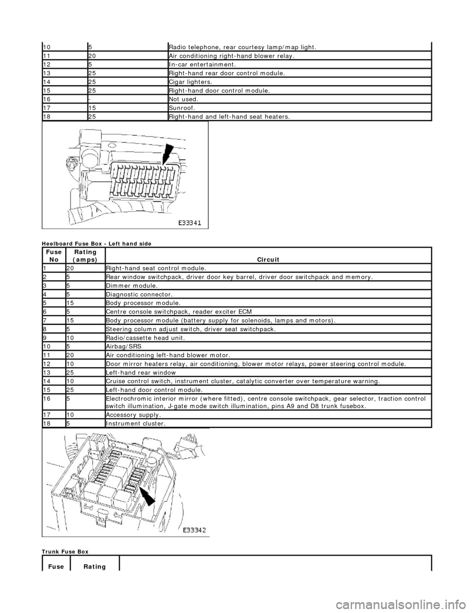
Heelboard Fuse Box - Left hand side
Trunk Fuse Box
105Radio telephone, rear courtesy lamp/map light.
1120Air conditioning right-hand blower relay.
125In-car entertainment.
1325Right-hand rear door control module.
1425Cigar lighters.
1525Right-hand door control module.
16-Not used.
1715Sunroof.
1825Right-hand and left-hand seat heaters.
Fuse NoRating
(amps)Circuit
120Right-hand seat control module.
25Rear window switchpack, driver door key ba rrel, driver door switchpack and memory.
35Dimmer module.
45Diagnostic connector.
515Body processor module.
65Centre console switchpack, reader exciter ECM
715Body processor module (battery supply for solenoids, lamps and motors).
85Steering column adjust switch, driver seat switchpack.
910Radio/cassette head unit.
105Airbag/SRS
1120Air conditioning left-hand blower motor.
1210Door mirror heaters relay, air conditioning, blow er motor relays, power steering control module.
1325Left-hand rear window
1410Cruise control switch, instrument cluster, catalytic converter over temperature warning.
1525Left-hand door control module.
165Electrochromic interior mirror (where fitted), centre console switchpack, gear selector, traction control
switch illumination, J-gate mode switch illumination, pins A9 and D8 trunk fusebox.
1710Accessory supply.
185Instrument cluster.
Fuse Rating