body JAGUAR X308 1998 2.G Repair Manual
[x] Cancel search | Manufacturer: JAGUAR, Model Year: 1998, Model line: X308, Model: JAGUAR X308 1998 2.GPages: 2490, PDF Size: 69.81 MB
Page 464 of 2490
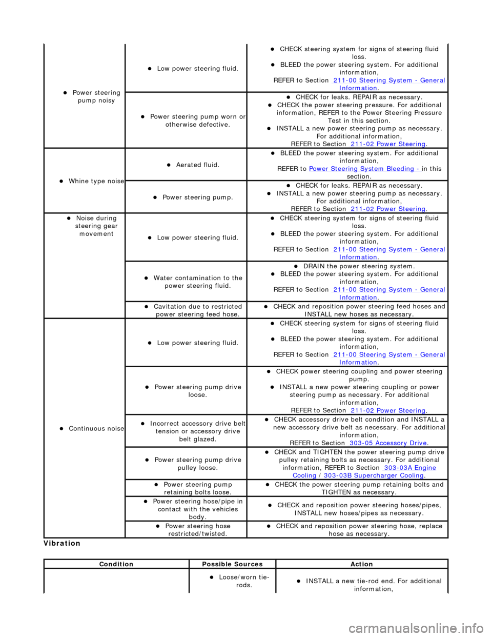
Vibrati
on
Power steeri
ng
pump noisy
Low power steer i
ng fluid.
CHECK
steering system for s
igns of steering fluid
loss.
BLEE D the
power steering system. For additional
information,
REFER to Section 211
-0 0
Steering System
-
Ge n
eral
Informati
o
n
.
Power steeri
ng pump wor
n or
otherwise defective.
CHECK for leaks. R
EPAIR as necessary.
CHECK
the power steering pressure. For additional
information, REFER to th e Power Steering Pressure
Test in this section.
INST ALL a ne
w power steering pump as necessary.
For additional information,
REFER to Section 211
-0 2
Power Steering
.
Wh
in
e type noise
Aerated flui
d.
BLEE
D the
power steering system. For additional
information,
REFER to Power Steering System Bleeding
- in t h
is
section.
Power steering pump.
CHECK for leaks. R
EPAIR as necessary.
INSTALL a ne
w power steering pump as necessary.
For additional information,
REFER to Section 211
-0 2
Power Steering
.
No
i
se during
steering gear movement
Low power steer i
ng fluid.
CHECK
steering system for s
igns of steering fluid
loss.
BLEE D the
power steering system. For additional
information,
REFER to Section 211
-0 0
Steering System
-
Ge n
eral
Informati
o
n
.
Water co
n
tamination to the
power steering fluid.
DR AIN
the power steering system.
BLEE
D the
power steering system. For additional
information,
REFER to Section 211
-00
Steering System
-
Gen
eral
Informati
o
n
.
Cavi
tation due to restricted
po
wer steering feed hose.
CHECK
and reposition power
steering feed hoses and
INSTALL new hoses as necessary.
Continu o
us noise
Low power steer i
ng fluid.
CHECK
steering system for s
igns of steering fluid
loss.
BLEE D the
power steering system. For additional
information,
REFER to Section 211
-0 0
Steering System
-
Ge n
eral
Informati
o
n
.
Power steeri
ng pump dri
ve
loose.
CHECK
power steering coupli
ng and power steering
pump.
IN ST
ALL a new power steering coupling or power
steering pump as nece ssary. For additional
information,
REFER to Section 211
-0 2
Power Steering
.
Incorre
ct
accessory drive belt
tension or accessory drive belt glazed.
CHECK acc
essory drive belt condition and INSTALL a
new accessory drive belt as necessary. For additional
information,
REFER to Section 303
-0 5 Ac
cessory Drive
.
Power steeri
ng pump dri
ve
pulley loose.
CHECK
and TIGHTEN the power steering pump drive
pulley retaining bolts as necessary. For additional
information, REFER to Section 303
-03A En
gine
Coo
ling / 30 3-03
B Supercharger Cooling
.
Power steeri
ng pump
r
etaining bolts loose.
CHECK
the power steering pump retaining bolts and
TIGHTEN as necessary.
Power steering hose/pipe in c
ontact with the vehicles
body.
CHECK
and reposition powe
r steering hoses/pipes,
INSTALL new hoses/pipes as necessary.
Power steeri ng hose
r
estricted/twisted.
CHECK
and reposition powe
r steering hose, replace
hose as necessary.
Conditi
on
Possibl
e Sources
Actio
n
Loose/worn tie-
ro
ds.
INST
ALL a new tie-r
od end. For additional
information,
Page 468 of 2490
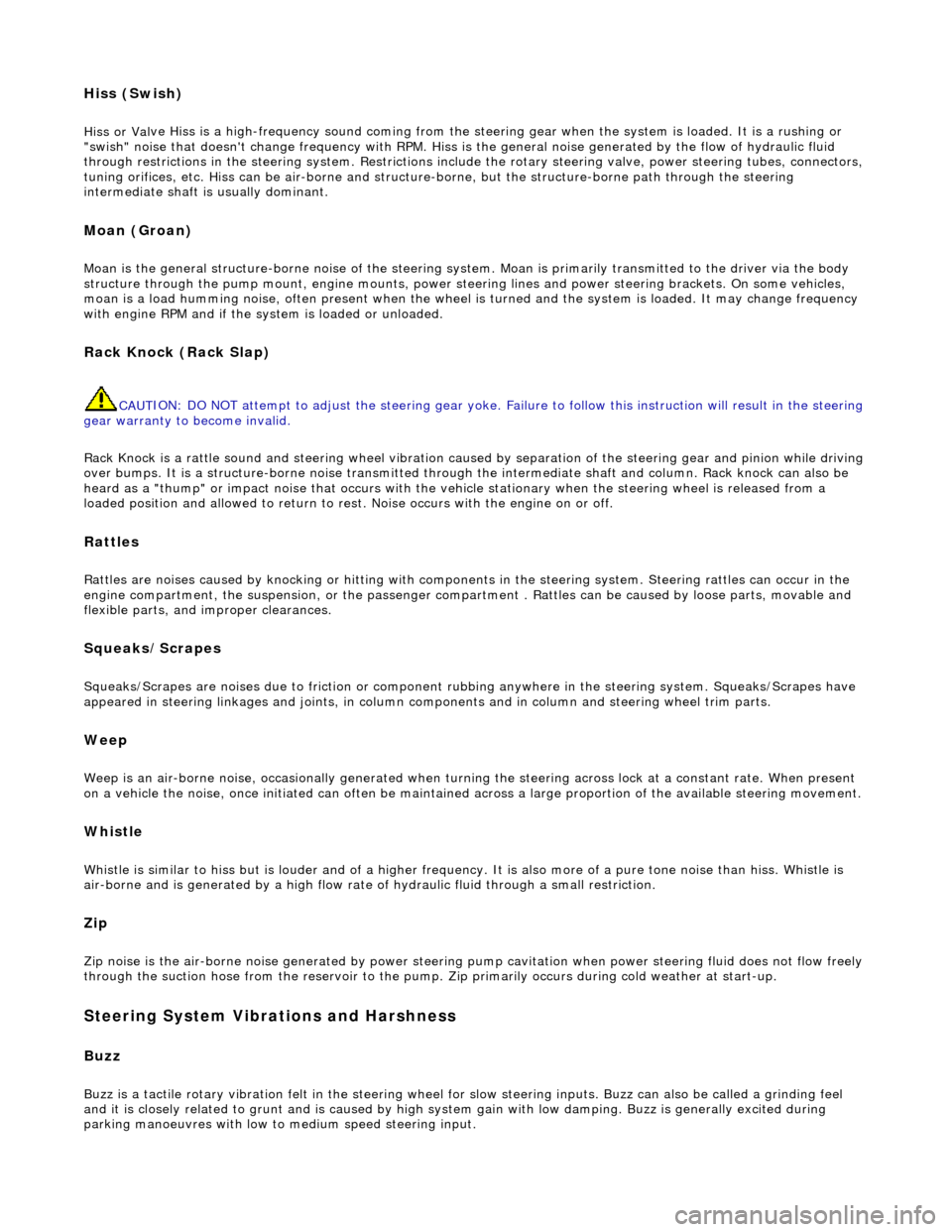
Hiss (Swish)
Hiss or Val
ve Hiss is a high-frequency so
und coming from the steering gear when the system is loaded. It is a rushing or
"swish" noise that doesn't change frequency with RPM. Hiss is the general noise generated by the flow of hydraulic fluid
through restrictions in the steer ing system. Restrictions include the rotary stee ring valve, power steering tubes, connectors,
tuning orifices, etc. Hiss can be air- borne and structure-borne, but the structure-borne path through the steering
intermediate shaft is usually dominant.
Moan (Groan)
Moan is the general structu r
e-borne noise of the steering system. Moan is primarily transmitted to the driver via the body
structure through the pump mount, engine mounts, power steering lines and power steering brackets. On some vehicles,
moan is a load humming noise, often present when the wheel is turned and the system is loaded. It may change frequency
with engine RPM and if the sy stem is loaded or unloaded.
Rack Knock (R
ack Slap)
CAU
T
ION: DO NOT attempt to adjust the stee
ring gear yoke. Failure to follow this instruction will result in the steering
gear warranty to become invalid.
Rack Knock is a rattle sound an d steering wheel vibration caused by separation of the steering gear and pinion while driving
over bumps. It is a structure-borne noise transmitted throug h the intermediate shaft and column. Rack knock can also be
heard as a "thump" or impact noise that occurs with the vehicle stationary when the steering wheel is released from a
loaded position and allowed to return to rest . Noise occurs with the engine on or off.
Rattles
Ra
ttles are noises caused by knocking or hitting with components in the steering system. Steering rattles can occur in the
engine compartment, the suspension, or the passenger compartment . Rattles can be caused by loose parts, movable and
flexible parts, and improper clearances.
Squea k
s/Scrapes
Squeaks/Scrapes are noises due
to fri
ction or component rubbi
ng anywhere in the steering system. Squeaks/Scrapes have
appeared in steering linkages and jo ints, in column components and in co lumn and steering wheel trim parts.
Weep
We
ep is an air-borne noise, occasionally
generated when turning the steering across lock at a constant rate. When present
on a vehicle the noise, once initiated can often be maintained across a large proportion of the available steering movement.
Whistle
Wh
istle is similar to hiss but is louder and of a higher frequency. It is also more
of a pure tone noise than hiss. Whistle is
air-borne and is generated by a high flow rate of hydraulic fluid through a small restriction.
Zip
Zip n
o
ise is the air-borne noise
generated by power steerin g pump cavitation when power steering fluid does not flow freely
through the suction hose from the rese rvoir to the pump. Zip primarily occurs during cold weather at start-up.
Steering System Vibrations and Harshne
ss
Buzz
Buzz is a tactile rotary vi
bration felt in
the steering wheel for slow steering inputs. Buzz can also be called a grinding feel
and it is closely related to grunt and is caused by high system gain with low damping. Buzz is generally excited during
parking manoeuvres with low to medium speed steering input.
Page 478 of 2490
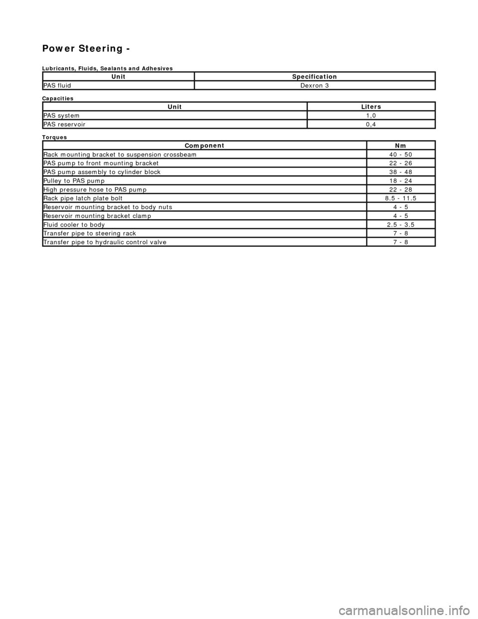
Power Steering -
Lubric
ants, Fluids, Sealants and Adhesives
Capacities
Torques
UnitSp
ecification
PAS flu
i
d
De
xr
on 3
UnitLi
t
ers
PAS syste
m1,0
PAS reservoi
r0,4
Com p
onent
Nm
Rac
k
mountin
g brac
ke
t to suspension crossbeam
40
- 50
PAS pump to front mounti
ng bracket
22
-
26
P
AS pu
mp assembly to cylinder block
38
-
48
Pul
l
ey to PAS pump
18
-
24
Hi
gh pressure hose to PAS pump22 -
28
Rack
pipe latch plate bolt8.5 -
11.5
R
e
servoir mounting bracket to body nuts
4 -
5
R
e
servoir mounting bracket clamp
4 -
5
Fluid cooler to body2.
5 -
3.5
Transfer pipe
to steering rack7 -
8
Transfer pipe
to hydraulic con
trol valve
7 -
8
Page 485 of 2490
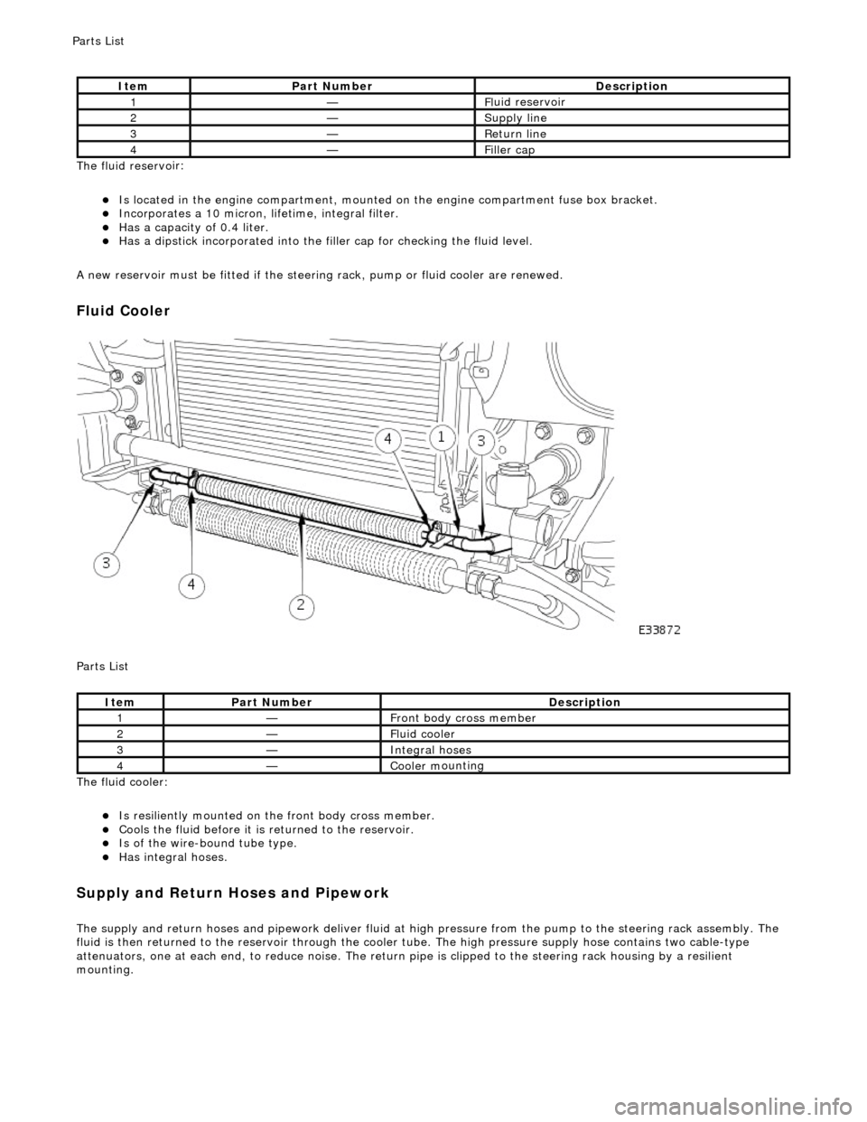
The fluid reservo
ir:
Is lo
cated in the engine compartment, mounted on the engine compartment fuse box bracket.
Incorporates
a 10 micron, li
fetime, integral filter.
Has a cap
acity of 0.4 liter.
Has a dipsti
ck incorporated into the filler cap for checking the fluid level.
A new reservoir must be fitted if the steering rack, pump or fluid cooler are renewed.
Fluid C
ooler
P
arts List
The fluid cooler:
Is
resiliently mounted on th
e front body cross member.
Coo
ls the fluid before it is
returned to the reservoir.
Is
of the wire-bound tube type.
Has i
ntegral hoses.
Supply and Return Hoses a
nd Pipework
The supply and return h
oses and
pipework deliver fluid at high pressure from the pump to th e steering rack assembly. The
fluid is then returned to th e reservoir through the cooler tube. The high pressure supply hose contains two cable-type
attenuators, one at each end, to reduce nois e. The return pipe is clipped to the steering rack housing by a resilient
mounting.
It
em
Par
t Number
De
scription
1—Fl
uid reservoir
2—Supply line
3—R
eturn line
4—Fi
ller cap
It
em
Par
t Number
De
scription
1—Front body cross member
2—F
luid cooler
3—Inte
gral hoses
4—Cooler m
ounting
P
arts List
Page 504 of 2490
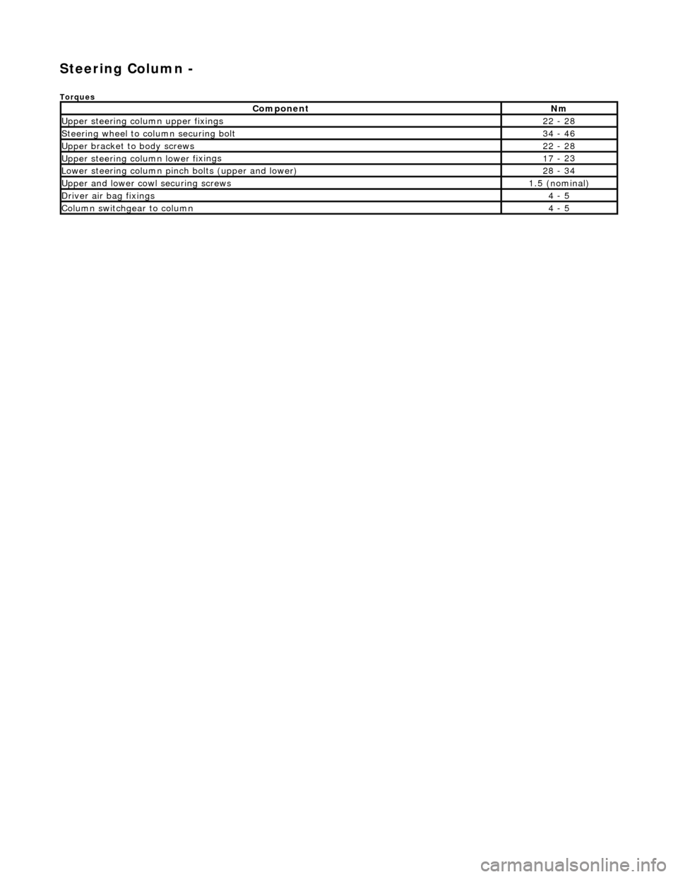
Steering Column -
Torques
Comp
onent
Nm
Upper
steering column upp
er fixings
22
-
28
S
t
eering wheel to column securing bolt
34
-
46
Upper
bracket
to body screws
22
-
28
Upper
steering colu mn lower fi
xings
17
-
23
Lower steeri
ng col
umn pinch bolts (upper and lower)
28
-
34
U
pper
and lower cowl securing screws
1.
5 (
nominal)
D
river ai
r bag fixings
4 -
5
Colum
n switchgear to column
4 -
5
Page 528 of 2490
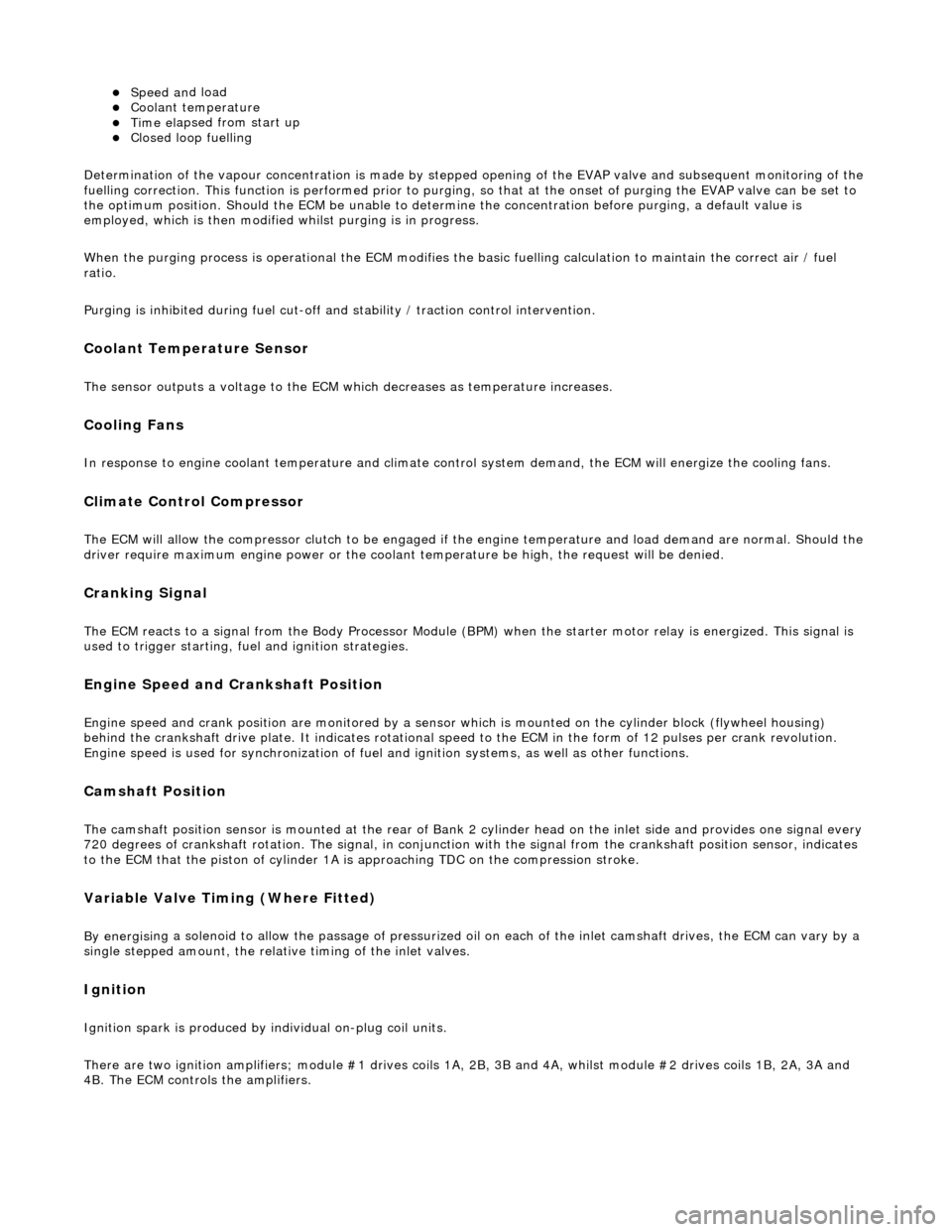
Speed an
d load
Coo
l
ant temperature
Ti
me el
apsed from start up
Cl
osed l
oop fuelling
Determination of the vapour concentration is made by stepped opening of the EVAP valve and subsequent monitoring of the
fuelling correction. This function is performed prior to purging, so that at the onse t of purging the EVAP valve can be set to
the optimum position. Should the ECM be unable to determine the concentration before purging, a default value is
employed, which is then modified whilst purging is in progress.
When the purging process is operational th e ECM modifies the basic fuelling calculation to maintain the correct air / fuel
ratio.
Purging is inhibited during fuel cut-off and stability / traction control intervention.
Coolant Temperature Sen
sor
Th
e
sensor outputs a voltage to the ECM which decreases as temperature increases.
Cooling Fans
In response to engi
ne coolant temperat
u
re and climate control system demand, the ECM will energize the cooling fans.
Climate Control Compressor
The E
C
M will allow the compressor clutch to be engaged if th
e engine temperature and load demand are normal. Should the
driver require maximum engine powe r or the coolant temperature be high, the request will be denied.
Cranking Signal
The ECM reacts to a signal fr
om th
e Body Processor Module (BPM) when the starter motor relay is energi
zed. This signal is
used to trigger starting, fu el and ignition strategies.
Engine Speed and Cranksh
aft Position
Engine
speed and cran
k position are moni
tored by a sensor which is mounted on the cylinder block (flywheel housing)
behind the crankshaft drive plat e. It indicates rotational speed to the ECM in the form of 12 pulses per crank revolution.
Engine speed is used for synchronization of fuel an d ignition systems, as well as other functions.
Camshaft Position
The ca
mshaft position sensor is mounted at
the rear of Bank 2 cylinder head on the inlet side and provides one signal every
720 degrees of crankshaft rotation. The signal, in conjunction with the signal from the crankshaft position sensor, indicates
to the ECM that the piston of cylinder 1A is approaching TDC on the compression stroke.
Variable Valve
Timing (Where Fitted)
By energi
si
ng a solenoid to allow the pass
age of pressurized oil on each of the inle t camshaft drives, the ECM can vary by a
single stepped amount, the relati ve timing of the inlet valves.
Ign
ition
Ignit
i
on spark is produced by
individual on-plug coil units.
There are two ignition amplifiers; module #1 drives coils 1A, 2B, 3B and 4A, whilst module #2 drives coils 1B, 2A, 3A and
4B. The ECM controls the amplifiers.
Page 530 of 2490
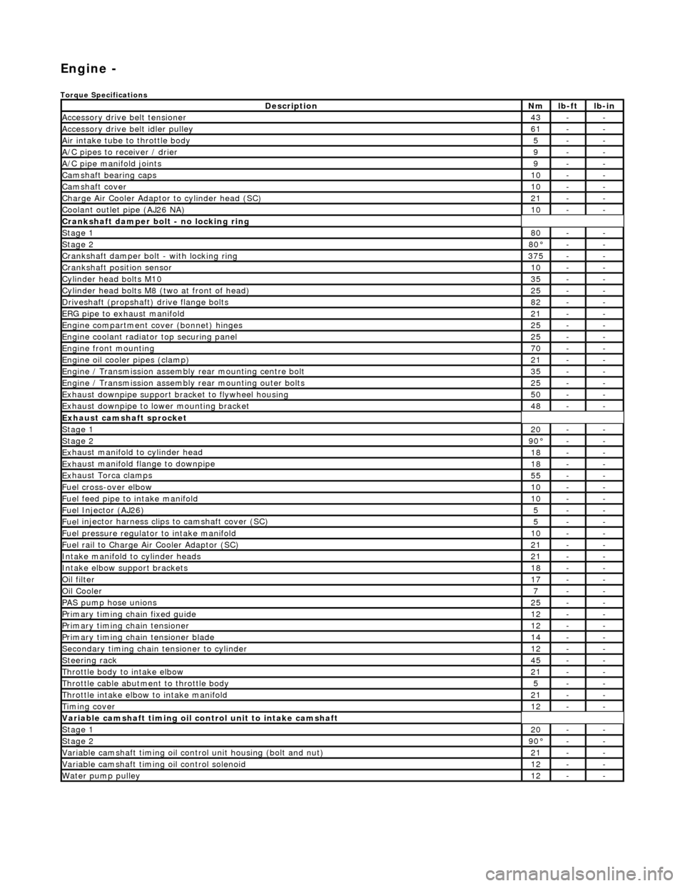
Engi
ne -
Torqu
e Specifications
De
s
cription
Nmlb
-
ft
lb
-
in
A
ccessory
drive belt tensioner
43--
A
ccessory
drive belt idler pulley
61--
Air in
ta
ke tube to throttle body
5--
A/C
pipes t
o receiver / drier
9--
A/C pipe m
anifold joints
9--
Camsh
aft bearin
g caps10--
Ca
msh
aft cove
r10--
Ch
arge Air Co
oler Adaptor to cylinder head (SC)
21--
Co
olan
t outlet pipe (AJ26 NA)
10--
Cran
kshaft damper bolt - no lockin
g ring
St
ag
e 1
80--
Stag
e 2
80°--
C
r
ankshaft damper bolt - with locking ring
37
5--
Cra
nkshaft position sensor
10--
Cy
li
nder head bolts M10
35--
Cy
lin
der head bolts M8 (two at front of head)
25--
Driv
es
haft (propshaft) drive flan
ge bo
l
ts
82--
ERG p
i
pe to exhaust manifold
21--
Engi
ne compartment cover (bonnet) hinges
25--
En
gine
coolant radiator top securing panel
25--
E
ng
ine front mounting
70--
En
gine
oil cooler pipes (clamp)
21--
En
gi
ne / Transmission assembly rear mounting centre bolt
35--
En
gi
ne / Transmission assembly rear mounting outer bolts
25--
Ex
ha
ust downpipe support bracket to flywheel housing
50--
Ex
ha
ust downpipe to lower mounting bracket
48--
E
x
haust camshaft sprocket
St
age 120--
Stage 290 °--
Ex
haust manifold to cylinder head
18--
Ex
ha
ust manifold flange to downpipe
18--
E
x
haust Torca clamps
55--
Fuel cross-over elbo
w
10--
Fu
el f
eed pipe to intake manifold
10--
Fuel
Injector (AJ
26)
5--
Fuel
injector ha
rness clips to camshaft cover (SC)
5--
Fu
el p
ressure re
gu
l
ator to intake manifold
10--
F
u
el rail to Char
ge
A
ir Cooler Adaptor (SC)
21--
In
ta
ke manifold to cylinder heads
21--
Inta
ke elbow support brackets
18--
Oil f
i
lter
17--
Oil C
o
oler
7--
P
AS pu
mp hose unions
25--
P
r
imary timing chain fixed guide
12--
P
r
imary timing chain tensioner
12--
Pr
imary timing chain tensioner blade
14--
S
e
condary timing chain tensioner to cylinder
12--
S
t
eerin
g ra
ck45--
Thro
ttle body to intake elbow
21--
Th
ro
ttle cable abutment to throttle body
5--
Th
ro
ttle intake elbow to intake manifold
21--
Ti
mi
ng cover
12--
Variable camshaft t
i
ming oil control unit to intake camshaft
St
ag
e 1
20--
St
ag
e 2
90
°--
Var
iable camshaft timing oil control unit housing (bolt and nut)
21--
Va
ria
ble camshaft timi
ng oil control solenoid
12--
Wa
ter pump pulley
12--
Page 552 of 2490
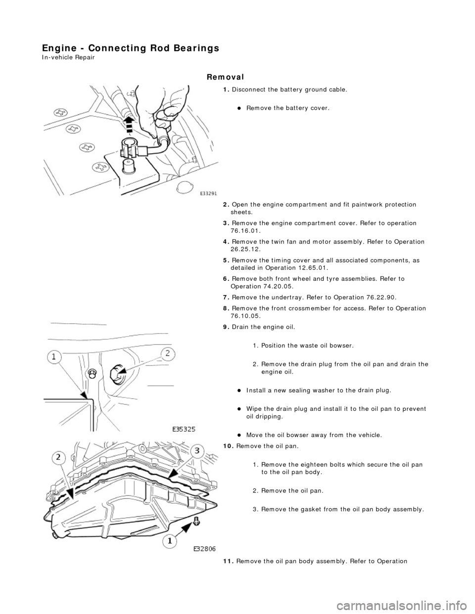
Engine - Connecting Rod Bearings
In-vehic
le Repair
Remov
a
l
1.
Disc
onnect the batt
ery ground cable.
Re
move the battery cover.
2. Open the engine compartment and fit paintwork protection
sheets.
3. Remove the engine compartmen t cover. Refer to operation
76.16.01.
4. Remove the twin fan and motor assembly. Refer to Operation
26.25.12.
5. Remove the timing cover and al l associated components, as
detailed in Operation 12.65.01.
6. Remove both front wheel and tyre assemblies. Refer to
Operation 74.20.05.
7. Remove the undertray. Re fer to Operation 76.22.90.
8. Remove the front crossmember fo r access. Refer to Operation
76.10.05.
9. Drai
n the engine oil.
1. Position the waste oil bowser.
2. Remove the drain plug from the oil pan and drain the engine oil.
Install a new sealing wash er to the
drain plug.
Wipe the drain plug an
d
install
it to the oil pan to prevent
oil dripping.
Move the oil bowser away f
rom the vehicle.
10 . Re
move the oil pan.
1. Remove the eighteen bolt s which secure the oil pan
to the oil pan body.
2. Remove the oil pan.
3. Remove the gasket from the oil pan body assembly.
11. Remove the oil pan body a ssembly. Refer to Operation
Page 555 of 2490

I
nstallation
Tigh
ten each bolt to 8 to 12 Nm initial torque value.
Ti
ghten to a final torque of 57 to 63 Nm.
27. Check that the cranks haft turns freely.
28. Repeat the previous operations for each connecting rod
bearing as necessary.
1. Install the oil pan bo dy assembly. Refer to Operation 12.60.48.
2. Po
sition and align the oil pan gasket to the oil pan body
assembly.
Inse
rt the seal into the locating positions in the groove,
working around from a corner.
Press in the remai
nder of th
e seal, following the same
procedure.
3. Install th
e oil pan to the oil pan body.
1. Position and align the oil pan.
2. Install, but do not tighte n, all eighteen bolts which
secure the oil pan.
4. Tigh
ten the bolts to the correct
torque figure 11-13 Nm, in the
sequence indicated.
Tigh
ten the drain plug to 30-40 Nm.
Install a new oil
filter.
Page 622 of 2490

2. In
stall the camshaft caps to their respective locations (inlet 0 to 4
and exhaust 5 to 9 from the front) and in the correct orientation
(arrow to front of engine).
3. Install and tighten the cap securing bolts. Tighten evenly, in stages, to 10 Nm.
19. Install the camshaft locking tool 303 - 530, align the camshafts as
necessary.
20 . Install the chain guide
.
The
c
hain guide must be installed so that the slotted hole is towards
the top, and the rais ed shoulder to the cylinder block.
1. Install the chain guide to the block and locate it onto the upper retaining pin.
2. Install the retaining bolt and tighten it to 12 Nm.
21. P
ush the secondary chain tensioner piston into the body to provide
clearance for installing the chain.
1. Insert a thin rigid wire through the hole in the end of the tensioner
piston to displace the ball from the non-return valve seat.
2. With the wire in position, press the piston fully into the tensioner body.
Rem
ove the wire.
22 . Ins
tall the secondary chain tensioner to the engine.
1. Fully seat the tensioner to the cylinder head.
2. Install the two bolts which secure the tensioner and tighten to 12 Nm.
23 . N
OTE: Assemble the VVT unit, the exhaust camshaft sprocket and the
secondary chain, in preparation for installing to the engine.
Install the VVT unit to the engine.
1. Install the above assembly to the camshafts with the chain correctly positioned over the tensioner; VVT unit to the inlet and
the sprocket to the exhaust.
2. Install, but do not tighten, each bolt which secures the VVT unit and the exhaust sprocket to the camshafts.
24. Install the chain tensioning tool 303 - 532 to the exhaust camshaft
sprocket.