body JAGUAR X308 1998 2.G Repair Manual
[x] Cancel search | Manufacturer: JAGUAR, Model Year: 1998, Model line: X308, Model: JAGUAR X308 1998 2.GPages: 2490, PDF Size: 69.81 MB
Page 623 of 2490

Re
position the sprocket (and the VVT unit) for the most advantageous
position for use of the tool.
R
emove the tool.
25
.
Install the primary timing chain.
R
eposition the VVT unit forwards on the cam journal (do not rotate it)
to allow the chain to cl ear the head casting. Disconnect the primary
chain from the Ty-strap.
1. Install the primary chain to position over the crankshaft sprocket and the VVT unit sprocket. There mu st be no slack on the drive
side of the primary chain and the VVT unit must not be rotated on
the camshaft.
26
.
Install the primary chain tensioner blade.
1. Position the tensioner blade to the cylinder block.
2. Install the retaining / pivot bolt and tighten it to 14 Nm.
27
.
Push the primary chain tensioner piston into the body to provide clearance
for installing.
1. Insert a thin rigid wire through the hole in the end of the tensioner
piston to displace the ball from the non-return valve seat.
2. With the wire in position, press the piston fully into the tensioner body.
Re
move the wire.
28
.
Assemble the tensioner.
1. Install the two mounting bolts to the tensioner.
2. Locate the tensioner back-plate to the two bolts.
29. Install the tensioner to the cylinder block.
1. Position and align the tensioner to the cylinder block and to the mating slot on the rear face of the tensioner blade.
2. Install and tighten the two bolts to 12 Nm.
Page 637 of 2490

To th
e upper face of each bearing surface (two places) in the cylinder
head.
To th
e upper face of each bearing surface (two places) in each bearing
cap.
On
the cam lobes ONLY, not on the base circle area.
17
.
Install the camshafts.
1. Install the camshafts to position in the cylinder head, with the timing flats uppermost.
2. Install the camshaft caps to their respective locations (inlet 0 to 4 and exhaust 5 to 9 from the front) and in the correct orientation
(arrow to front of engine).
3. Install and tighten the cap securing bolts. Tighten evenly, in stages, to 10 Nm.
18. Install the camshaft locking tool 303 - 530, align the camshafts as
necessary.
19
.
Install the chain guide.
• NOTE: The chain guide must be installed so that the slotted hole is
towards the top, and the raised shoulder to the cylinder block. 1. Install the chain guide to the block and locate it onto the upper retaining pin.
2. Install the retaining bolt and tighten it to 12 Nm.
20
.
Push the secondary chain tensioner piston into the body to provide
clearance for installing the chain.
1. Insert a thin rigid wire through the hole in the end of the tensioner
piston to displace the ball from the non-return valve seat.
2. With the wire in position, press the piston fully into the tensioner body.
Re
move the wire.
21
.
Install the secondary chain tensioner to the engine.
1. Fully seat the tensioner to the cylinder head.
2. Install the two bolts which secure the tensioner and tighten to 12 Nm.
22. Install the VVT unit to the engine.
A
ssemble the VVT unit, the exhaust camshaft sprocket and the
Page 638 of 2490
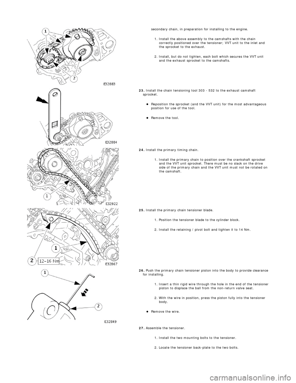
se
condary chain, in preparation for installing to the engine.
1. Install the above assembly to the camshafts with the chain correctly positioned over the tensioner; VVT unit to the inlet and
the sprocket to the exhaust.
2. Install, but do not tighten, each bolt which secures the VVT unit and the exhaust sprocket to the camshafts.
23 .
Install the chain t
ensioning tool 303 - 532 to the exhaust camshaft
sprocket.
Re p
osition the sprocket (and the VVT unit) for the most advantageous
position for use of the tool.
Re
move the tool.
24 . Install the
primary timing chain.
1. Install the primary chain to position over the crankshaft sprocket and the VVT unit sprocket. There mu st be no slack on the drive
side of the primary chain and the VVT unit must not be rotated on
the camshaft.
25 . Install the pri
mary chain tensioner blade.
1. Position the tensioner blade to the cylinder block.
2. Install the retaining / pivot bolt and tighten it to 14 Nm.
26 . P
ush the primary chain tensioner piston into the body to provide clearance
for installing.
1. Insert a thin rigid wire through the hole in the end of the tensioner
piston to displace the ball from the non-return valve seat.
2. With the wire in position, press the piston fully into the tensioner body.
Rem
ove the wire.
27. Assemble the tensioner.
1. Install the two mounting bolts to the tensioner.
2. Locate the tensioner back-plate to the two bolts.
Page 643 of 2490
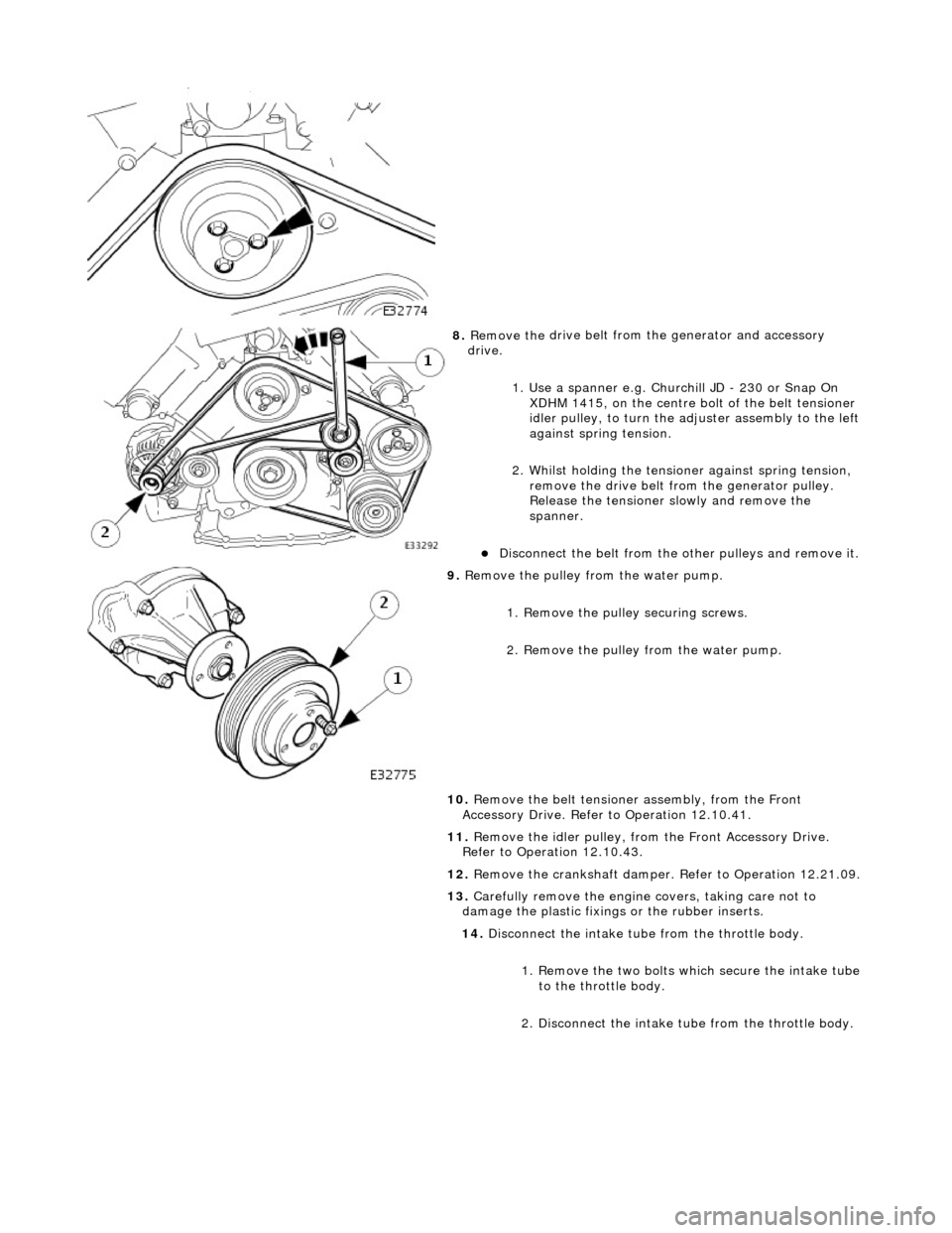
8. Remove the
drive belt from
the generator and accessory
drive.
1. Use a spanner e.g. Churchill JD - 230 or Snap On XDHM 1415, on the centre bo lt of the belt tensioner
idler pulley, to turn the adju ster assembly to the left
against spring tension.
2. Whilst holding the tensioner against spring tension, remove the drive belt from the generator pulley.
Release the tensioner sl owly and remove the
spanner.
D
isconnect the belt from the
other pulleys and remove it.
9. Re
move the pulley from the water pump.
1. Remove the pulley securing screws.
2. Remove the pulley from the water pump.
10. Remove the belt tensione r assembly, from the Front
Accessory Drive. Refer to Operation 12.10.41.
11. Remove the idler pulley, from the Front Accessory Drive.
Refer to Operation 12.10.43.
12. Remove the crankshaft damper. Refer to Operation 12.21.09.
13. Carefully remove the engine covers, taking care not to
damage the plasti c fixings or the rubber inserts.
14. Disconnect the intake tube from the throttle body.
1. Remove the two bolts which secure the intake tube to the throttle body.
2. Disconnect the intake tube from the throttle body.
Page 644 of 2490
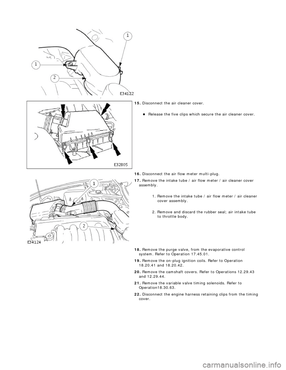
15. Di
sconnect the air cleaner cover.
R
e
lease the five clips which se
cure the air cleaner cover.
16. Disconnect the air flow meter multi-plug.
17 . R
emove the intake tube / air
flow meter / air cleaner cover
assembly.
1. Remove the intake tube / air flow meter / air cleaner
cover assembly.
2. Remove and discard the ru bber seal; air intake tube
to throttle body.
18. Remove the purge valve, fro m the evaporative control
system. Refer to Operation 17.45.01.
19. Remove the on-plug ignition coils. Refer to Operation
18.20.41 and 18.20.42.
20. Remove the camshaft covers. Refer to Operations 12.29.43
and 12.29.44.
21. Remove the variable valve ti ming solenoids. Refer to
Operation18.30.63.
22. Disconnect the engine harness retaining clips from the timing
cover.
Page 648 of 2490
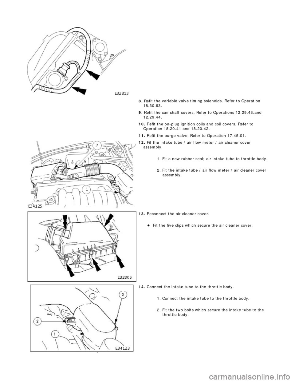
8. Re
fit the variable valve timing
solenoids. Refer to Operation
18.30.63.
9. Refit the camshaft covers. Refer to Operations 12.29.43.and
12.29.44.
10. Refit the on-plug ignition coils and coil covers. Refer to
Operation 18.20.41 and 18.20.42.
11. Refit the purge valve. Refer to Operation 17.45.01.
12 . F
it the intake tube / air flow meter / air cleaner cover
assembly.
1. Fit a new rubber seal; air in take tube to throttle body.
2.
Fit the intake tube / air
flow meter / air cleaner cover
assembly.
13 . R
econnect the air cleaner cover.
F
it
the five clips which secu
re the air cleaner cover.
14. Co
nnect the intake tube to the throttle body.
1. Connect the intake tube to the throttle body.
2. Fit the two bolts which secure the intake tube to the throttle body.
Page 652 of 2490
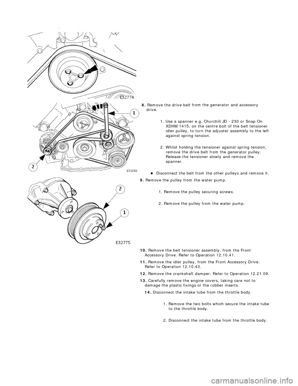
8. Remove the drive belt
from
the generator and accessory
drive.
1. Use a spanner e.g. Churchill JD - 230 or Snap On XDHM 1415, on the centre bo lt of the belt tensioner
idler pulley, to turn the adju ster assembly to the left
against spring tension.
2. Whilst holding the tensioner against spring tension, remove the drive belt from the generator pulley.
Release the tensioner sl owly and remove the
spanner.
D i
sconnect the belt from the
other pulleys and remove it.
9. Remove t
he pulley from the water pump.
1. Remove the pulley securing screws.
2. Remove the pulley from the water pump.
10. Remove the belt tensione r assembly, from the Front
Accessory Drive. Refer to Operation 12.10.41.
11. Remove the idler pulley, from the Front Accessory Drive.
Refer to Operation 12.10.43.
12. Remove the crankshaft damper. Refer to Operation 12.21.09.
13. Carefully remove the engine covers, taking care not to
damage the plasti c fixings or the rubber inserts.
14. Disconnect the intake tube from the throttle body.
1. Remove the two bolts which secure the intake tube to the throttle body.
2. Disconnect the intake tube from the throttle body.
Page 653 of 2490
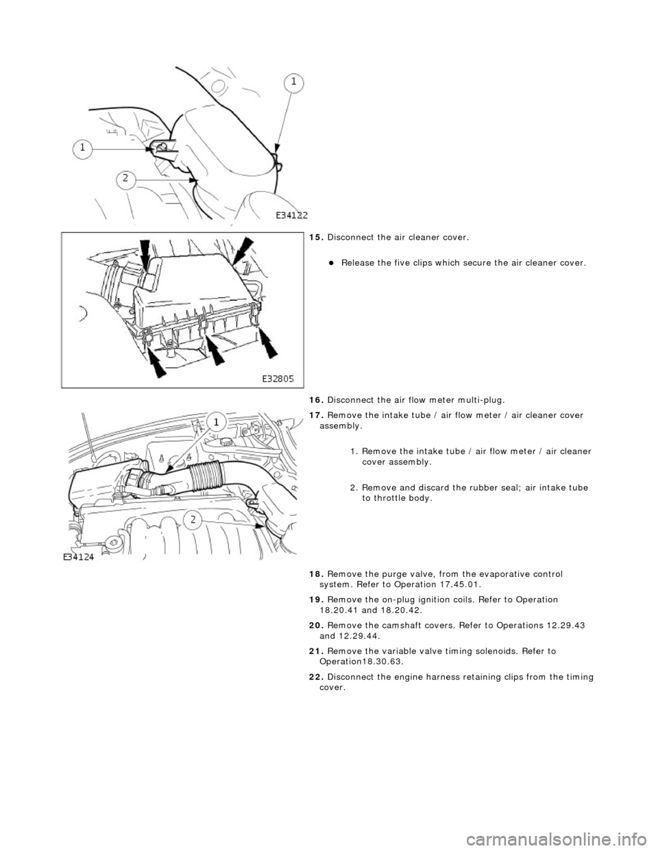
15
.
Disconnect the air cleaner cover.
R
elease the five clips which se
cure the air cleaner cover.
16. Disconnect the air flow meter multi-plug.
17
.
Remove the intake tube / air flow meter / air cleaner cover
assembly.
1. Remove the intake tube / air flow meter / air cleaner
cover assembly.
2. Remove and discard the ru bber seal; air intake tube
to throttle body.
18. Remove the purge valve, fro m the evaporative control
system. Refer to Operation 17.45.01.
19. Remove the on-plug ignition coils. Refer to Operation
18.20.41 and 18.20.42.
20. Remove the camshaft covers. Refer to Operations 12.29.43
and 12.29.44.
21. Remove the variable valve ti ming solenoids. Refer to
Operation18.30.63.
22. Disconnect the engine harness retaining clips from the timing
cover.
Page 657 of 2490
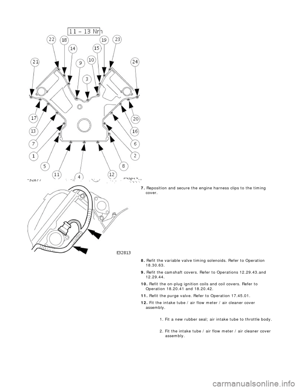
7. Reposition and secure the engine harness clips to the timing
cover.
8. Refit the variable valve timing solenoids. Refer to Operation
18.30.63.
9. Refit the camshaft covers. Refer to Operations 12.29.43.and
12.29.44.
10. Refit the on-plug ignition coils and coil covers. Refer to
Operation 18.20.41 and 18.20.42.
11. Refit the purge valve. Refer to Operation 17.45.01.
12. Fit the intake tube / air flow meter / air cleaner cover
assembly.
1. Fit a new rubber seal; air in take tube to throttle body.
2. Fit the intake tube / air flow meter / air cleaner cover
assembly.
Page 658 of 2490
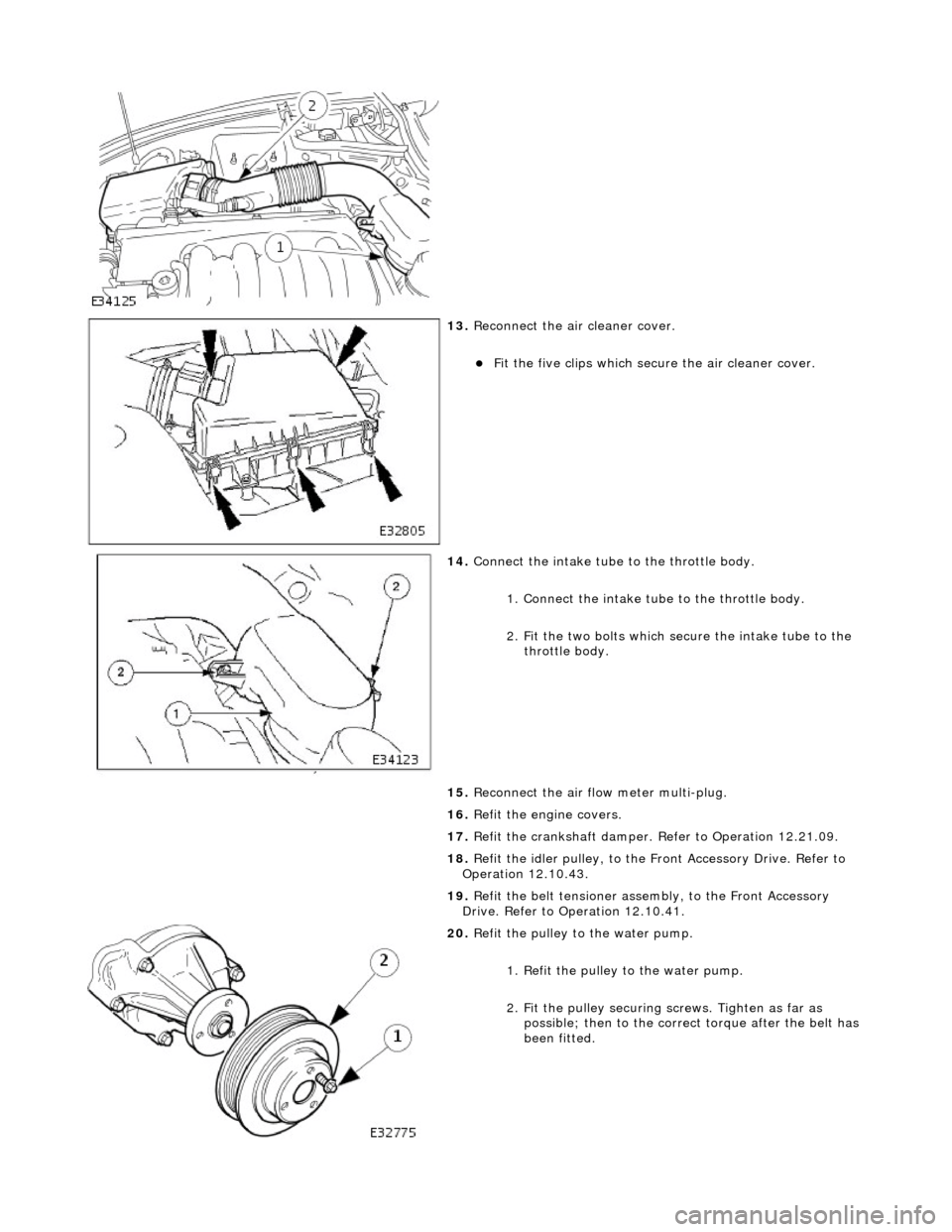
13. Reconnect the air cleaner cover.
Fit the five clips which secu re the air cleaner cover.
14. Connect the intake tube to the throttle body.
1. Connect the intake tube to the throttle body.
2. Fit the two bolts which secure the intake tube to the throttle body.
15. Reconnect the air flow meter multi-plug.
16. Refit the engine covers.
17. Refit the crankshaft damper. Refer to Operation 12.21.09.
18. Refit the idler pulley, to the Front Accessory Drive. Refer to
Operation 12.10.43.
19. Refit the belt tensioner assembly, to the Front Accessory
Drive. Refer to Operation 12.10.41.
20. Refit the pulley to the water pump.
1. Refit the pulley to the water pump.
2. Fit the pulley securing screws. Tighten as far as
possible; then to the correct torque after the belt has
been fitted.