electrical JAGUAR X308 1998 2.G Service Manual
[x] Cancel search | Manufacturer: JAGUAR, Model Year: 1998, Model line: X308, Model: JAGUAR X308 1998 2.GPages: 2490, PDF Size: 69.81 MB
Page 438 of 2490
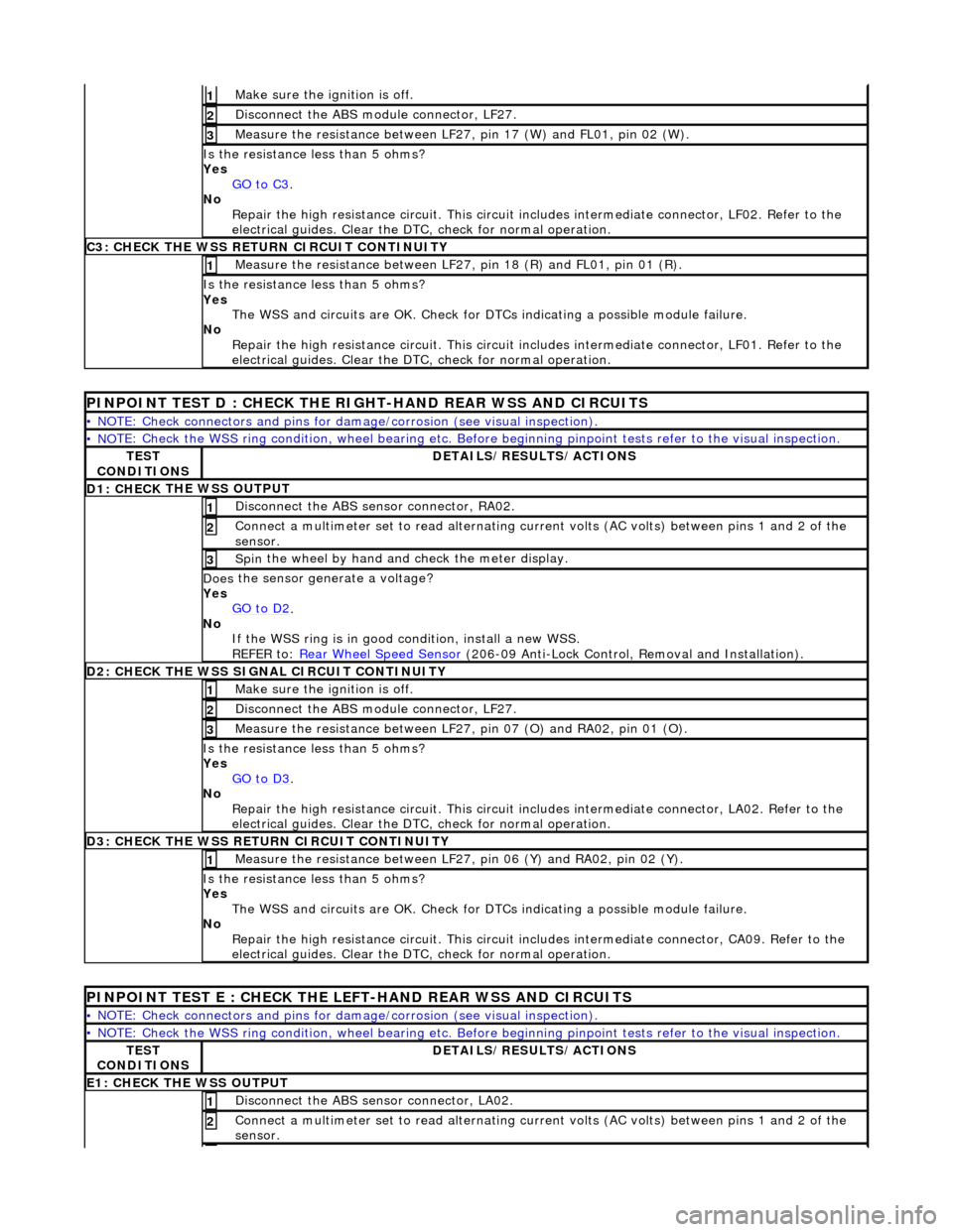
Make sure the ignition is off. 1
Disc
onnect the ABS module connector, LF27.
2
M
e
asure the resistance between LF27, pin 17 (W) and FL01, pin 02 (W).
3
I
s
the resistance less than 5 ohms?
Yes GO to C3
.
No
Re
pair the high resistance circui
t. This circuit includes intermed iate connector, LF02. Refer to the
electrical guides. Clear the DTC, check for normal operation.
C3: CH
ECK THE WSS RETURN CIRCUIT CONTINUITY
Measure
the resistance between LF27, pin 18 (R) and FL01, pin 01 (R).
1
Is
the resistance less than 5 ohms?
Yes The WSS and circuits are OK. Check for DTCs indicating a possible module failure.
No Repair the high resistance circui t. This circuit includes intermediate connector, LF01. Refer to the
electrical guides. Clear the DTC, check for normal operation.
PI
NPOINT TEST D : CHECK THE RIGH
T-HAND REAR WSS AND CIRCUITS
•
NOTE: Check connectors and pins for damage/corrosion
(see visual inspection).
• NO
TE: Check the WSS ring condition, whee
l bearing etc. Before beginning pinpoint test s refer to the visual inspection.
TES
T
CONDITIONS
D E
TAILS/RESULTS/ACTIONS
D1: CHECK
THE WSS OUTPUT
Disc
onne
ct the ABS sensor connector, RA02.
1
Connec
t
a multimeter set
to read alternating curr ent volts (AC volts) between pins 1 and 2 of the
sensor.
2
Spin
the wheel by hand and check the meter display.
3
Doe
s
the sensor generate a voltage?
Yes GO to D2
.
No
If
the WSS ring is in good condition, install a new WSS.
REFER to: Rear Wheel Speed Sensor
(206-0
9 Anti-Lock Control, Removal and Installation).
D
2
: CHECK THE WSS SIGNAL CIRCUIT CONTINUITY
Make sure the ignition is off. 1
Disc
onnect the ABS module connector, LF27.
2
Measure t
he resistance between LF27
, pin 07 (O) and RA02, pin 01 (O).
3
Is
the resistance less than 5 ohms?
Yes GO to D3
.
No Re
pair the high resistance circui
t. This circuit includes intermed iate connector, LA02. Refer to the
electrical guides. Clear the DTC, check for normal operation.
D3:
CHECK THE WSS RETURN CIRCUIT CONTINUITY
Meas
ure t
he resistance between LF27
, pin 06 (Y) and RA02, pin 02 (Y).
1
Is
the resistance less than 5 ohms?
Yes The WSS and circuits are OK. Check for DTCs indicating a possible module failure.
No Repair the high resistance circui t. This circuit includes intermediate connector, CA09. Refer to the
electrical guides. Clear the DTC, check for normal operation.
PI
NPOINT TEST E : CHECK THE LEFT-HAND REAR WSS AND CIRCUITS
•
NOTE: Check connectors and pins for damage/corrosion
(see visual inspection).
• NO
TE: Check the WSS ring condition, whee
l bearing etc. Before beginning pinpoint test s refer to the visual inspection.
TES
T
CONDITIONS
D E
TAILS/RESULTS/ACTIONS
E1
: CHECK THE W
SS OUTPUT
Disc
onne
ct the ABS sensor connector, LA02.
1
Connec
t
a multimeter set
to read alternating curr ent volts (AC volts) between pins 1 and 2 of the
sensor.
2
Page 439 of 2490
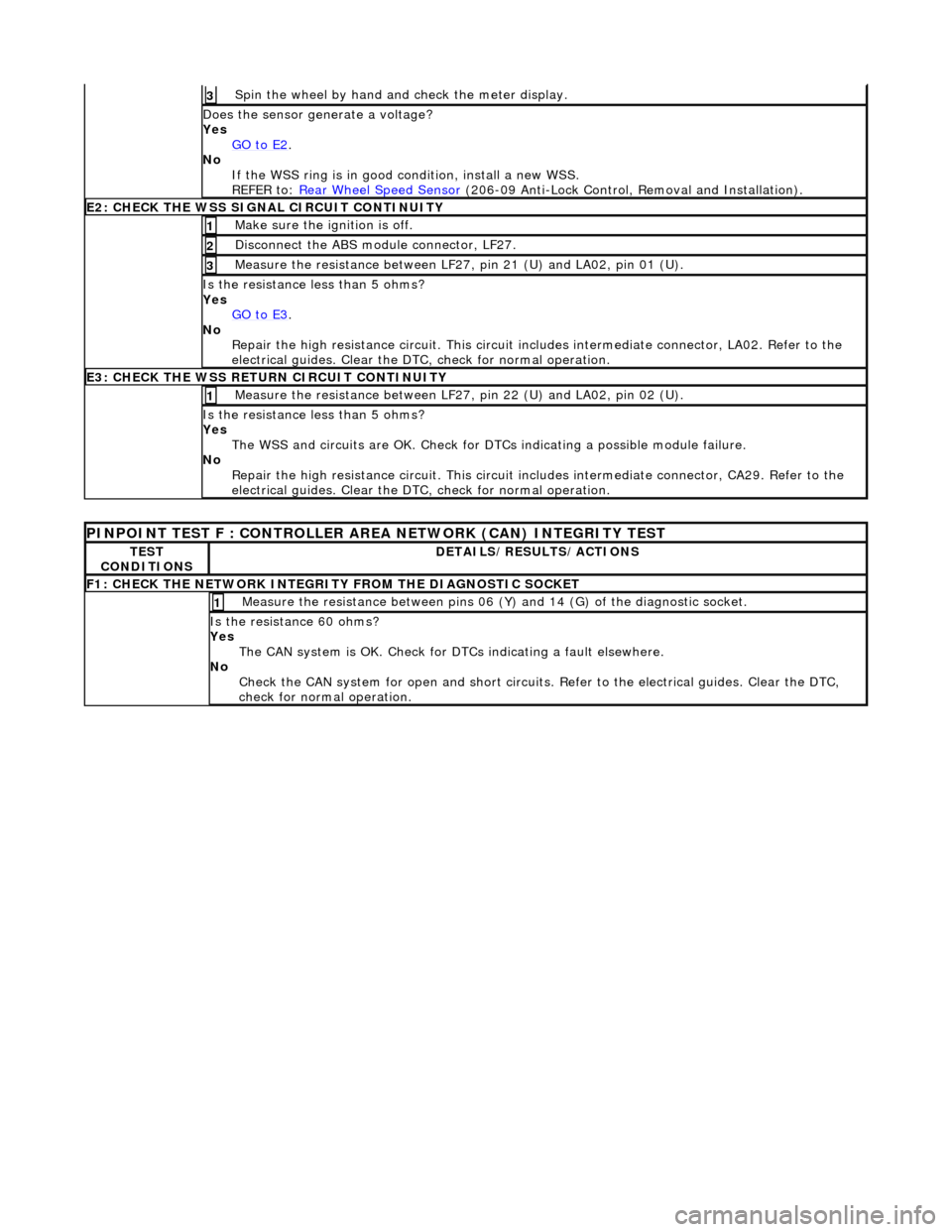
Spin
the wheel by hand and check the meter display.
3
Doe
s the sensor generate a voltage?
Yes GO to E2
.
No
If the WSS ring is in good condition, install a new WSS.
REFER to: Rear Wheel Speed Sensor
(20
6-09 Anti-Lock Control, Removal and Installation).
E2
: CHECK THE WSS SIGNAL CIRCUIT CONTINUITY
Make sure the ignition is off. 1
Di
sconnect the ABS module connector, LF27.
2
Meas
ure the resistance between LF27
, pin 21 (U) and LA02, pin 01 (U).
3
I
s the resistance less than 5 ohms?
Yes GO to E3
.
No
Repair the high resistance circui t. This circuit includes intermediate connector, LA02. Refer to the
electrical guides. Clear the DTC, check for normal operation.
E3
: CHECK THE WSS RETURN CIRCUIT CONTINUITY
Meas
ure the resistance between LF27
, pin 22 (U) and LA02, pin 02 (U).
1
I
s the resistance less than 5 ohms?
Yes The WSS and circuits are OK. Check for DTCs indicating a possible module failure.
No Repair the high resistance circui t. This circuit includes intermediate connector, CA29. Refer to the
electrical guides. Clear the DTC, check for normal operation.
P
INPOINT TEST F : CONT
ROLLER AREA NETWORK (CAN) INTEGRITY TEST
TE
ST
CONDITIONS
D
ETAILS/RESULTS/ACTIONS
F
1: CHECK THE NETWORK INTEGRITY
FROM THE DIAGNOSTIC SOCKET
M
easure the resistance between pins 06 (Y) and 14 (G) of the diagnostic socket.
1
I
s the resistance 60 ohms?
Yes The CAN system is OK. Check for DTCs indicating a fault elsewhere.
No Check the CAN system for open an d short circuits. Refer to the electrical guides. Clear the DTC,
check for normal operation.
Page 441 of 2490
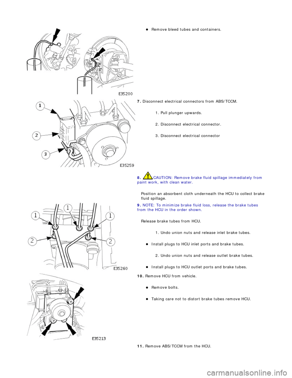
пЃ¬Remove bleed tub
es and containers.
7. Disc
onnect electrical connectors from ABS/TCCM.
1. Pull plunger upwards.
2. Disconnect electrical connector.
3. Disconnect electrical connector
8. CAUTION: Remove brake flui d spillage immediately from
paint work, with clean water.
Position an absorbent cloth under neath the HCU to collect brake
fluid spillage.
9. NOTE
: To minimize brake fluid
loss, release the brake tubes
from the HCU in the order shown.
Release brake tubes from HCU.
1. Undo union nuts and re lease inlet brake tubes.
пЃ¬Install plugs to HCU inlet por
ts and brake tubes.
2. Undo union nuts and re lease outlet brake tubes.
пЃ¬Inst
all plugs to HCU outlet
ports and brake tubes.
10
.
Remove HCU from vehicle.
пЃ¬Re
move bolts.
пЃ¬T
aking care not to distort
brake tubes remove HCU.
11. Remove ABS/TCCM from the HCU.
Page 442 of 2490
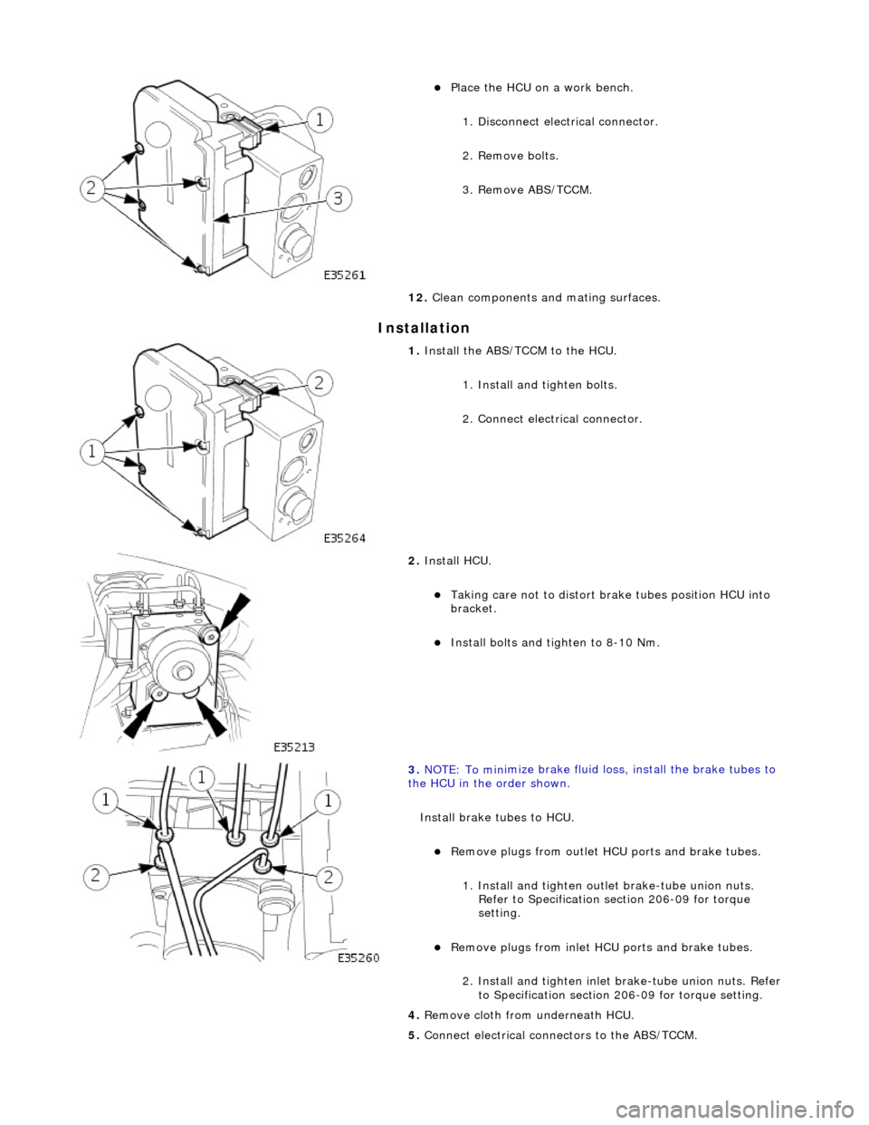
In
stallation
пЃ¬Pla
ce the HCU on a work bench.
1. Disconnect electrical connector.
2. Remove bolts.
3. Remove ABS/TCCM.
12. Clean components and mating surfaces.
1. Install th e AB
S/TCCM to the HCU.
1. Install and tighten bolts.
2. Connect electrical connector.
2. Install HCU.
пЃ¬Takin g
care not to distort brake tubes position HCU into
bracket.
пЃ¬Install bolts and tighten to 8-1
0 Nm.
3. NOTE : To min
imize brake fluid lo
ss, install the brake tubes to
the HCU in the order shown.
Install brake tubes to HCU.
пЃ¬Re
move plugs from outlet HC
U ports and brake tubes.
1. Install and tighten outl et brake-tube union nuts.
Refer to Specification section 206-09 for torque
setting.
пЃ¬Re mo
ve plugs from inlet HC
U ports and brake tubes.
2. Install and tighten inlet brake-tube union nuts. Refer to Specification section 206-09 for torque setting.
4. Remove cloth from underneath HCU.
5. Connect electrical connectors to the ABS/TCCM.
Page 443 of 2490
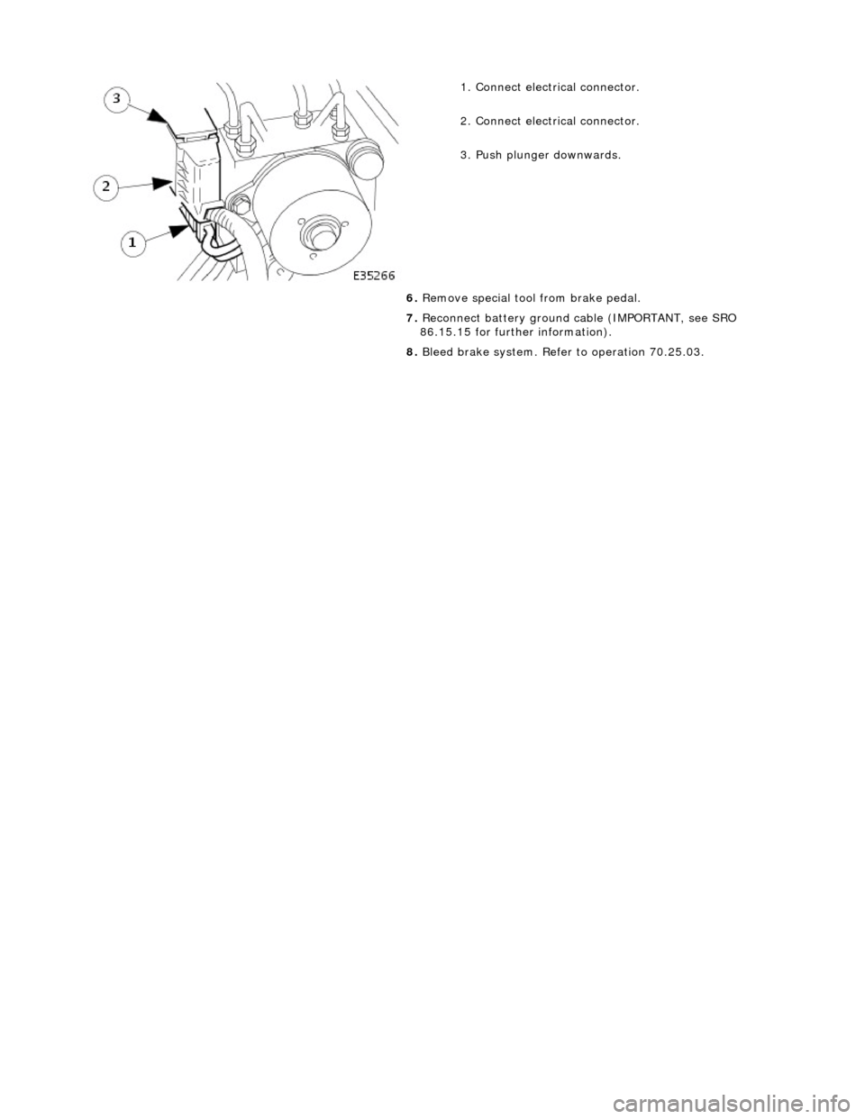
1.
Connect electrical connector.
2. Connect electrical connector.
3. Push plunger downwards.
6. Remove special tool from brake pedal.
7. Reconnect battery ground cable (IMPORTANT, see SRO
86.15.15 for further information).
8. Bleed brake system. Refer to operation 70.25.03.
Page 446 of 2490
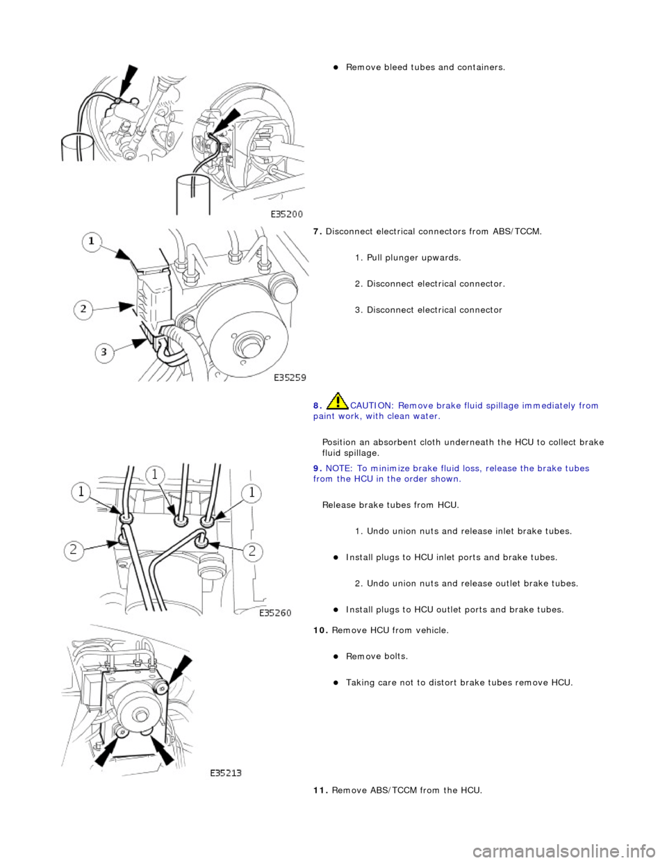
пЃ¬Remove bleed tube
s and containers.
7. Disc onne
ct electrical connectors from ABS/TCCM.
1. Pull plunger upwards.
2. Disconnect electrical connector.
3. Disconnect electrical connector
8. CAUTION: Remove brake flui d spillage immediately from
paint work, with clean water.
Position an absorbent cloth under neath the HCU to collect brake
fluid spillage.
9. NOTE : To min
imize brake fluid loss, release the brake tubes
from the HCU in the order shown.
Release brake tubes from HCU.
1. Undo union nuts and re lease inlet brake tubes.
пЃ¬Install plugs to HCU inlet por t
s and brake tubes.
2. Undo union nuts and re lease outlet brake tubes.
пЃ¬Instal
l plugs to HCU outlet
ports and brake tubes.
10 . R
emove HCU from vehicle.
пЃ¬Re
mo
ve bolts.
пЃ¬T
a
king care not to distort
brake tubes remove HCU.
11. Remove ABS/TCCM from the HCU.
Page 447 of 2490
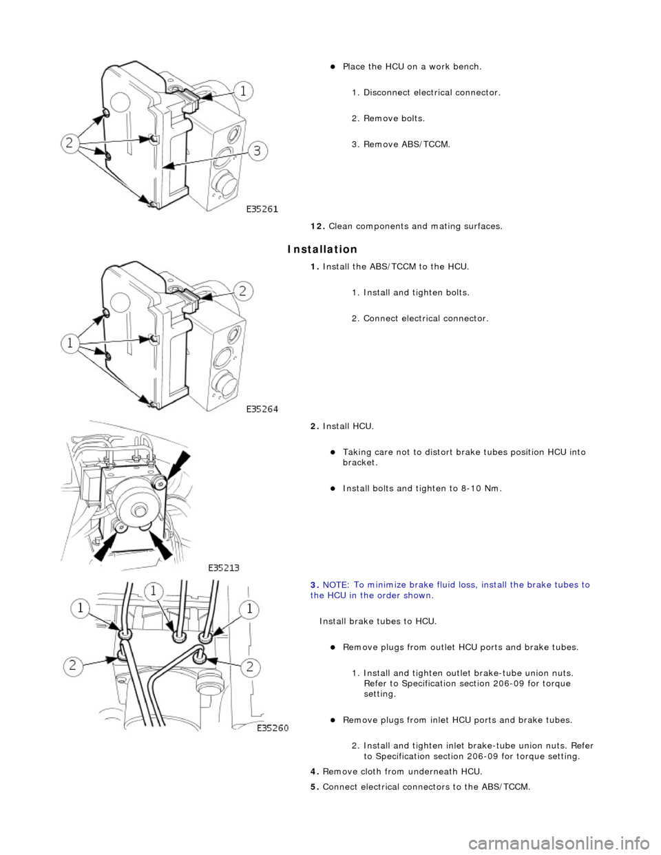
I
nstallation
пЃ¬Pl
ace the HCU on a work bench.
1. Disconnect electrical connector.
2. Remove bolts.
3. Remove ABS/TCCM.
12. Clean components and mating surfaces.
1. Install th
e ABS/TCCM to the HCU.
1. Install and tighten bolts.
2. Connect electrical connector.
2. Install HCU.
пЃ¬Takin
g care not to distort brake tubes position HCU into
bracket.
пЃ¬Install bolts an
d tighten to 8-10 Nm.
3. NOTE
: To minimize brake fluid lo
ss, install the brake tubes to
the HCU in the order shown.
Install brake tubes to HCU.
пЃ¬R
emove plugs from outlet HC
U ports and brake tubes.
1. Install and tighten outl et brake-tube union nuts.
Refer to Specification section 206-09 for torque
setting.
пЃ¬Re
move plugs from inlet HC
U ports and brake tubes.
2. Install and tighten inlet brake-tube union nuts. Refer to Specification section 206-09 for torque setting.
4. Remove cloth from underneath HCU.
5. Connect electrical connectors to the ABS/TCCM.
Page 448 of 2490
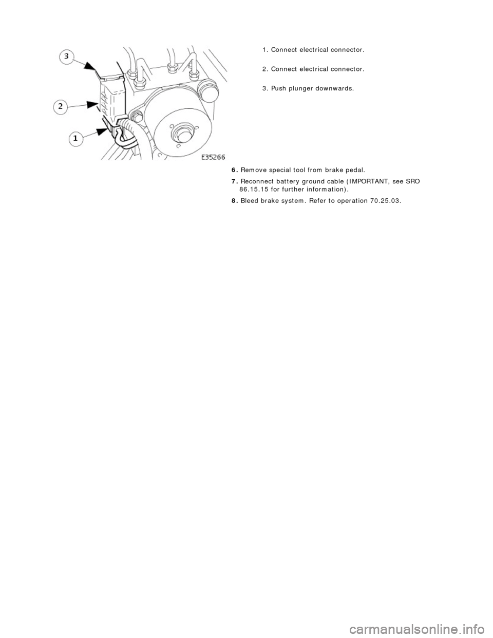
1. Conne
ct electrical connector.
2. Connect electrical connector.
3. Push plunger downwards.
6. Remove special tool from brake pedal.
7. Reconnect battery ground cable (IMPORTANT, see SRO
86.15.15 for further information).
8. Bleed brake system. Refer to operation 70.25.03.
Page 455 of 2490
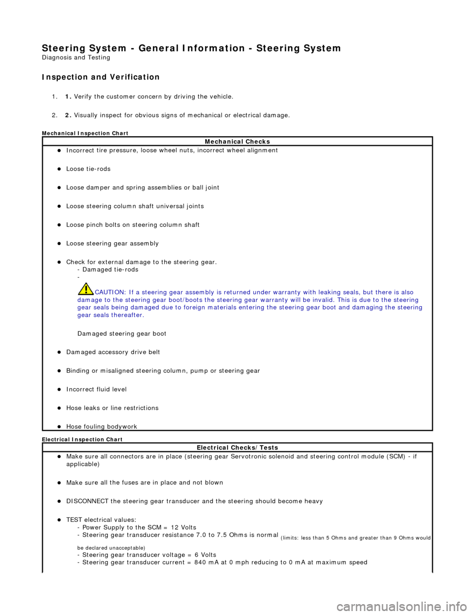
Steering System - General Inform
ation - Steering System
D
iagnosis and Testing
I
nspection and Verification
1.
1. Verify t
he customer concern by driving the vehicle.
2. 2. Visually inspect for obvious signs of mechanical or electrical damage.
Mec
hanical Inspection Chart
Electrical Inspection Chart
Mechanical Checks
пЃ¬Incorrect
tire pressure, loose whee
l nuts, incorrect wheel alignment
пЃ¬Loose ti
e-rods
пЃ¬Loose dam
per and spring assemblies or ball joint
пЃ¬Loose s
teering column shaft universal joints
пЃ¬Loose pinc
h bolts on steering column shaft
пЃ¬Loose steeri
ng gear assembly
пЃ¬Check f
or external damage to the steering gear.
- Damaged tie-rods
-
CAUTION: If a steering gear assemb ly is returned under warranty with leaking seals, but there is also
damage to the steering gear boot/boots the steering gear warranty will be invalid. This is due to the steering
gear seals being damaged due to fore ign materials entering the steering gear boot and damaging the steering
gear seals thereafter.
Damaged steering gear boot
пЃ¬Damaged accessory driv
e belt
пЃ¬Bin
ding or misaligned steering co
lumn, pump or steering gear
пЃ¬Incorrect fluid
level
пЃ¬Hose leaks o
r line restrictions
пЃ¬Hose fou
ling bodywork
El
ectrical Checks/Tests
пЃ¬Make sure all
connectors are in plac
e (steering gear Servotronic solenoid and steering control module (SCM) - if
applicable)
пЃ¬Make su
re all the fuses are in place and not blown
пЃ¬D
ISCONNECT the steering gear transducer
and the steering should become heavy
пЃ¬TEST e
lectrical values:
- Power Supply to the SCM = 12 Volts
- Steering gear transducer resist ance 7.0 to 7.5 Ohms is normal
(
limits: less than 5 Ohms and greater than 9 Ohms would
be declared unacceptable)
- Steeri
ng gear transducer voltage = 6 Volts
- Steering gear transducer cu rrent = 840 mA at 0 mph reducing to 0 mA at maximum speed
Page 456 of 2490
3.3. If an obvi
ous cause for an observed or
reported concern is found, correct th e cause (if possible) before proceeding
to the next step.
4. 4. Check the power steering fluid condit ion. For additional information, REFER to Power Steering Fluid Condition
Check in this section.
5. 5. If the concern is not visually evid ent, verify the symptom and REFER to Steering Fault Diagnosis by Symptom
Charts in this section.
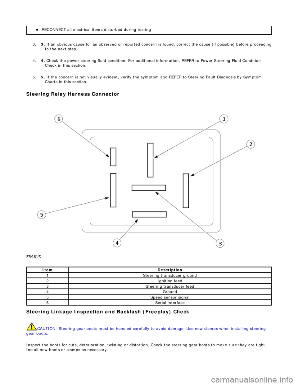
Steering Re
lay Harness Connector
Stee
ring Linkage In
spection and Backlash (Freeplay) Check
CAUTIO
N: Steering gear boots must be
handled carefully to avoid damage. Use new clamps when installing steering
gear boots.
Inspect the boots for cuts, deterioration, tw isting or distortion. Check the steering gear boots to make sure they are tight.
Install new boots or clamps as necessary.
пЃ¬REC O
NNECT all electrical item
s disturbed during testing
Ite
m
De
scr
iption
1Ste
e
rin
g tran
sduc
er
ground
2Igni
ti
on feed
3Steeri
ng transducer feed
4Ground
5Speed s
ensor signal
6Seri
a
l interface