electrical JAGUAR X308 1998 2.G Owner's Guide
[x] Cancel search | Manufacturer: JAGUAR, Model Year: 1998, Model line: X308, Model: JAGUAR X308 1998 2.GPages: 2490, PDF Size: 69.81 MB
Page 204 of 2490
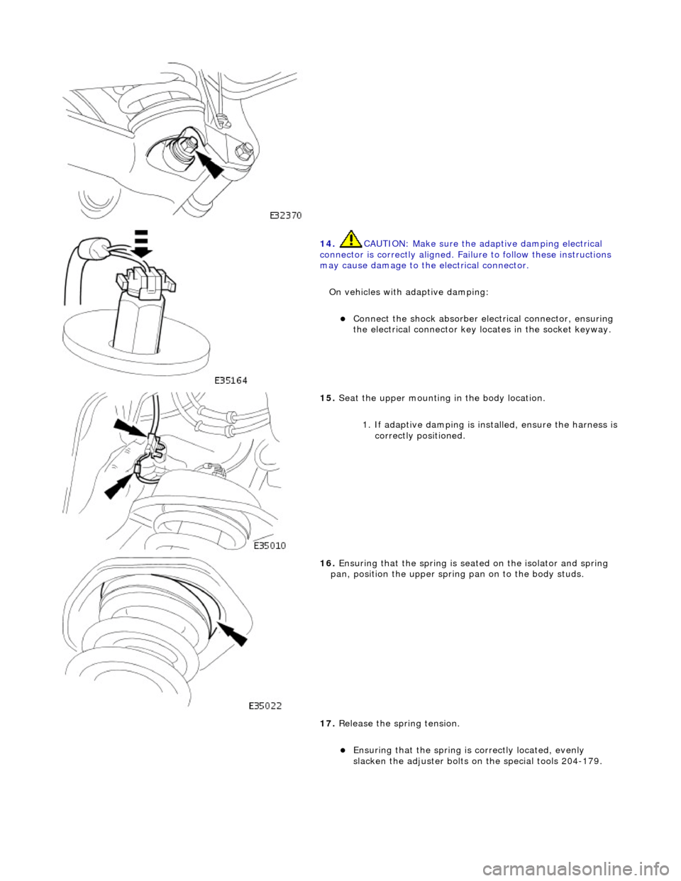
14. CAUTI
ON: Make sure the adaptive damping electrical
connector is correctly aligned. Failu re to follow these instructions
may cause damage to the electrical connector.
On vehicles with adaptive damping:
пЃ¬Conne ct
the shock absorber elec
trical connector, ensuring
the electrical connector key locates in the socket keyway.
15 . Seat
the upper mounting in the body location.
1. If adaptive damping is installed, ensure the harness is
correctly positioned.
16 . Ensuri
ng that the spri
ng is seated on the isolator and spring
pan, position the u pper spring pan on to the body studs.
17. Release the spring tension.
пЃ¬Ensuring that the spri
ng is
correctly located, evenly
slacken the adjuster bolts on the special tools 204-179.
Page 206 of 2490
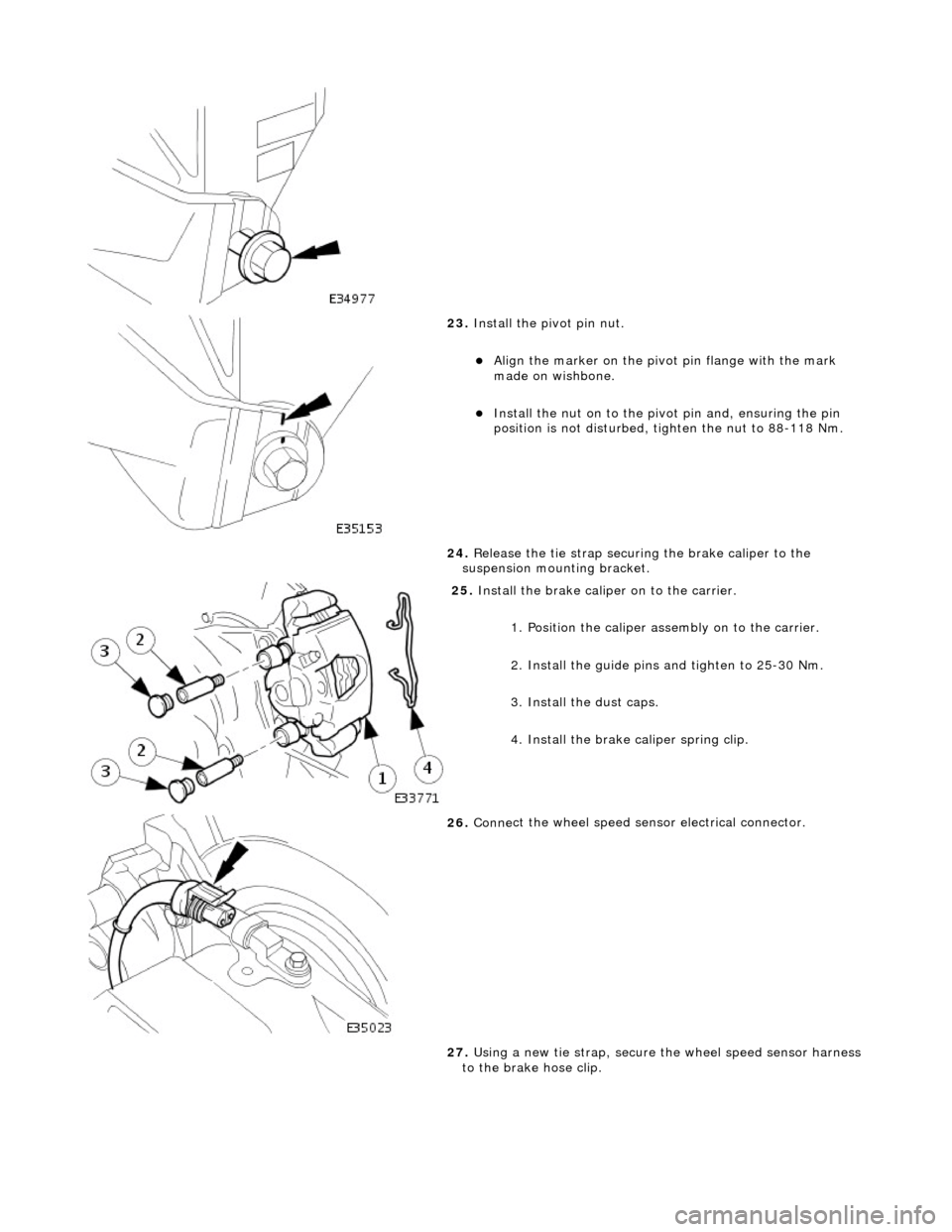
23. Inst
all the pivot pin nut.
пЃ¬Ali
g
n the marker on the pivo
t pin flange with the mark
made on wishbone.
пЃ¬Inst al
l the nut on to the pivot pin and, ensuring the pin
position is not dist urbed, tighten the nut to 88-118 Nm.
24. Release the tie strap securing the brake caliper to the
suspension mounting bracket.
25 . Install
the brake caliper on to the carrier.
1. Position the caliper asse mbly on to the carrier.
2. Install the guide pins and tighten to 25-30 Nm.
3. Install the dust caps.
4. Install the brake caliper spring clip.
26 . Conne
ct the wheel speed sensor electrical connector.
27. Using a new tie strap, secure the wheel speed sensor harness
to the brake hose clip.
Page 278 of 2490
Vehicle Dynamic Suspension - Vehicle Dynamic Suspension
Diagn
osis and Testing
Refer to the PDU User Guide for details of diagnosing and testing the Adaptive Damping System. The PDU interrogates the
ADCM directly via the K and L lines to the J1962 diagnostic socket.
The PDU will give an indication of the integrity of each electron ic and electrical component. It will indicate, for example, that
the accelerometers are not broken, but not that they functionin g correctly when the vehicle is in motion. However, it is
exceptional for an accelero meter to function incorrectly in its dynamic mode if it is proved to be functioning when static.
Basic Checks
The accele
rometers have the following ch
aracteristics. At 0g (no movement of the body) each vertical accelerometer
outputs approximately 2.5V steady voltage; the lateral acce lerometer outputs approximately 1.5V. The voltage output due
to body movement is proportional to acceleration in the acceleration axis, up to approximately 4.5V and down to
approximately 0.5V.
Before changing any component, refer to the circuit diagrams and check the cont inuity of relevant harness circuits; in some
instances, the PDU will not different iate between a faulty component an d a damaged connection or wiring.
Check the following fuses:
пЃ¬En
gine compartment fuse
box, fuse F5 (10A).
пЃ¬Engine m
anagement fuse
box, fuse F1 (20A).
Check the following ADCM input/output lines:
пЃ¬Sy stem erro
r output from the ADCM
to the instrument cluster.
пЃ¬Vehicl
e speed output from the inst
rument cluster to the ADCM.
пЃ¬Foo
tbrake signal to the ADCM.
Check any relevant connections to confirm that the connection is electrically sound and that a terminal pin has not been
pushed back into the connector shell, ie. not ma king a connection to its mating pin or socket.
Page 309 of 2490
Brake System - General Inform
ation - Brake System
D
iagnosis and Testing
Principles of Operations
The brake system operates by transferring effort applied to th e brake pedal, by the driver to the brakes at each wheel.
The braking effort is distributed to each wheel, using a hydraulic system. The system is assisted using a vacuum brake
booster that reduces pedal effort for a given hydraulic pressure. The parking brake operates on the rear wheels and is
applied using a hand operated control.
I
nspection and Verification
•
NOTE: Prior to carrying out any diagno
sis, make sure that the brake system warning indicator is functional.
Visually examine the front and rear tire and wheel assemblies for damage such as un even wear patterns, tread worn out or
sidewall damage. Verify the tires are th e same size, type and, where possible, same manufacture. Replace the damaged
wheel or excessively worn tire. For a dditional information, refer toSection 204
-0
4 Wheels and Tires
.
W
heels and tires must be cleared of an
y foreign matter and tire pressures ad justed to the correct specification.
If the tires exhibit uneven wear or feathering, the cause must be corrected. Check the steering and suspension components
for damage or wear and, if ne cessary, check and adjust front wheel alignment. For additional information, refer toSection
204
-00 Suspen
sion System
- General Informati
on
.
Road Test
V
isual Inspection Chart
Carr
y out a road test to compare actual vehicle braking performance with the
performance standards expected by the
driver. The ability of the test driver to make valid compar isons and detect performance deficiencies will depend on
experience.
The driver should have a thorough knowledge of brake system operation and accepted general performance guidelines to
make good comparisons and de tect performance concerns.
An experienced brake technician will always establish a route that will be used for all br ake diagnosis road tests. The roads
selected will be reasonably smooth and level. Gravel or bump y roads are not suitable because the surface does not allow the
tires to grip the road equally. Crowned roads should be avoide d because of the large amount of weight shifted to the low set
of wheels on this type of road. Once th e route is established and consistently used, the road surface variable can be
eliminated from the test results.
Before a road test, obtain a complete description of the customer concerns or suspec ted condition. From the description, the
technician's experience will allow the te chnician to match possible causes with symptoms. Certain components will be
tagged as possible suspects while others wi ll be eliminated by the evidence. More importantly, the customer description can
reveal unsafe conditions which should be ch ecked or corrected before the road test. The description will also help form the
basic approach to the road test by narrowing the concern to specific components, vehicle speed or conditions.
Begin the road test with a general brake performance check. Keeping the description of the concern in mind, test the brakes
at different vehicle speeds using both ligh t and heavy pedal pressure. To determine if the concern is in the front or rear
braking system, use the brake pe dal and then use the parking brake control. If the condition (pull, vibration, pulsation)
MechanicalElectrical
Brake m
aster cylinder
Parkin
g brake switch
Brake ca
liper piston(s)
D
amaged or corroded wiring harness
Brake di
scs
B
rake master cylinder fluid level switch
Wh
eel bearin
gs
Brake pads
Power brake booster
Brake ped
al linkage
Boost
er vacuum hose
Tire
s
De
bris
Page 403 of 2490
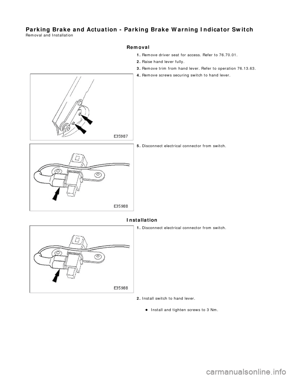
Parking Brake and Ac
tuat
ion - Parking Brake Warn ing Indicator Switch
Re
moval and Installation
Remov
al
Installation
1. R
emove driver seat for access. Refer to 76.70.01.
2. Raise hand lever fully.
3. Remove trim from hand lever. Refer to operation 76.13.63.
4. R
emove screws securing
switch to hand lever.
5. Di
sconnect electrical connector from switch.
1. Di
sconnect electrical connector from switch.
2. Install switch to hand lever.
пЃ¬Install and tigh
ten
screws to 3 Nm.
Page 417 of 2490
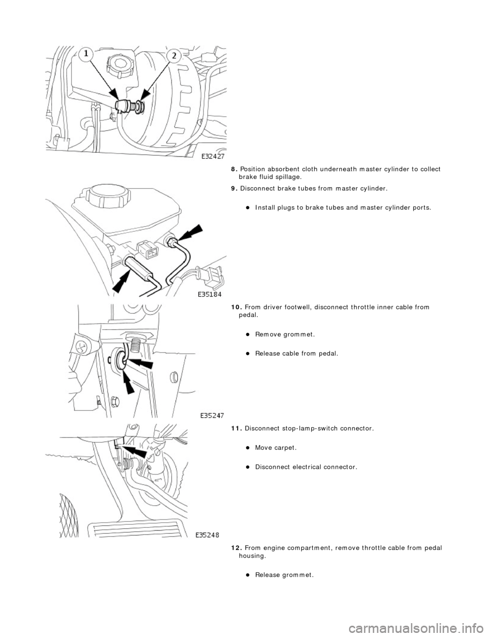
8. Posi
tion absorbent cloth underneath master cylinder to collect
brake fluid spillage.
9. Di
sconnect brake tubes from master cylinder.
пЃ¬Install plugs to brake tu
bes an
d master cylinder ports.
10
.
From driver footwell, disconne ct throttle inner cable from
pedal.
пЃ¬Re
move grommet.
пЃ¬Relea
se cable from pedal.
11
.
Disconnect stop-lamp-switch connector.
пЃ¬Move carpet.
пЃ¬Disc
onnect electrical connector.
12. From engine compartment, remo ve throttle cable from pedal
housing.
пЃ¬Re
lease grommet.
Page 431 of 2490
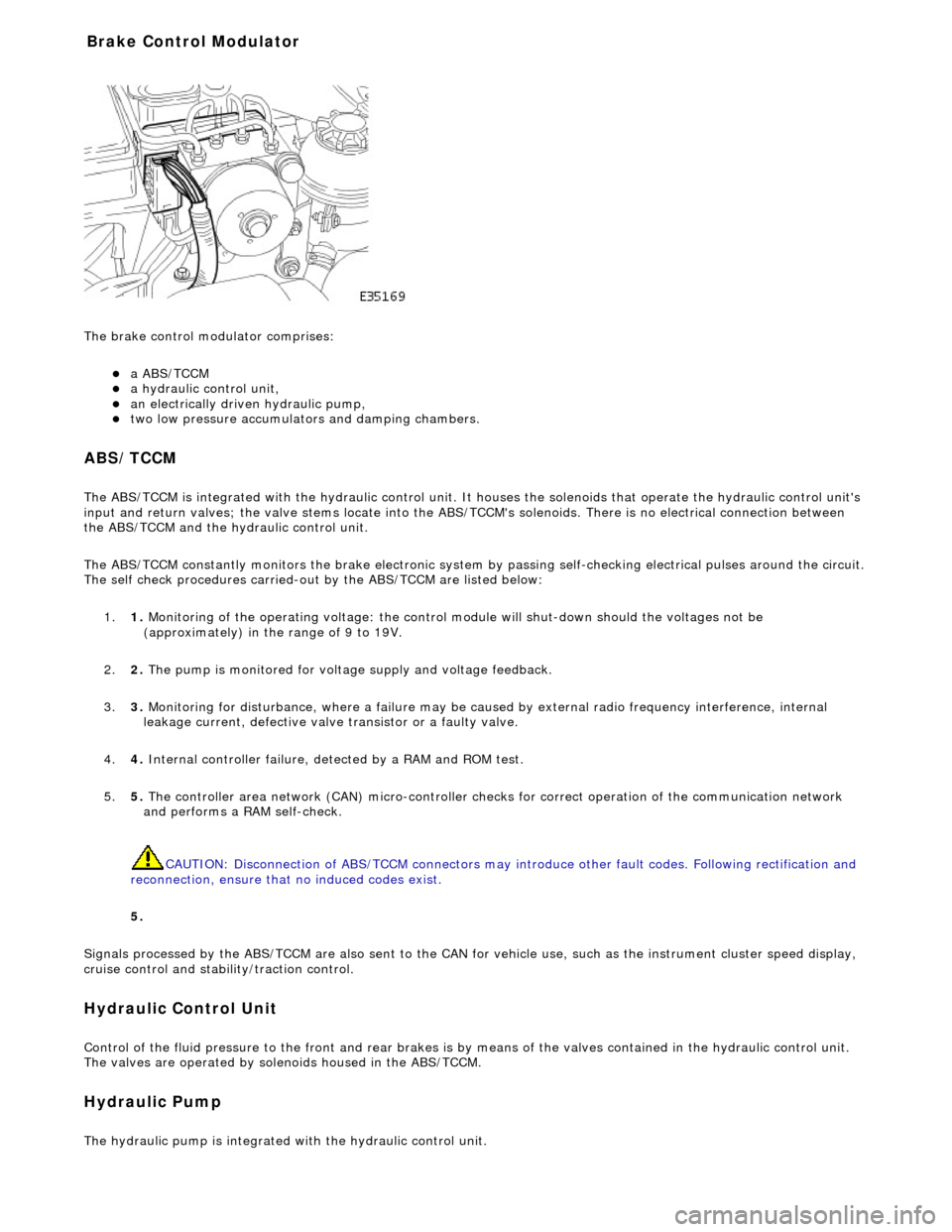
The brake
control modulator comprises:
пЃ¬a A
BS/TCCM
пЃ¬a h
ydraulic control unit,
пЃ¬an electrically driven hydrau
lic pump,
пЃ¬two low pressure accumulato
rs and damping chambers.
ABS/TCCM
The AB
S/TCCM is integrated with the hydrau
lic control unit. It houses the solenoids that operate the hydraulic control unit's
input and return valves; the valve stems locate into the ABS/TCCM's solenoids. There is no electrical connection between
the ABS/TCCM and the hydraulic control unit.
The ABS/TCCM constantly monitors the brake electronic system by passing self-checking electrical pulses around the circuit.
The self check procedures carried-out by the ABS/TCCM are listed below:
1. 1. Monitoring of the operating voltage: the control mo dule will shut-down should the voltages not be
(approximately) in the range of 9 to 19V.
2. 2. The pump is monitored for volt age supply and voltage feedback.
3. 3. Monitoring for disturbance, where a failure may be caus ed by external radio frequency interference, internal
leakage current, defective valve transistor or a faulty valve.
4. 4. Internal controller failure, de tected by a RAM and ROM test.
5. 5. The controller area network (CAN) micr o-controller checks for correct operation of the communication network
and performs a RAM self-check.
CAUTION: Disconnection of ABS/TCCM connectors may introduce other fault codes. Following rectification and
reconnection, ensure that no induced codes exist.
5.
Signals processed by the ABS/TCCM are also sent to the CAN for vehicle use, such as the instrument cluster speed display,
cruise control and stability/traction control.
Hydraulic Control Unit
Control of
the fluid pressure to
the front and rear brakes is by means of the valves contained in the hydraulic control unit.
The valves are operated by solenoids housed in the ABS/TCCM.
Hydraulic Pump
The
hydraulic pump is integrated
with the hydraulic control unit.
Bra
ke Control Modulator
Page 435 of 2490
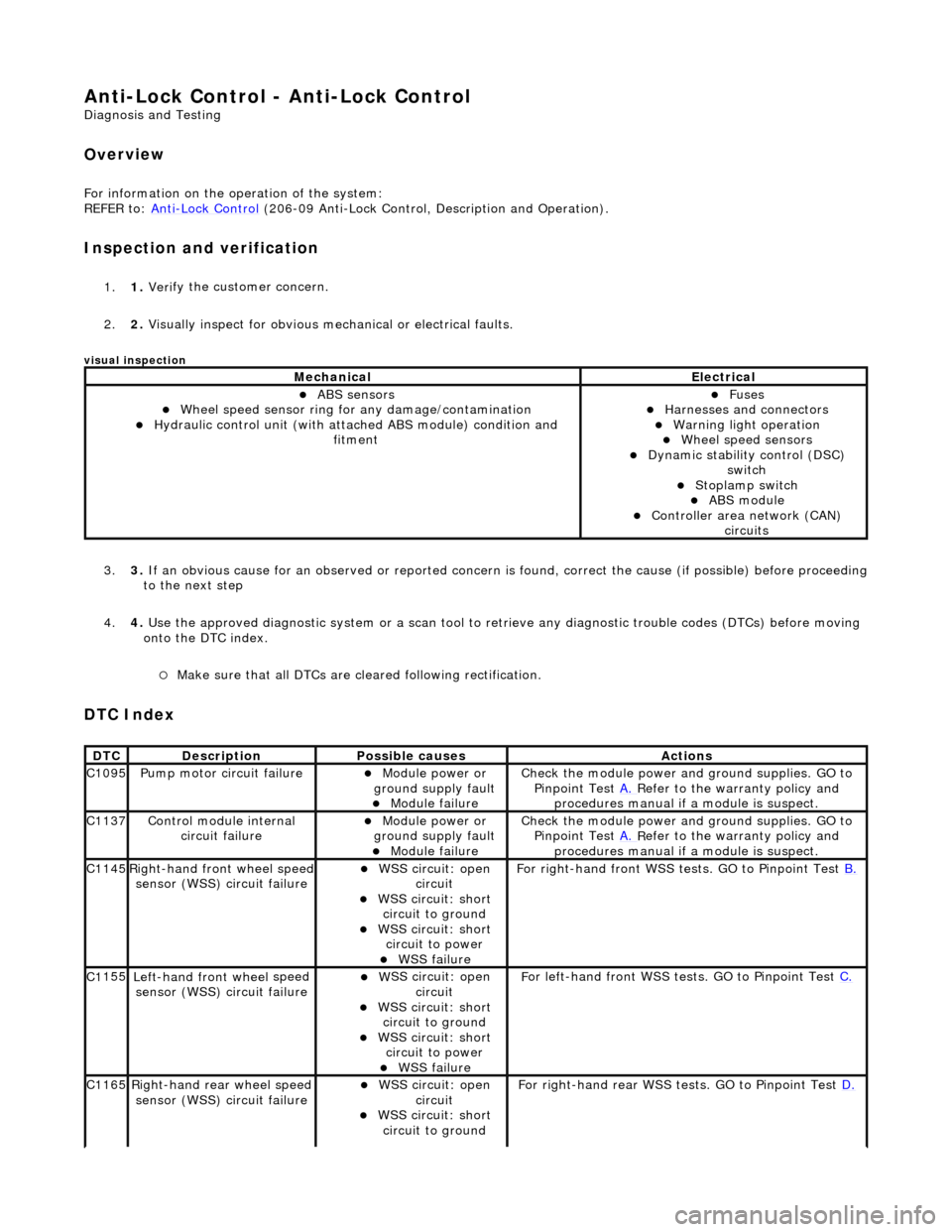
Anti-Lock Control - Anti-Lock Control
D
iagnosis and Testing
Ov
erview
Fo
r information on the operation of the system:
REFER to: Anti
-Lock Control
(206-09 Anti-Lock Control, Description and Operation).
I
nspection and verification
1.
1. Veri
fy the customer concern.
2. 2. Visually inspect for obvious mech anical or electrical faults.
visual insp
ection
3.
3. If
an obvious cause for an observed or
reported concern is found, correct th e cause (if possible) before proceeding
to the next step
4. 4. Use the approved diagnostic system or a scan tool to retrieve any diagnostic trouble codes (DTCs) before moving
onto the DTC index.
п‚ЎMake sure that
all DTCs are cleared following rectification.
DTC Index
MechanicalElectrical
пЃ¬ABS se
nsors
пЃ¬W
heel speed sensor ring for
any damage/contamination
пЃ¬Hydrauli
c control unit (with attached ABS module) condition and
fitment
пЃ¬F
uses
пЃ¬Harnes
ses and connectors
пЃ¬War
ning light operation
пЃ¬Wh
eel speed sensors
пЃ¬Dynam
ic stability control (DSC)
switch
пЃ¬Stoplamp switch
пЃ¬ABS module пЃ¬Con
troller area network (CAN)
circuits
DT
C
De
scription
Possib
le causes
Acti
ons
C1
095
Pump mo
tor circuit failure
пЃ¬Module power or
gr
ound supply fault
пЃ¬Module
failure
Check the modu
le power and
ground supplies. GO to
Pinpoint Test A.
R
efer to the warranty policy and
procedures manual if a module is suspect.
C1
137
Control modu
le internal
circuit failure
пЃ¬Module power or
gr
ound supply fault
пЃ¬Module
failure
Check the modu
le power and
ground supplies. GO to
Pinpoint Test A.
R
efer to the warranty policy and
procedures manual if a module is suspect.
C1
145
Right
-hand front wheel speed
sensor (WSS) circuit failure
пЃ¬W
SS circuit: open
circuit
пЃ¬W
SS circuit: short
circuit to ground
пЃ¬W
SS circuit: short
circuit to power
пЃ¬WSS
failure
F
or right-hand front WSS tests. GO to Pinpoint Test
B.
C1
155
Left-hand front wheel
speed
sensor (WSS) circuit failure
пЃ¬W
SS circuit: open
circuit
пЃ¬W
SS circuit: short
circuit to ground
пЃ¬W
SS circuit: short
circuit to power
пЃ¬WSS
failure
F
or left-hand front WSS tests. GO to Pinpoint Test
C.
C1
165
Ri
ght-hand rear wheel speed
sensor (WSS) circuit failure
пЃ¬W
SS circuit: open
circuit
пЃ¬W
SS circuit: short
circuit to ground
F
or right-hand rear WSS test
s. GO to Pinpoint Test D.
Page 436 of 2490
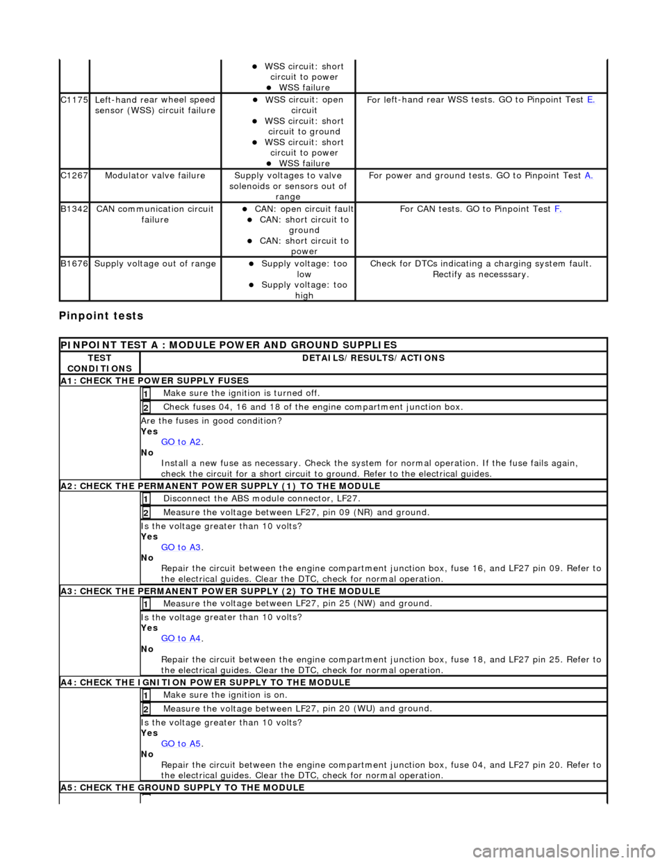
Pinpoint tests
пЃ¬W
S
S circuit: short
circuit to power
пЃ¬WSS f
ailure
C1
175Left -hand re
ar wheel speed
sensor (WSS) circuit failure
пЃ¬W S
S circuit: open
circuit
пЃ¬WS
S circuit: short
circuit to ground
пЃ¬W S
S circuit: short
circuit to power
пЃ¬WSS f
ailure
F
or l
eft-hand rear WSS test
s. GO to Pinpoint Test E.
C1267Modulat or valv
e failure
Supply volt
ages
to valve
solenoids or sensors out of range
Fo
r power and ground tests. GO to Pinpoint Test
A.
B1342CAN co
mmunication circuit
failure
пЃ¬CAN :
open circuit fault
пЃ¬CAN:
short circuit to
ground
пЃ¬CAN :
short circuit to
power
Fo
r CAN tests. GO to Pinpoint Test
F.
B1676Supply volt
age out of range
пЃ¬Supply voltage:
too
low
пЃ¬Supply volt age:
too
high
Check fo
r DTCs indicating a charging system fault.
Rectify as necesssary.
PI
NPOINT TEST A : MODULE
POWER AND GROUND SUPPLIES
TES
T
CONDITIONS
D E
TAILS/RESULTS/ACTIONS
A
1
: CHECK THE POWER SUPPLY FUSES
Make sure the igniti
on is turned off. 1
Chec
k fuses 04, 16 and 18 of the engine compartment junction box.
2
Are th
e fus
es in good condition?
Yes GO to A2
.
No
Install a new f
use as
necessary. Check the syst em for normal operation. If the fuse fails again,
check the circuit for a short circuit to ground. Refer to the electrical guides.
A2: CHECK THE PERMANENT
POWER SUPPLY (1) TO THE MODULE
Disc
onnect the ABS module connector, LF27.
1
Measure the voltage between LF
2
7, pin 09 (NR) and ground.
2
Is the vol
t
age greater than 10 volts?
Yes GO to A3
.
No Re
pair the circuit between the engine compartment
junction box, fuse 16, and LF27 pin 09. Refer to
the electrical guides. Clear the DTC, check for normal operation.
A3: CHECK THE PERMANENT
POWER SUPPLY (2) TO THE MODULE
Meas
ure t
he voltage between LF27, pin 25 (NW) and ground.
1
Is the vol
t
age greater than 10 volts?
Yes GO to A4
.
No
Re
pair the circuit between the engine compartment ju
nction box, fuse 18, and LF27 pin 25. Refer to
the electrical guides. Clear the DTC, check for normal operation.
A4: CHECK
THE IGNITION POWER SUPPLY TO THE MODULE
Make sure the ignition is on. 1
Measure the
voltage between LF 2
7, pin 20 (WU) and ground.
2
Is the vol
t
age greater than 10 volts?
Yes GO to A5
.
No Re
pair the circuit between the engine compartment ju
nction box, fuse 04, and LF27 pin 20. Refer to
the electrical guides. Clear the DTC, check for normal operation.
A5: CHECK
THE GROUND SUPPLY TO THE MODULE
Page 437 of 2490
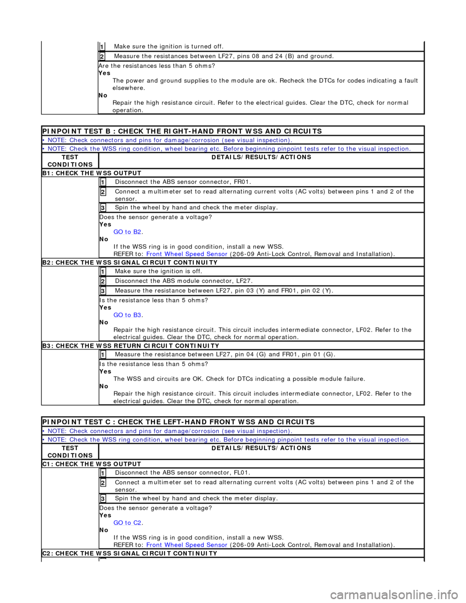
Make sure the ignition is turned off. 1
Meas
ure the resistances between LF27,
pins 08 and 24 (B) and ground.
2
Are
the resistances less than 5 ohms?
Yes The power and ground supplies to the module are ok . Recheck the DTCs for codes indicating a fault
elsewhere.
No Repair the high resistance circui t. Refer to the electrical guides. Clear the DTC, check for normal
operation.
PINPOINT TE
ST B : CHECK THE RIGHT-HAND FRONT WSS AND CIRCUITS
•
NOTE: Check connectors and pins for damage/corrosion
(see visual inspection).
•
NOTE: Check the WSS ring condition, whee
l bearing etc. Before beginning pinpoint test s refer to the visual inspection.
TE
ST
CONDITIONS
D
ETAILS/RESULTS/ACTIONS
B1: CHECK
THE WSS OUTPUT
Disc
onnect the ABS sensor connector, FR01.
1
Connec
t a multimeter set
to read alternating curr ent volts (AC volts) between pins 1 and 2 of the
sensor.
2
Spin
the wheel by hand and check the meter display.
3
Doe
s the sensor generate a voltage?
Yes GO to B2
.
No
If the WSS ring is in good condition, install a new WSS.
REFER to: Front Wheel Speed Sensor
(20
6-09 Anti-Lock Control, Removal and Installation).
B2:
CHECK THE WSS SIGNAL CIRCUIT CONTINUITY
Make sure the ignition is off. 1
Di
sconnect the ABS module connector, LF27.
2
Meas
ure the resistance between LF27
, pin 03 (Y) and FR01, pin 02 (Y).
3
I
s the resistance less than 5 ohms?
Yes GO to B3
.
No
Repair the high resistance circui t. This circuit includes intermediate connector, LF02. Refer to the
electrical guides. Clear the DTC, check for normal operation.
B3:
CHECK THE WSS RETURN CIRCUIT CONTINUITY
Meas
ure the resistance between LF27
, pin 04 (G) and FR01, pin 01 (G).
1
I
s the resistance less than 5 ohms?
Yes The WSS and circuits are OK. Check for DTCs indicating a possible module failure.
No Repair the high resistance circui t. This circuit includes intermediate connector, LF02. Refer to the
electrical guides. Clear the DTC, check for normal operation.
P
INPOINT TEST C : CHECK THE LEFT-HAND FRONT WSS AND CIRCUITS
•
NOTE: Check connectors and pins for damage/corrosion
(see visual inspection).
•
NOTE: Check the WSS ring condition, whee
l bearing etc. Before beginning pinpoint test s refer to the visual inspection.
TE
ST
CONDITIONS
D
ETAILS/RESULTS/ACTIONS
C1
: CHECK THE WSS OUTPUT
Disc
onnect the ABS sensor connector, FL01.
1
Connec
t a multimeter set
to read alternating curr ent volts (AC volts) between pins 1 and 2 of the
sensor.
2
Spin
the wheel by hand and check the meter display.
3
Doe
s the sensor generate a voltage?
Yes GO to C2
.
No
If the WSS ring is in good condition, install a new WSS.
REFER to: Front Wheel Speed Sensor
(20
6-09 Anti-Lock Control, Removal and Installation).
C2
: CHECK THE WSS SIGNAL CIRCUIT CONTINUITY