electrical JAGUAR X308 1998 2.G Repair Manual
[x] Cancel search | Manufacturer: JAGUAR, Model Year: 1998, Model line: X308, Model: JAGUAR X308 1998 2.GPages: 2490, PDF Size: 69.81 MB
Page 461 of 2490
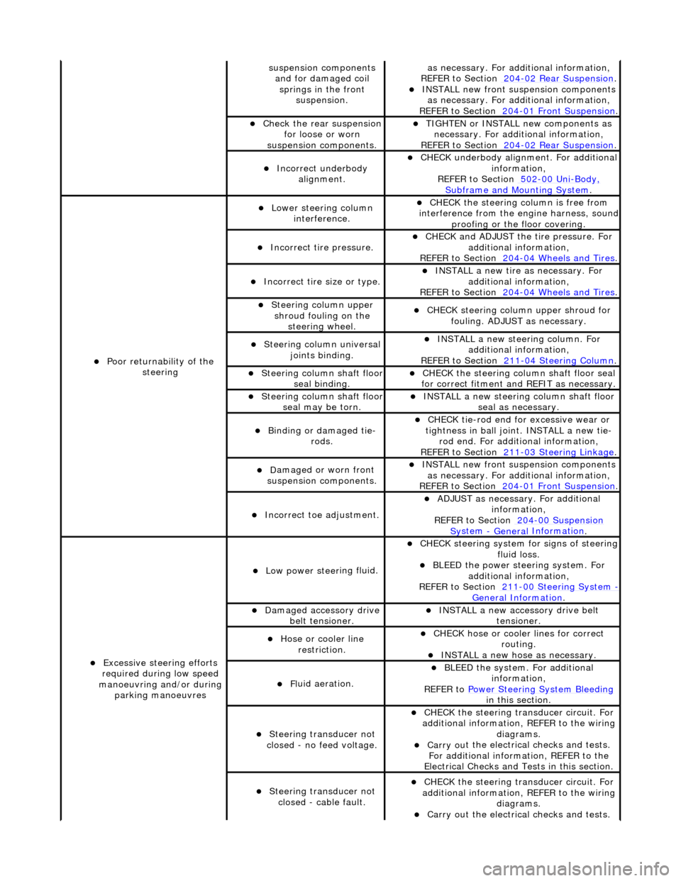
sus
pension components
and for damaged coil springs in the front suspension.
as necessary. For addi tional information,
REF
ER to Section 204
-0
2 Rear Suspension
. пЃ¬I
NSTALL new front suspension components
as necessary. For addi tional information,
REFER to Section 204
-01
Front Suspension
.
пЃ¬Chec
k the rear suspension
for loose or worn
suspension components.
пЃ¬TIGHTE
N or INSTALL new components as
necessary. For additi onal information,
REFER to Section 204
-0
2 Rear Suspension
.
пЃ¬Incorre
ct underbody
alignment.
пЃ¬CHECK
underbody alignment. For additional
information,
REFER to Section 502
-00
Uni
-Body, Subframe and M
ounting System
.
пЃ¬Poor r
eturnability of the
steering
пЃ¬Lower steeri
ng column
interference.
пЃ¬CHECK
the steering co
lumn is free from
interference from the en gine harness, sound
proofing or the floor covering.
пЃ¬Incorrect
tire pressure.
пЃ¬CHECK
and ADJUST the tire pressure. For
additional information,
REFER to Section 204
-0
4 Wheels and Tires
.
пЃ¬Incorrect
tire size or type.
пЃ¬IN
STALL a new tire as necessary. For
additional information,
REFER to Section 204
-0
4 Wheels and Tires
.
пЃ¬Steeri
ng column upper
shroud fouling on the steering wheel.
пЃ¬CHECK
steering column upper shroud for
fouling. ADJUST as necessary.
пЃ¬Steeri
ng column universal
joints binding.
пЃ¬IN
STALL a new steering column. For
additional information,
REFER to Section 211
-0
4 Steering Column
.
пЃ¬Steeri
ng column shaft floor
seal binding.
пЃ¬CHE
CK the steering column shaft floor seal
for correct fitm ent and REFIT as necessary.
пЃ¬Steeri
ng column shaft floor
seal may be torn.
пЃ¬IN
STALL a new steering column shaft floor
seal as necessary.
пЃ¬Bin
ding or damaged tie-
rods.
пЃ¬CHECK
tie-rod end for excessive wear or
tightness in ball joint. INSTALL a new tie- rod end. For additional information,
REFER to Section 211
-0
3 Steering Linkage
.
пЃ¬D
amaged or worn front
suspension components.
пЃ¬I
NSTALL new front suspension components
as necessary. For addi tional information,
REFER to Section 204
-01
Front Suspension
.
пЃ¬Incorre
ct toe adjustment.
пЃ¬AD
JUST as necessary. For additional
information,
REFER to Section 204
-00
Suspension
Sy
stem
- General
Information
.
пЃ¬Excessive steeri
ng efforts
required during low speed
manoeuvring and/or during parking manoeuvres
пЃ¬Low power steer
ing fluid.
пЃ¬CHE
CK steering system
for signs of steering
fluid loss.
пЃ¬BLEE
D the power steering system. For
additional information,
REFER to Section 211
-0
0 Steering System
- General Informati
on
.
пЃ¬Damaged accessory driv
e
belt tensioner.
пЃ¬INST
ALL a new accessory drive belt
tensioner.
пЃ¬Hose or cooler li
ne
restriction.
пЃ¬CHECK
hose or cooler lines for correct
routing.
пЃ¬INST
ALL a new hose as necessary.
пЃ¬Fl
uid aeration.
пЃ¬BLEE
D the system. For additional
information,
REFER to Power Steering System Bleeding
in t
his section.
пЃ¬Steeri
ng transducer not
closed - no feed voltage.
пЃ¬CHECK
the steering transducer circuit. For
additional information, REFER to the wiring diagrams.
пЃ¬Carry ou
t the electrical checks and tests.
For additional information, REFER to the
Electrical Checks and Tests in this section.
пЃ¬Steeri
ng transducer not
closed - cable fault.
пЃ¬CHECK
the steering transducer circuit. For
additional information, REFER to the wiring diagrams.
пЃ¬Carry ou
t the electrical checks and tests.
Page 462 of 2490
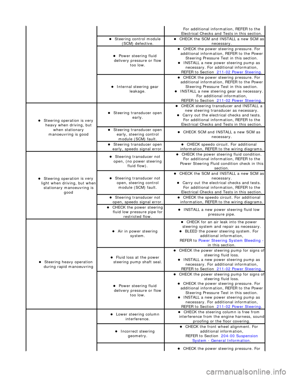
Fo
r additional information, REFER to the
Electrical Checks and Tests in this section.
пЃ¬Steering control
module
(SCM) defective.
пЃ¬CHECK
the SCM and INSTALL a new SCM as
necessary.
пЃ¬Power steeri ng f
luid
delivery pressure or flow too low.
пЃ¬CHECK
the power stee
ring pressure. For
additional information, REFER to the Power Steering Pressure Test in this section.
пЃ¬INSTALL a ne
w power steering pump as
necessary. For additi onal information,
REFER to Section 211
-0 2
Power Steering
.
пЃ¬Internal steering gear
leakage.
пЃ¬CHECK
the power stee
ring pressure. For
additional information, REFER to the Power Steering Pressure Test in this section.
пЃ¬INSTALL a ne
w steering
gear as necessary.
For additional information,
REFER to Section 211
-0 2
Power Steering
.
пЃ¬Steeri
ng operati
on is very
heavy when driving, but when stationary
manoeuvring is good
пЃ¬Steering transducer open earl
y.
пЃ¬CHECK
steering transducer and INSTALL a
new steering transducer as necessary.
пЃ¬Carry out th
e electrical checks and tests.
For additional information, REFER to the
Electrical Checks and Tests in this section.
пЃ¬Steering transducer open
early,
steering control
module (SCM) fault.
пЃ¬CHECK
SCM and INSTALL a new SCM as
necessary.
пЃ¬Steering transducer open
earl
y, speedo signal error.
пЃ¬CHECK
speedo
circui
t. For additional
information, REFER to the wiring diagrams.
пЃ¬Steeri ng operati
on is very
light when driving, but when
stationary manoeuvring is good
пЃ¬Steering transducer not
o
pen, (no power steering
fluid flow).
пЃ¬CHECK
the power steering fluid condition.
For additional information, REFER to the
Power Steering Fluid condition check in this section.
пЃ¬Steering transducer not o
pen, steering control
module (SCM) fault.
пЃ¬CHECK
the SCM and INSTALL a new SCM as
necessary.
пЃ¬Carry out th
e electrical checks and tests.
For additional information, REFER to the
Electrical Checks and Tests in this section.
пЃ¬Steering transducer not
o
pen, speedo signal error.
пЃ¬CHECK
the speedo circ
uit. For additional
information, REFER to the wiring diagrams.
пЃ¬CHECK
the power steering
fluid low pressure pipe for restricted flow.
пЃ¬INSTALL a ne
w power steering fluid low
pressure pipe.
пЃ¬S t
eering heavy operation
during rapid manoeuvring
пЃ¬Ai r i
n power steering
system.
пЃ¬CHECK for an air l
eak into the power
steering system and re pair as necessary.
пЃ¬BLEED the
power steering system. For
additional information,
REFER to Power Steering System Bleeding
- in t hi
s section.
пЃ¬Fluid loss at the power
steering pump shaft seal.
пЃ¬CHECK the power steer
ing pump for signs o
f steering fl
ui
d loss.
пЃ¬INST
ALL a ne
w power steering pump as
necessary. For additi onal information,
REFER to Section 211
-0 2
Power Steering
.
пЃ¬Power steeri
ng f
luid
delivery pressure or flow too low.
пЃ¬CHECK the power steer
ing pump for signs o
f steering fl
ui
d loss.
пЃ¬CHECK
the power stee
ring pressure. For
additional information, REFER to the Power Steering Pressure Test in this section.
пЃ¬INSTALL a ne
w power steering pump as
necessary. For additi onal information,
REFER to Section 211
-02
Power Steering
.
пЃ¬Lower steeri
ng col
umn
interference.
пЃ¬CHECK
the steering co
lumn is free from
interference from the en gine harness, sound
proofing or the floor covering.
пЃ¬Incorrect steering geometry. пЃ¬CHE
CK the front wheel alignment. For
additional information,
REFER to Section 204
-00 Sus
pension
Sy
ste
m
- General
Information
.
пЃ¬CHECK
the power stee
ring pressure. For
Page 463 of 2490
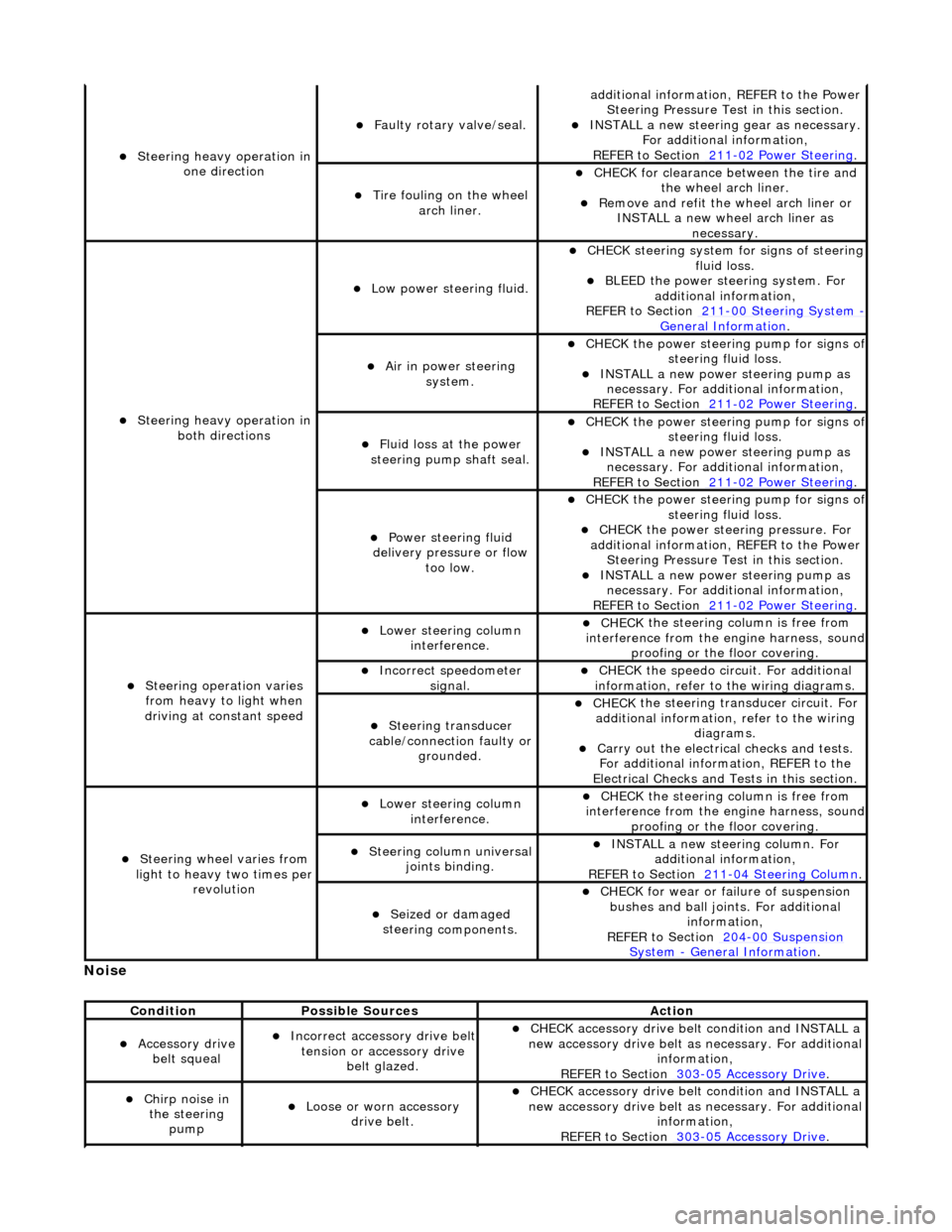
No
ise
пЃ¬S
teering heavy operation in
one direction
пЃ¬F
aulty rotary valve/seal.
addi
tional information, REFER to the Power
Steering Pressure Test in this section.
пЃ¬INST
ALL a new steering
gear as necessary.
For additional information,
REFER to Section 211
-0
2 Power Steering
.
пЃ¬Ti
re fouling on the wheel
arch liner.
пЃ¬CHECK for
clearance be
tween the tire and
the wheel arch liner.
пЃ¬R
emove and refit the wheel arch liner or
INSTALL a new wheel arch liner as necessary.
пЃ¬S
teering heavy operation in
both directions
пЃ¬Low power steer
ing fluid.
пЃ¬CHE
CK steering system
for signs of steering
fluid loss.
пЃ¬BLEE
D the power steering system. For
additional information,
REFER to Section 211
-0
0 Steering System
- General Informati
on
.
пЃ¬Ai
r in power steering
system.
пЃ¬CHECK
the power steering pump for signs o
f steering fl
uid loss.
пЃ¬INST
ALL a new power steering pump as
necessary. For additi onal information,
REFER to Section 211
-0
2 Power Steering
.
пЃ¬Fluid loss at the power
steering pump shaft seal.
пЃ¬CHECK
the power steering pump for signs o
f steering fl
uid loss.
пЃ¬INST
ALL a new power steering pump as
necessary. For additi onal information,
REFER to Section 211
-0
2 Power Steering
.
пЃ¬Power steeri
ng fluid
delivery pressure or flow too low.
пЃ¬CHECK
the power steering pump for signs o
f steering fl
uid loss.
пЃ¬CHECK
the power stee
ring pressure. For
additional information, REFER to the Power Steering Pressure Test in this section.
пЃ¬INST
ALL a new power steering pump as
necessary. For additi onal information,
REFER to Section 211
-0
2 Power Steering
.
пЃ¬Steeri
ng operation varies
from heavy to light when
driving at constant speed
пЃ¬Lower steeri
ng column
interference.
пЃ¬CHECK
the steering co
lumn is free from
interference from the en gine harness, sound
proofing or the floor covering.
пЃ¬Incorre
ct sp
eedometer
signal.
пЃ¬CHECK
the speedo circ
uit. For additional
information, refer to the wiring diagrams.
пЃ¬Steeri
ng transducer
cable/connection faulty or grounded.
пЃ¬CHECK
the steering transducer circuit. For
additional information, refer to the wiring diagrams.
пЃ¬Carry ou
t the electrical checks and tests.
For additional information, REFER to the
Electrical Checks and Tests in this section.
пЃ¬Steeri
ng wheel varies from
light to heavy two times per revolution
пЃ¬Lower steeri
ng column
interference.
пЃ¬CHECK
the steering co
lumn is free from
interference from the en gine harness, sound
proofing or the floor covering.
пЃ¬Steeri
ng column universal
joints binding.
пЃ¬IN
STALL a new steering column. For
additional information,
REFER to Section 211
-0
4 Steering Column
.
пЃ¬Seized or damaged
ste
ering components.
пЃ¬CHECK
for wear or failure of suspension
bushes and ball join ts. For additional
information,
REFER to Section 204
-00
Suspension
Sy
stem
- General
Information
.
Cond
ition
Possib
le Sources
Acti
on
пЃ¬Acce
ssory drive
belt squeal
пЃ¬Incorre
ct accessory drive belt
tension or accessory drive belt glazed.
пЃ¬CHECK
accessory drive belt condition and INSTALL a
new accessory drive belt as necessary. For additional
information,
REFER to Section 303
-0
5 Accessory Drive
.
пЃ¬Chir
p noise in
the steering pump
пЃ¬Loose or worn accessory dr
ive belt.
пЃ¬CHECK
accessory drive belt condition and INSTALL a
new accessory drive belt as necessary. For additional
information,
REFER to Section 303
-0
5 Accessory Drive
.
Page 491 of 2490
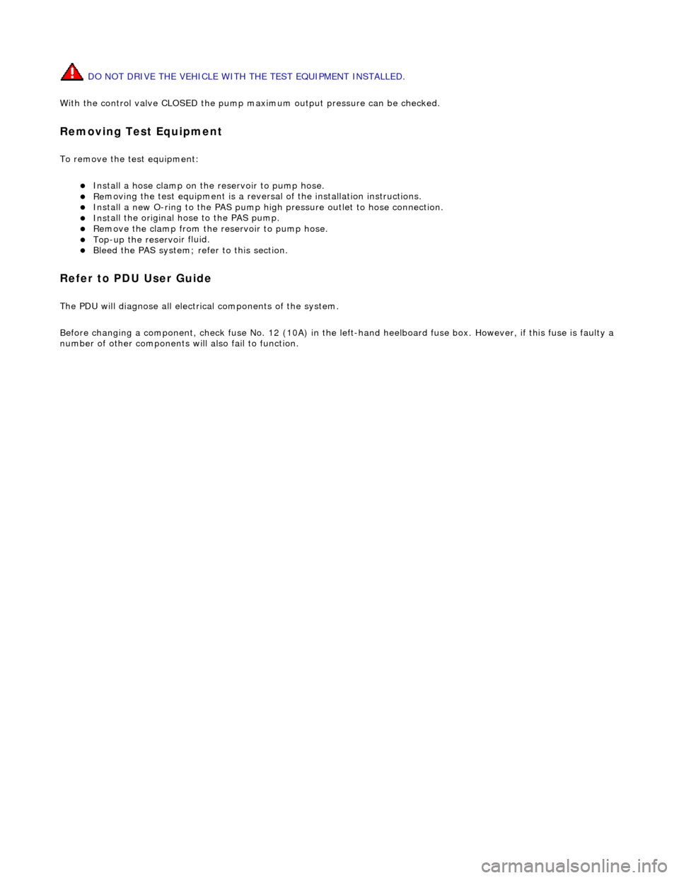
DO NOT DRIVE THE VEHICLE WITH THE TEST EQUIPMENT INSTALLED.
With the control valve CLOSED the pump maximum output pressure can be checked.
Remov
ing Test Equipment
T
o remove the test equipment:
пЃ¬Install a hose clamp
on the
reservoir to pump hose.
пЃ¬Re
moving the test equipmen
t is a reversal of the installation instructions.
пЃ¬Install a new O-r
ing to the PAS pump high
pressure outlet to hose connection.
пЃ¬Inst
all the original hose to the PAS pump.
пЃ¬R
emove the clamp from the reservoir to pump hose.
пЃ¬Top-up the reservoi
r fluid.
пЃ¬B
leed the PAS system; refe
r to this section.
Refer to PDU
User Guide
T
he PDU will diagnose all electrical components of the system.
Before changing a component, chec k fuse No. 12 (10A) in the left-hand heelboard fu se box. However, if this fuse is faulty a
number of other components wi ll also fail to function.
Page 493 of 2490

Righ
t-hand drive vehicles
All vehicles
7. De
tach the steering
column lower shaft.
1. Loosen the steering column lower shaft retaining bolt.
2. Remove and discard the st eering column lower shaft
retaining bolt.
3. Detach the steering column lower shaft.
8. Di
sconnect the steering gear transducer electrical connector.
9. Cut an
d discard the stee
ring gear transducer harness tie-strap.
10
.
Cut and discard the power steeri ng return pipe tie-strap.
11. Detach the power steering re turn pipe from the mounting
rubber.
Page 496 of 2490

Right
-hand drive vehicles
All vehicles
only
).
8. Install a new power st ee
ring return
pipe tie-strap.
9. Install a new steering gear transducer harness tie-strap.
10 . Conne
ct the steering gear transducer electrical connector.
пЃ¬On righ
t-hand drive vehicles
, position the steering gear
transducer harness behind th e power steering return pipe.
11
. NOTE
: Right-hand shown, left-hand similar.
Attach the tie rod end.
Page 708 of 2490
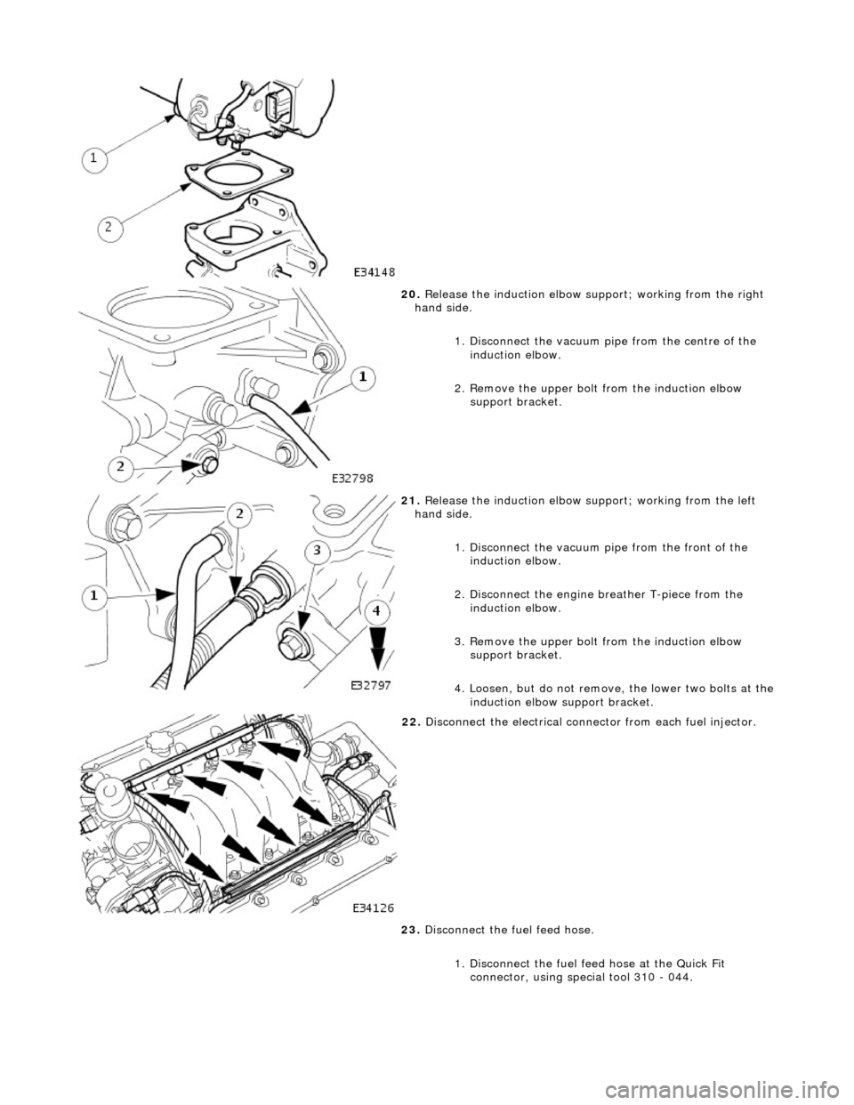
20. Release the induction elbow su pport; working from the right
hand side.
1. Disconnect the vacuum pi pe from the centre of the
induction elbow.
2. Remove the upper bolt from the induction elbow support bracket.
21. Release the induction elbow su pport; working from the left
hand side.
1. Disconnect the vacuum pipe from the front of the
induction elbow.
2. Disconnect the engine breather T-piece from the induction elbow.
3. Remove the upper bolt from the induction elbow support bracket.
4. Loosen, but do not remove , the lower two bolts at the
induction elbow support bracket.
22. Disconnect the electrical conne ctor from each fuel injector.
23. Disconnect the fuel feed hose.
1. Disconnect the fuel f eed hose at the Quick Fit
connector, using special tool 310 - 044.
Page 714 of 2490
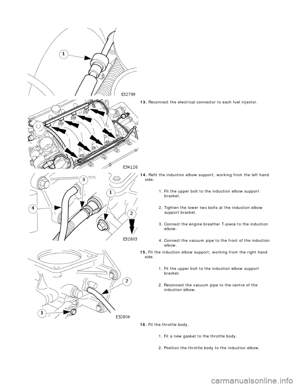
13. Reconnect the electrical connector to each fuel injector.
14. Refit the induction elbow support ; working from the left hand
side.
1. Fit the upper bolt to the induction elbow support
bracket.
2. Tighten the lower two bolts at the induction elbow support bracket.
3. Connect the engine breather T-piece to the induction elbow.
4. Connect the vacuum pipe to the front of the induction
elbow.
15. Fit the induction elbow support; working from the right hand
side.
1. Fit the upper bolt to the induction elbow support
bracket.
2. Reconnect the vacuum pi pe to the centre of the
induction elbow.
16. Fit the throttle body.
1. Fit a new gasket to the throttle body.
2. Position the throttle body to the induction elbow.
Page 722 of 2490
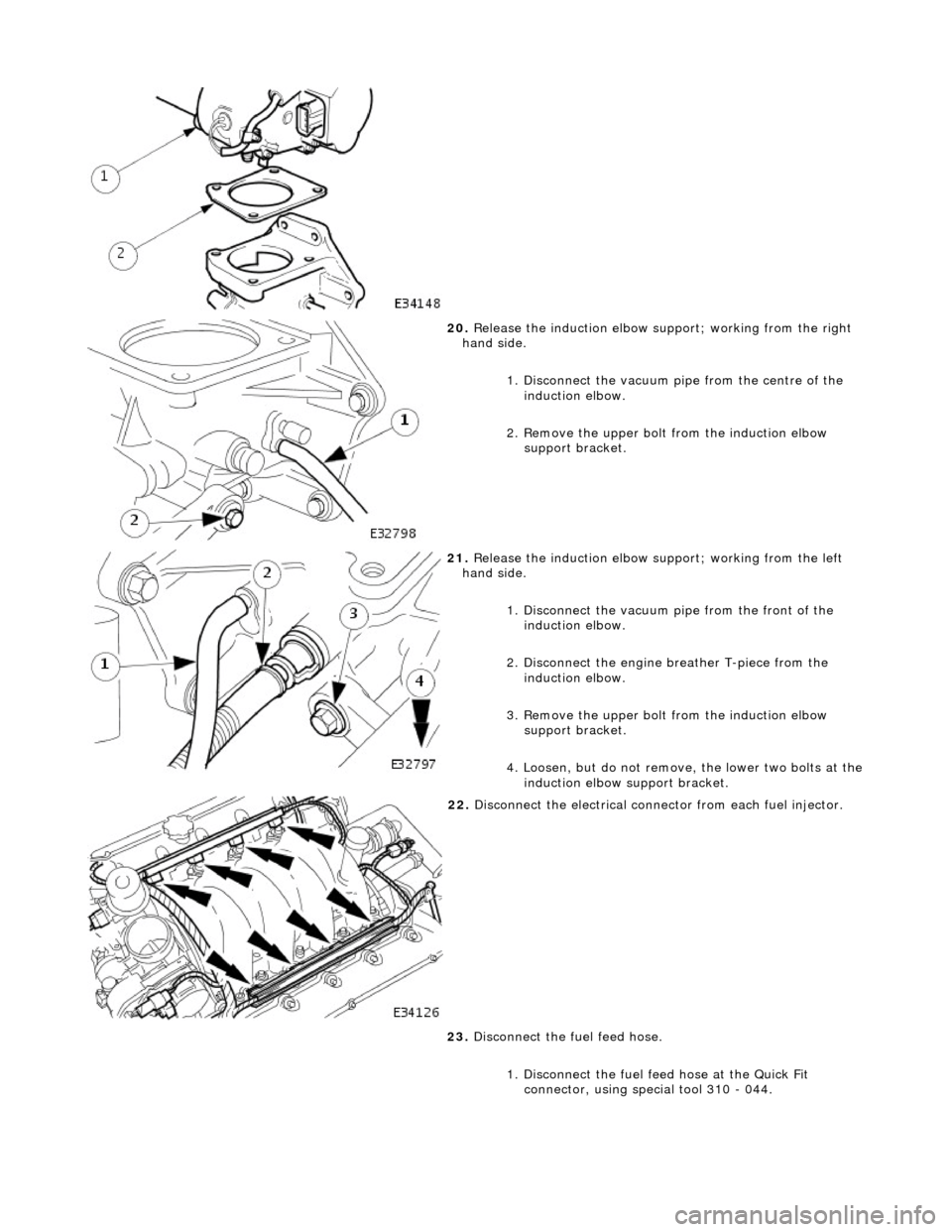
20. Release the induction elbow su pport; working from the right
hand side.
1. Disconnect the vacuum pi pe from the centre of the
induction elbow.
2. Remove the upper bolt from the induction elbow support bracket.
21. Release the induction elbow su pport; working from the left
hand side.
1. Disconnect the vacuum pipe from the front of the
induction elbow.
2. Disconnect the engine breather T-piece from the induction elbow.
3. Remove the upper bolt from the induction elbow support bracket.
4. Loosen, but do not remove , the lower two bolts at the
induction elbow support bracket.
22. Disconnect the electrical conne ctor from each fuel injector.
23. Disconnect the fuel feed hose.
1. Disconnect the fuel f eed hose at the Quick Fit
connector, using special tool 310 - 044.
Page 724 of 2490
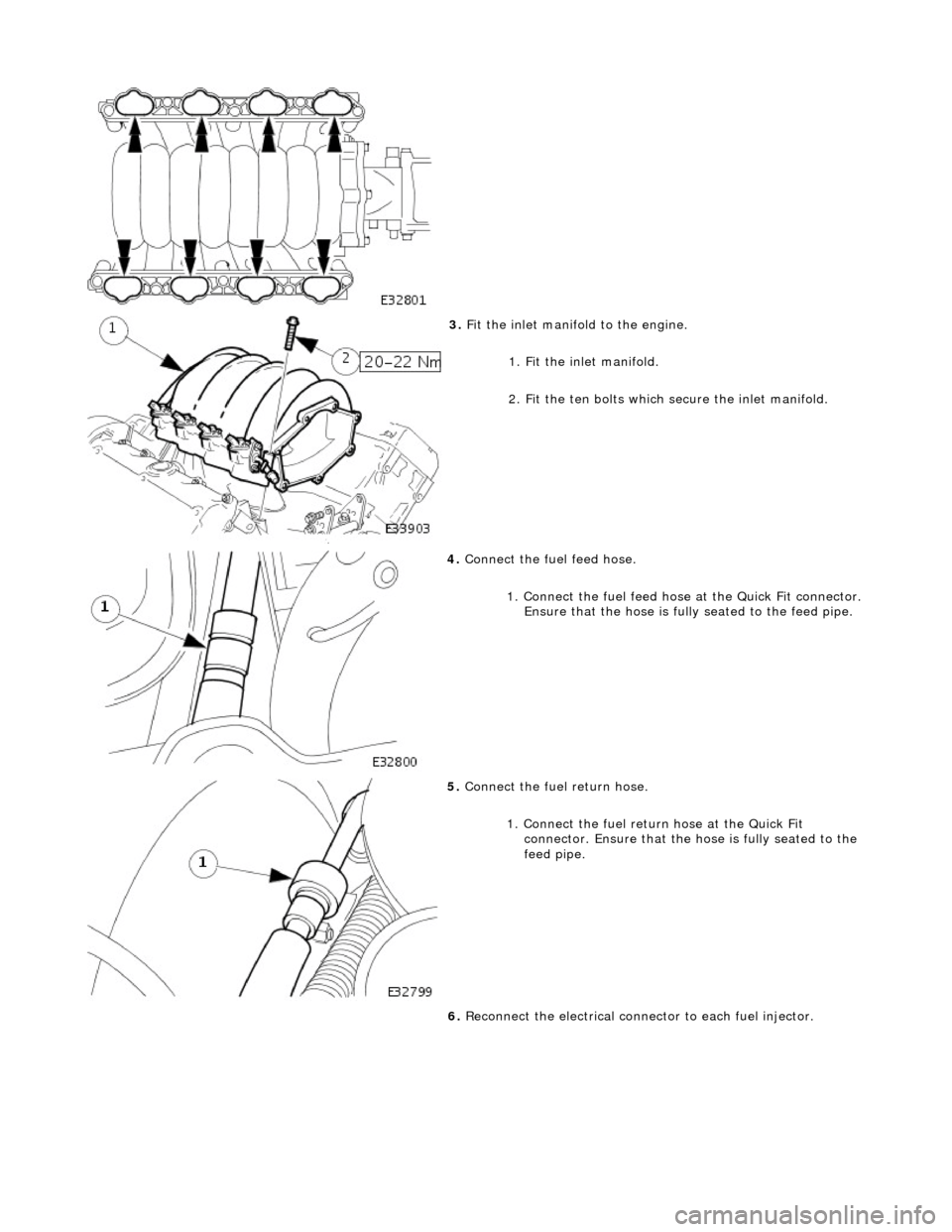
3. Fit the inlet manifold to the engine.
1. Fit the inlet manifold.
2. Fit the ten bolts which secure the inlet manifold.
4. Connect the fuel feed hose.
1. Connect the fuel feed hose at the Quick Fit connector. Ensure that the hose is fully seated to the feed pipe.
5. Connect the fuel return hose.
1. Connect the fuel return hose at the Quick Fit
connector. Ensure th at the hose is fully seated to the
feed pipe.
6. Reconnect the electrical connector to each fuel injector.