fuse box JAGUAR X308 1998 2.G Repair Manual
[x] Cancel search | Manufacturer: JAGUAR, Model Year: 1998, Model line: X308, Model: JAGUAR X308 1998 2.GPages: 2490, PDF Size: 69.81 MB
Page 1985 of 2490
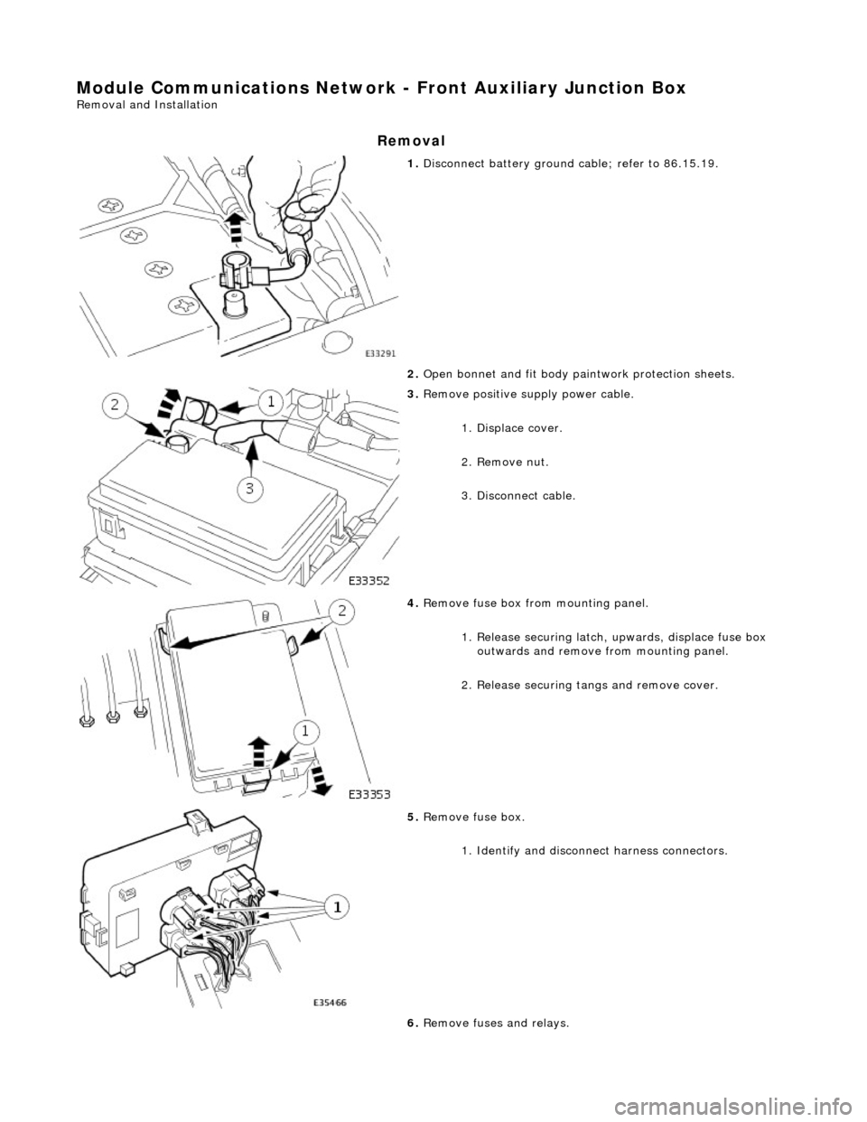
Module Communications Network - Front Auxiliary Junction Box
Removal and Installation
Removal
1. Disconnect battery ground cable; refer to 86.15.19.
2. Open bonnet and fit body pa intwork protection sheets.
3. Remove positive supply power cable.
1. Displace cover.
2. Remove nut.
3. Disconnect cable.
4. Remove fuse box fro m mounting panel.
1. Release securing latch, upwards, displace fuse box
outwards and remove from mounting panel.
2. Release securing tangs and remove cover.
5. Remove fuse box.
1. Identify and disconne ct harness connectors.
6. Remove fuses and relays.
Page 1986 of 2490

Installation
1. Note position of each relay and remove them.
2. Identify each fu
se and remove them.
The value and position of each fuse is illustrated on the lid
of the trunk compartment fuse box - for all fuse boxes on
the vehicle.
1. Installation is reverse of removal.
2. Reconnect battery ground cable; refer to 86.15.15.
Page 1987 of 2490
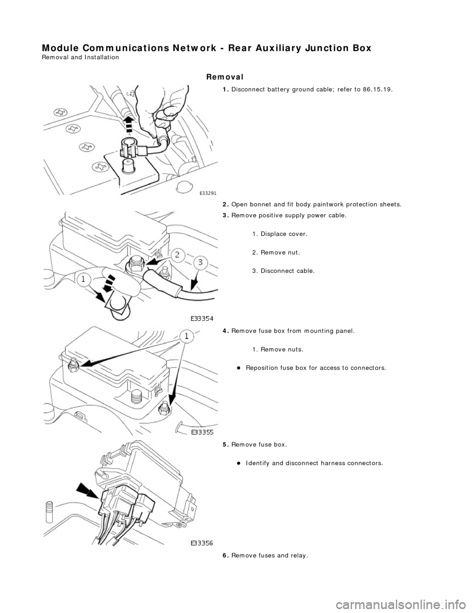
Module Communications Network - Rear Auxiliary Junction Box
Removal and Installation
Removal
1. Disconnect battery ground cable; refer to 86.15.19.
2. Open bonnet and fit body pa intwork protection sheets.
3. Remove positive supply power cable.
1. Displace cover.
2. Remove nut.
3. Disconnect cable.
4. Remove fuse box fro m mounting panel.
1. Remove nuts.
Reposition fuse box for access to connectors.
5. Remove fuse box.
Identify and disconnect harness connectors.
6. Remove fuses and relay.
Page 1988 of 2490

Installation
1. Release securing tangs and remove cover.
2. Remove relay.
3. Identify each fuse and remove them.
The value and position of each fuse is illustrated on the lid
of the trunk compartment fuse box - for all fuse boxes on
the vehicle.
1. Installation is reverse of removal.
2. Reconnect battery ground cable; refer to 86.15.15.
Page 2264 of 2490
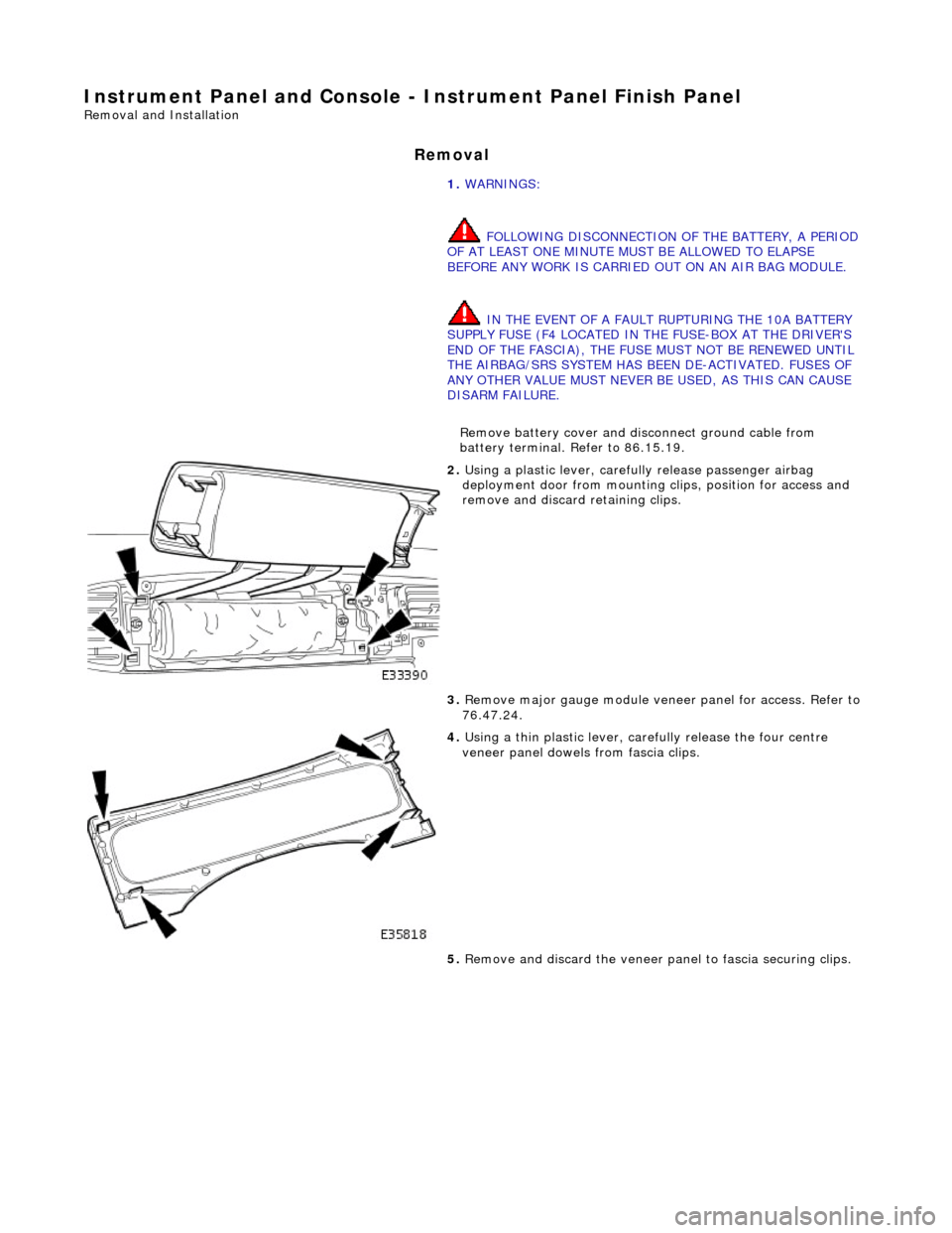
Instrument Panel and Console - Instrument Panel Finish Panel
Removal and Installation
Removal
1. WARNINGS:
FOLLOWING DISCONNECTION OF THE BATTERY, A PERIOD
OF AT LEAST ONE MINUTE MUST BE ALLOWED TO ELAPSE
BEFORE ANY WORK IS CARRIED OUT ON AN AIR BAG MODULE.
IN THE EVENT OF A FAULT RUPTURING THE 10A BATTERY
SUPPLY FUSE (F4 LOCATED IN THE FUSE-BOX AT THE DRIVER'S
END OF THE FASCIA), THE FUSE MUST NOT BE RENEWED UNTIL
THE AIRBAG/SRS SYSTEM HAS BEEN DE-ACTIVATED. FUSES OF
ANY OTHER VALUE MUST NEVER BE USED, AS THIS CAN CAUSE
DISARM FAILURE.
Remove battery cover and disconnect ground cable from
battery terminal. Refer to 86.15.19.
2. Using a plastic lever, carefu lly release passenger airbag
deployment door from mounting cl ips, position for access and
remove and discard retaining clips.
3. Remove major gauge module veneer panel for access. Refer to
76.47.24.
4. Using a thin plastic lever, care fully release the four centre
veneer panel dowels from fascia clips.
5. Remove and discard the veneer pa nel to fascia securing clips.
Page 2322 of 2490
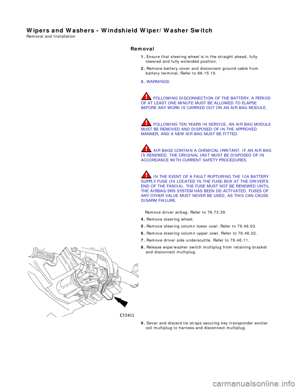
Wipers and Washers - Windshield Wiper/Washer Switch
Removal and Installation
Removal
1. Ensure that steering wheel is in the straight ahead, fully
lowered and fully ex tended position.
2. Remove battery cover and disc onnect ground cable from
battery terminal. Refer to 86.15.19.
3. WARNINGS:
FOLLOWING DISCONNECTION OF THE BATTERY, A PERIOD
OF AT LEAST ONE MINUTE MUST BE ALLOWED TO ELAPSE
BEFORE ANY WORK IS CARRIED OUT ON AN AIR BAG MODULE.
FOLLOWING TEN YEARS IN SERVICE, AN AIR BAG MODULE
MUST BE REMOVED AND DISPOSED OF IN THE APPROVED
MANNER, AND A NEW AIR BAG MUST BE FITTED.
AIR BAGS CONTAIN A CHEMICAL IRRITANT. IF AN AIR BAG
IS RENEWED, THE ORIGINAL UNIT MUST BE DISPOSED OF IN
ACCORDANCE WITH CURRENT SAFETY PROCEDURES.
IN THE EVENT OF A FAULT RUPTURING THE 10A BATTERY
SUPPLY FUSE (F4 LOCATED IN THE FUSE-BOX AT THE DRIVER'S
END OF THE FASCIA), THE FUSE MUST NOT BE RENEWED UNTIL
THE AIRBAG/SRS SYSTEM HAS BEEN DE-ACTIVATED. FUSES OF
ANY OTHER VALUE MUST NEVER BE USED, AS THIS CAN CAUSE
DISARM FAILURE.
Remove driver airbag. Refer to 76.73.39.
4. Remove steeri ng wheel.
5. Remove steering column lowe r cowl. Refer to 76.46.03.
6. Remove steering column upper cowl. Refer to 76.46.02.
7. Remove driver side unders cuttle. Refer to 76.46.11.
8. Release wipe/washer switch mult iplug from retaining bracket
and disconnect multiplug.
9. Sever and discard tie straps se curing key transponder exciter
coil multiplug to harness and disconnect multiplug.
Page 2372 of 2490
Supplemental Restraint System - Driver Air Bag Module
Removal and Installation
Removal
• WARNINGS:
FOLLOWING DISCONNECTION OF THE BATTERY, A PERIOD OF AT LEAST ONE MINUTE MUST BE ALLOWED TO ELAPSE
BEFORE ANY WORK IS CARRIED OUT ON AN AIR BAG MODULE.
FOLLOWING TEN YEARS IN SERVICE, AN AIR BAG MO DULE MUST BE REMOVED AND DISPOSED OF IN THE
APPROVED MANNER, AND A NEW AIR BAG MUST BE FITTED.
AIR BAGS CONTAIN A CHEMICAL IRRITANT. IF AN AIR BAG IS RENEWED, THE ORIGINAL UNIT MUST BE DISPOSED
OF IN ACCORDANCE WITH CURRENT SAFETY PROCEDURES.
IN THE EVENT OF A FAULT RUPTURING THE 10A BATTERY SUPPLY FUSE (F4 LOCATED IN THE FUSE-BOX AT THE
DRIVER'S END OF THE FASCIA), THE FUSE MUST NOT BE RENEWED UNTIL THE AIRBAG/SRS SYSTEM HAS BEEN DE-
ACTIVATED. FUSES OF ANY OTHER VALUE MUST NEVER BE USED, AS THIS CAN CAUSE DISARM FAILURE.
Installation
1. Remove battery cover and disc onnect ground cable from
battery terminal. Refer to 86.15.19.
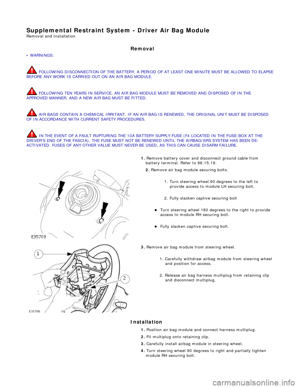
2. Remove air bag module securing bolts.
1. Turn steering wheel 90 degrees to the left to
provide access to module LH securing bolt.
2. Fully slacken captive securing bolt
Turn steering whee l 180 degrees to the right to provide
access to module RH securing bolt.
Fully slacken captive securing bolt.
3. Remove air bag module from steering wheel.
1. Carefully withdraw airbag module from steering wheel
and position for access.
2. Release air bag harness mu ltiplug from retaining clip
and disconnect multiplug.
1. Position air bag module and connect harness multiplug.
2. Fit multiplug onto retaining clip.
3. Carefully install airbag mo dule in steering wheel.
4. Turn steering wheel 90 degrees to right an d partially tighten
module RH securing bolt.
Page 2374 of 2490
Supplemental Restraint System - Passenger Air Bag Module
Removal and Installation
Removal
• WARNINGS:
FOLLOWING DISCONNECTION OF THE BATTERY, A PERIOD OF AT LEAST ONE MINUTE MUST BE ALLOWED TO ELAPSE
BEFORE ANY WORK IS CARRIED OUT ON AN AIR BAG MODULE.
FOLLOWING TEN YEARS IN SERVICE, AN AIR BAG MO DULE MUST BE REMOVED AND DISPOSED OF IN THE
APPROVED MANNER, AND A NEW AIR BAG MUST BE FITTED.
AIR BAGS CONTAIN A CHEMICAL IRRITANT. IF AN AIR BAG IS RENEWED, THE ORIGINAL UNIT MUST BE DISPOSED
OF IN ACCORDANCE WITH CURRENT SAFETY PROCEDURES.
IN THE EVENT OF A FAULT RUPTURING THE 10A BATTERY SUPPLY FUSE (F4 LOCATED IN THE FUSE-BOX AT THE
DRIVER'S END OF THE FASCIA), THE FUSE MUST NOT BE RENEWED UNTIL THE AIRBAG/SRS SYSTEM HAS BEEN DE-
ACTIVATED. FUSES OF ANY OTHER VALUE MUST NEVER BE USED, AS THIS CAN CAUSE DISARM FAILURE.
1. Remove battery cover and disc onnect ground cable from
terminal. Refer to 86.15.19.
2. Remove glove box. Refer to 76.52.03.
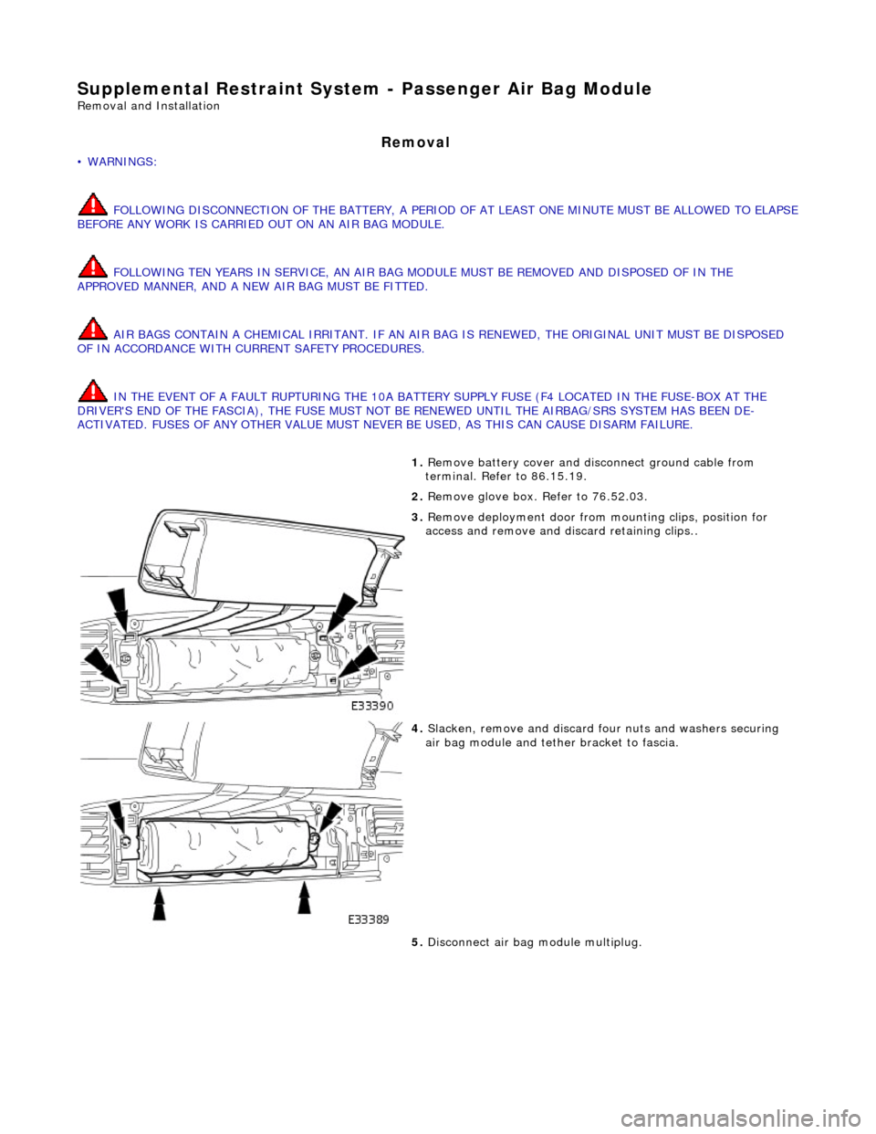
3. Remove deployment door from mounting clips, position for
access and remove and di scard retaining clips..
4. Slacken, remove and discard fo ur nuts and washers securing
air bag module and tether bracket to fascia.
5. Disconnect air bag module multiplug.
Page 2377 of 2490
Supplemental Restraint System - Side Air Bag Module
Removal and Installation
Removal
• WARNINGS:
A SIDE AIR BAG MUST ONLY BE RENEWED IF A FAULT FLAG HAS OCCURRED. IN THE EVENT OF SIDE AIR BAG
DEPLOYMENT DUE TO SIDE IMPACT, THE COMPLETE SEAT MUST BE RENEWED.
FOLLOWING TEN YEARS IN SERVICE, AN AIR BAG MO DULE MUST BE REMOVED AND DISPOSED OF IN THE
APPROVED MANNER, AND A NEW AIR BAG MUST BE FITTED.
FOLLOWING DISCONNECTION OF THE BATTERY, A PERIOD OF AT LEAST FIFTEEN MINUTES MUST BE ALLOWED TO
ELAPSE BEFORE DISCONNECTING THE SINGLE-POINT SENSIN G (SPS) UNIT AND AN ELAPSE OF 2 MINUTES ALLOWED
BEFORE DISCONNECTING ANY OTHER SUPPLEMENTARY RESTRAINT SYSTEM COMPONENT.
AIR BAGS CONTAIN A CHEMICAL IRRITANT. IF AN AIR BAG IS RENEWED, THE DISCARDED UNIT MUST BE DISPOSED
OF IN ACCORDANCE WITH CURRENT SAFETY PROCEDURES.
IN THE EVENT OF A FAULT RUPTURING THE 10A BATTERY SUPPLY FUSE (F4 LOCATED IN THE FUSE-BOX AT THE
DRIVER'S END OF THE FASCIA), THE FUSE MUST NOT BE RENEWED UNTIL THE AIRBAG/SRS SYSTEM HAS BEEN DE-
ACTIVATED. FUSES OF ANY OTHER VALUE MUST NEVER BE USED, AS THIS CAN CAUSE DISARM FAILURE.
1. Remove battery cover and disc onnect ground cable from
battery terminal. Refer to 86.15.19.
2. Remove seat from vehi cle. Refer to 76.70.01.
3. Remove seat back fini sher. Refer to 76.70.09.
4. Partially remove squab cover and foam pad for access. Refer to
76.70.15
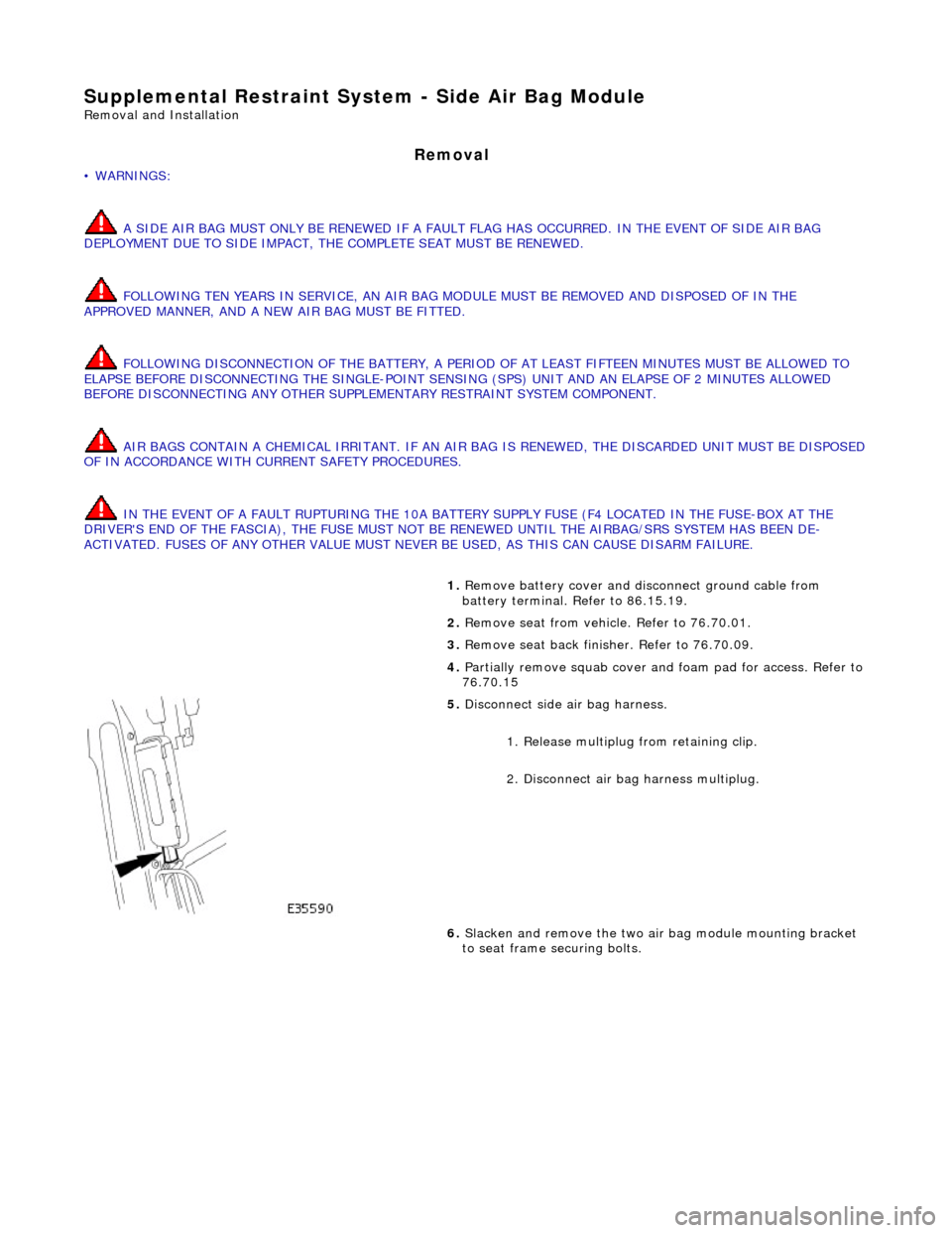
5. Disconnect side air bag harness.
1. Release multiplug from retaining clip.
2. Disconnect air ba g harness multiplug.
6. Slacken and remove the two air bag module mounting bracket
to seat frame securing bolts.
Page 2379 of 2490
Supplemental Restraint System - Side Impact Sensor
Removal and Installation
Removal
• WARNINGS:
FOLLOWING DISCONNECTION OF THE BA TTERY, A PERIOD OF AT LEAST FIFTEEN MINUTES MUST BE ALLOWED TO
ELAPSE BEFORE DISCONNECTING THE SINGLE-POINT SENSING (SPS) UNIT.
IN THE EVENT OF A FAULT RUPTURING THE 10A BATTER Y SUPPLY FUSE (F4 LOCATED IN THE FUSE-BOX AT THE
DRIVER'S END OF THE FASCIA), THE FUSE MUST NOT BE RENEWED UNTIL THE AIRBAG/SRS SYSTEM HAS BEEN DE-
ACTIVATED. FUSES OF ANY OTHER VALUE MUST NEVER BE USED, AS THIS CAN CAUSE DISARM FAILURE.
Installation
1. Remove battery cover and disconnect ground cable from battery
terminal. Refer to 86.15.19.
2. Remove'B' post trim pa d. Refer to 76.13.08.
3. Remove seat belt upper anchor and seat belt guide. Refer to
76.73.10
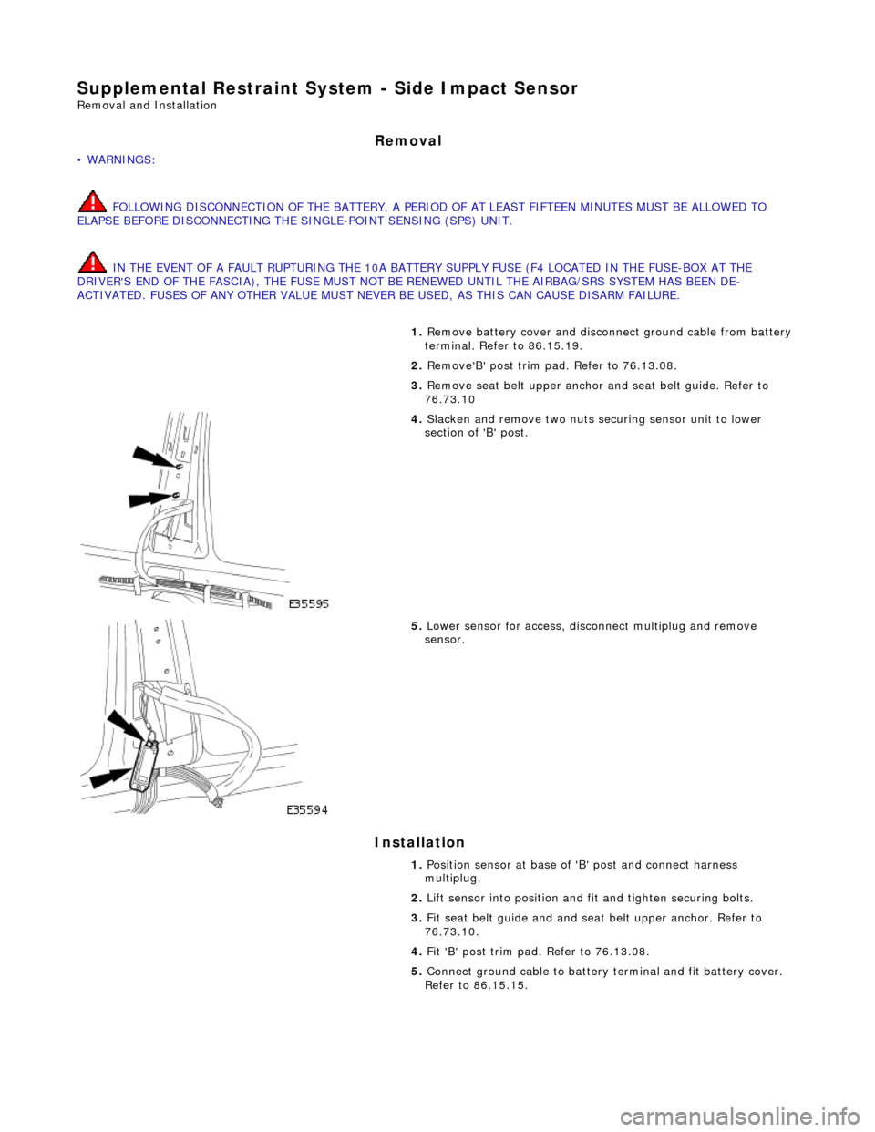
4. Slacken and remove two nuts securing sensor unit to lower
section of 'B' post.
5. Lower sensor for access, disco nnect multiplug and remove
sensor.
1. Position sensor at base of 'B' post and connect harness
multiplug.
2. Lift sensor into position and fit and tighten securing bolts.
3. Fit seat belt guide and and seat belt upper anchor. Refer to
76.73.10.
4. Fit 'B' post trim pad. Refer to 76.13.08.
5. Connect ground cable to battery terminal and fit battery cover.
Refer to 86.15.15.