lower JAGUAR X308 1998 2.G Repair Manual
[x] Cancel search | Manufacturer: JAGUAR, Model Year: 1998, Model line: X308, Model: JAGUAR X308 1998 2.GPages: 2490, PDF Size: 69.81 MB
Page 159 of 2490

Front Susp
ension - Wheel
Knuckle and Wheel Hub Assembly Conversion
Re
moval and Installation
Remov
al
S
pecial Tool(s)
R
oad spring compressor
204-111 (JD115)
Taper separator
211-098 (JD 100)
Front
suspension ball joint splitter
204-192 (JD 219)
Bal
l joint splitter
204-293
1. Raise front of vehicle and support on stands. Refer to Section
100-02.
2. Remove appropriate road wheel. Refer to 74.20.05.
3. Remove brake disc. Refer to 70.10.12.
4. Using wire or string, secure brak e caliper to road spring to take
weight off brake hose.
5. Raise vehicle sufficient to provide access for special tool 204-
111.
6. R
emove nut and bolt securing stabilizer bar link arm to lower
wishbone.
7. Remove nut securing link arm ba ll joint to stabilizer bar and
remove link arm from vehicle.
Page 160 of 2490

8. Inst
all special tool 204-111 in road spring.
Slacken tool
adjuster to suit spring length.
Fit adaptor and th
rust collar.
Positi
on stem of tool in center of spring passing dowel
through slot in su spension turret.
9. WA
RNING: WHEN TURNING TOOL ADJUSTER, ENSURE
THAT TOOL STEM DOES NOT ROTATE AND DISTURB POSITION
OF DOWEL IN SUSPENSION TURRET.
Engage dowel of special tool 204-111 in suspension turret and
rotate to position across slot.
10 . Lower veh
icle onto stands.
11 . R
otate tool adjuster to tension spring.
12. Remove wheel speed sensor se curing screw and withdraw
sensor from vertical link.
Page 162 of 2490
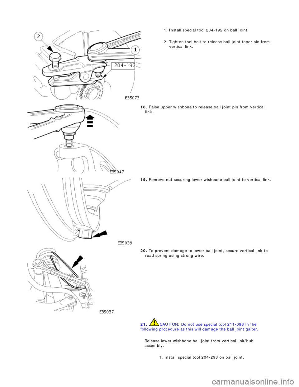
1.
Install special tool 204-192 on ball joint.
2. Tighten tool bolt to rele ase ball joint taper pin from
vertical link.
18 . Raise
upper wishbone to release
ball joint pin from vertical
link.
19 . R
emove nut securing lower wishbone
ball joint to vertical link.
20. To
prevent damage to lower ball
joint, secure vertical link to
road spring using strong wire.
21. CAUTION: Do not use special tool 211-098 in the
following procedure as this will damage the ball joint gaiter.
Release lower wishbone ball joint from vertical link/hub
assembly. 1. Install special tool 204-293 on ball joint.
Page 163 of 2490
I
nstallation
2
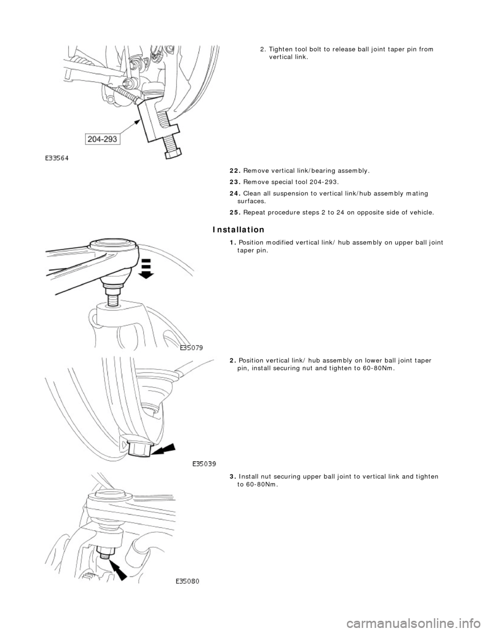
. Tighten tool bolt to rele
ase ball joint taper pin from
vertical link.
22. Remove vertical link/bearing assembly.
23. Remove special tool 204-293.
24. Clean all suspension to vertical link/hub assembly mating
surfaces.
25. Repeat procedure steps 2 to 24 on opposite side of vehicle.
1. Position modi
fied vertical link/
hub assembly on upper ball joint
taper pin.
2. Position verti
cal link/ hub asse
mbly on lower ball joint taper
pin, install securing nut and tighten to 60-80Nm.
3. Install nu
t securing upper ball jo
int to vertical link and tighten
to 60-80Nm.
Page 164 of 2490

4. Po
sition tie rod ball joint taper
pin on steering arm and install
and tighten securing nut to 71-85Nm.
5. Instal
l wheel speed sensor.
Positi
on wheel speed sensor on vertical link.
Inst
al
l sensor securing bolt
and tighten to 8-10Nm.
6. Remove wire temporarily securing vertical link to road spring.
7. Install br ake disc.
8. Re
lease tension on road spring.
Ro
tate adjuster of special tool 204-111 to release spring
tension.
R e
move special tool and adaptor from spring.
9. Position new link ass
embly on
lower wishbone and install but
do not tighten bolt.
10. Position new link arm ball joint stud in stabilizer bar and
install but do not tighten nut.
Page 165 of 2490

11
.
Tighten new link arm to wishbone nut and bolt to 41-54Nm.
12
.
Secure new link arm to stabilizer bar.
Tigh
ten link arm to stabilizer bar nut to 60-80Nm.
Check that ball
joint freed
om of movement has been
maintained.
13. Install road wheel. Refer to 74.20.05.
14. Repeat procedure steps 1 to 13 on opposite side of vehicle.
15. Raise front of vehicle, remove stands and lower vehicle.
16. Carry out steering geometry an d wheel alignment checks and
if necessary adjust. Refer to 57.65.01.
Page 166 of 2490

Rear Su
spension -
Lubric
ants, Fluids, Sealants and Adhesives
Torques
UnitSp
ecification
Loctite27
0
Greas eShell Retin a
x 'A'
Greas
eCastro l 'NT
R'
Com
p
onent
Nm
N
u
t - hub to axle shaft
3
04 -
336
Nu
t -
hub carrier pivot pin
88
-
118
Bol
t
- ABS sensor to hub carrier
8-1
0
Nu
t - stabilizer bar link to lower wishbone.
30
-40
Nu
t - stabilizer bar to link assembly.
30
-40
Bolts -
monostrut to body mounting brackets
88
-
118
Bolt
s
- monostrut to wishbone tie assembly
77
-
103
Bolts
- bu
mp stop to body
26
-34
Bol t
- damper lower mounting
80
-
100
N
u
t - damper top
31
-39
Bolts -
damper mounting plate to body
17
-23
Page 170 of 2490
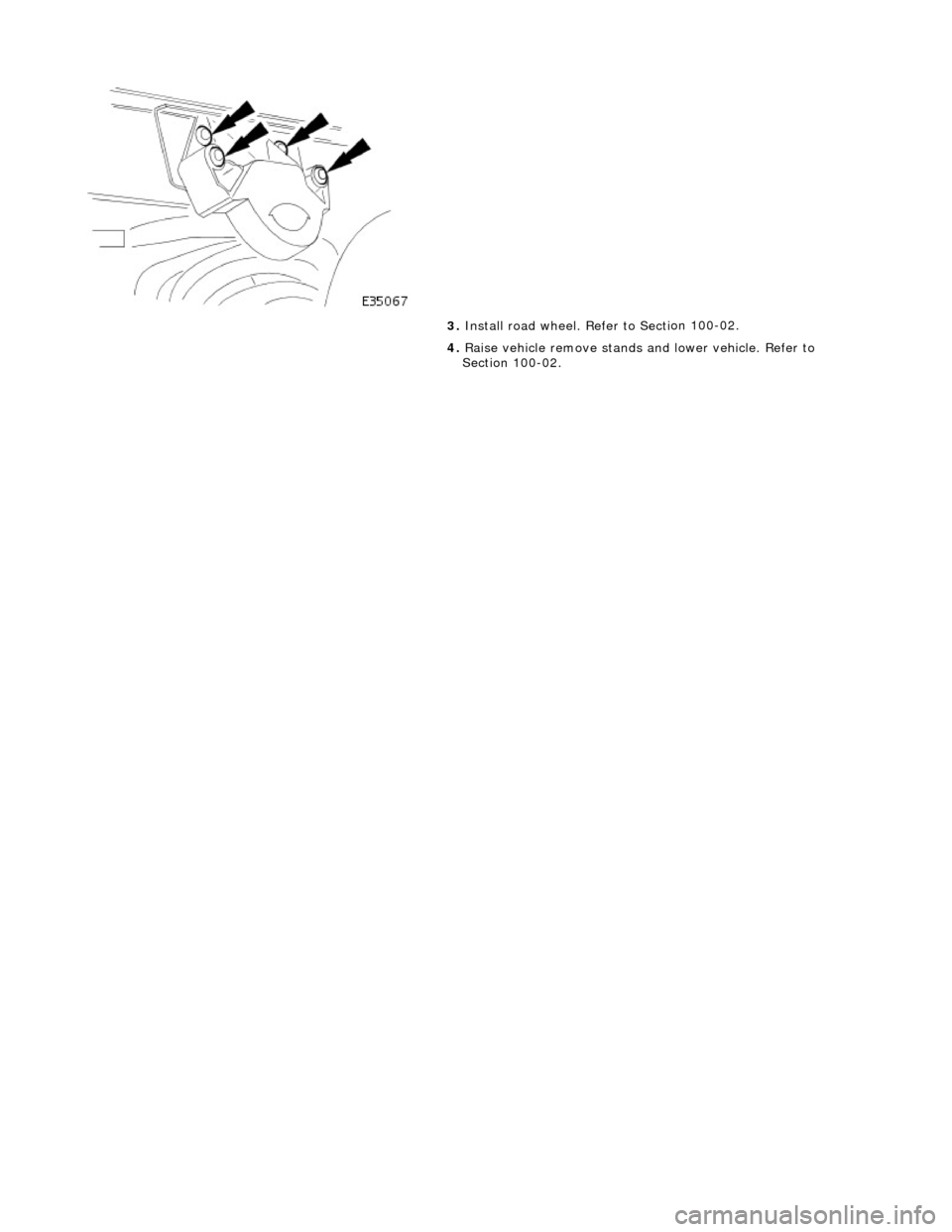
3.
Install road wheel. Re fer to Secti
on 100-02.
4. Raise vehicle remove stands and lower vehicle. Refer to
Section 100-02.
Page 173 of 2490
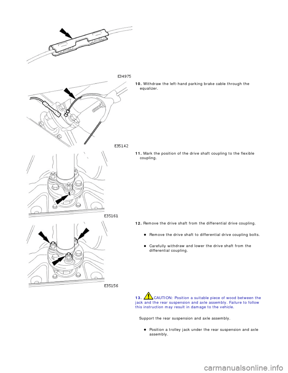
10
.
Withdraw the left-hand parking brake cable through the
equalizer.
11
.
Mark the position of the drive shaft coupling to the flexible
coupling.
12
.
Remove the drive shaft from the differential drive coupling.
R
emove the drive shaft to differential drive coupling bolts.
Carefully with
draw and lower the drive shaft from the
differential coupling.
13. CAUTION: Position a suitable piece of wood between the
jack and the rear suspension and axle assembly. Failure to follow
this instruction may result in damage to the vehicle.
Support the rear suspension and axle assembly.
Posi
tion a trolley jack under the rear suspension and axle
assembly.
Page 175 of 2490
I
nstallation
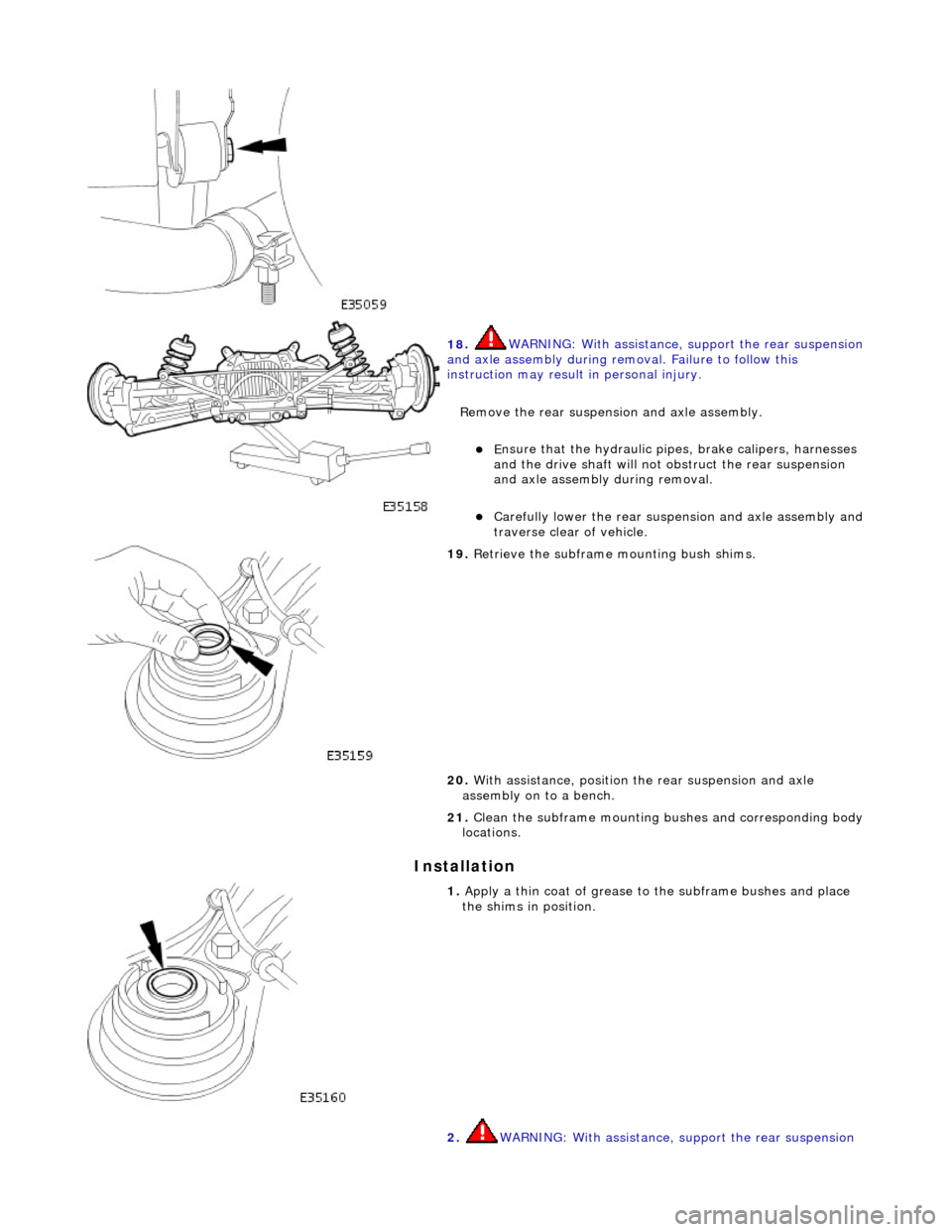
18
.
WARNING: With assistance, support the rear suspension
and axle assembly during remo val. Failure to follow this
instruction may result in personal injury.
Remove the rear suspensi on and axle assembly.
E
nsure that the hydr
aulic pipes, brake calipers, harnesses
and the drive shaft will not obstruct the rear suspension
and axle assembly during removal.
Carefull
y lower the rear suspen
sion and axle assembly and
traverse clear of vehicle.
19
.
Retrieve the subframe mounting bush shims.
20. With assistance, position th e rear suspension and axle
assembly on to a bench.
21. Clean the subframe mounting bushes and corresponding body
locations.
1. Apply a th
in coat of grease to the subframe bushes and place
the shims in position.
2. WARNING: With assistance, support the rear suspension