Speed Sensor JAGUAR X308 1998 2.G Repair Manual
[x] Cancel search | Manufacturer: JAGUAR, Model Year: 1998, Model line: X308, Model: JAGUAR X308 1998 2.GPages: 2490, PDF Size: 69.81 MB
Page 1179 of 2490
generates a signal when th
e dr
ive plate passes the sensor
sen
ds the ECM signals indicating crankshaft position and engine speed
is e
ssential for calculating spark timing
En
gine Coolant Temperature (ECT) Sensor
sen
ds the ECM a signal indicating the temperature of the engine coolant
is a t
emperature dependent resistor with a negative temperature coefficient (resistance changes inversely with
respect to temperature) and is constantly monitored by the ECM
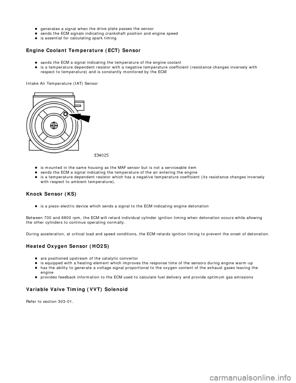
Intake Air Temperature (IAT) Sensor
is m
ounted in the same housing as the MA
F sensor but is not a serviceable item
sen
ds the ECM a signal indicating the temperature of the air entering the engine
is a t
emperature dependent resistor which has a negative
temperature coefficient (its resistance changes inversely
with respect to ambient temperature).
Knock S
ensor (KS)
is a pi
ezo-electric device which sends a signal
to the ECM indicating engine detonation
Between 700 and 6800 rpm, the ECM will retard individual cylinder ignition timing when detonation occurs while allowing
the other cylinders to continue operating normally.
During acceleration, at critical load and speed conditions, the ECM retards ignition timing to prevent the onset of detonation.
H
eated Oxygen Sensor (HO2S)
are
positioned upstream of the catalytic convertor
is equipped with
a heating element wh
ich improves the response time of the sensors during engine warm-up
h
as the ability to generate a voltage signal proportional to the oxygen content of the exhaust gases leaving the
engine
pr
ovides feedback information to the ECM used to calc
ulate fuel delivery and provide optimum gas emissions
Variable V
alve Timing (VVT) Solenoid
R
efer to section 303-01.
Page 1191 of 2490
Fue
l pump
Engine coolan
t temperature
(ECT) sensor
Blocked part-load breather (
service action S474)
Injec
tor leak
Emiss
ions
.
Check bull
etins for throttle cleaning procedure.
Check fuel pressure. For ECT sensor circuit tests,
GO to Pinpoint Test C.
. Refer to Servi
ce action
S474 for part-load breather procedure. For
injector leak test, Refer to technical service bulletin 303-39.
D
ifficult to start after hot
soak (vehicle standing
after engine has reached operating temperature)
Roc
hester valve
Thr
ottle contaminated
Purge
valve
Fue
l pump
Engine coolan
t temperature
(ECT) sensor
Blocked part-load breather (
service action S474)
Injec
tor leak
Engine cranks too
fa
st/slow
Batt
ery
Starter relay Harness Cyl
inder compression loss
(NA short term only. Refer to technical service bulletin; 303-39)
R
efer to service action
S491
F
or battery information,
REFER to Section 414
-0
1 Battery, Mounting and
Cables.
F
or starting system.
REFER to Section 303
-06 Sta
rting System
.
R
efer to technical servic
e bulletins and service
actions.
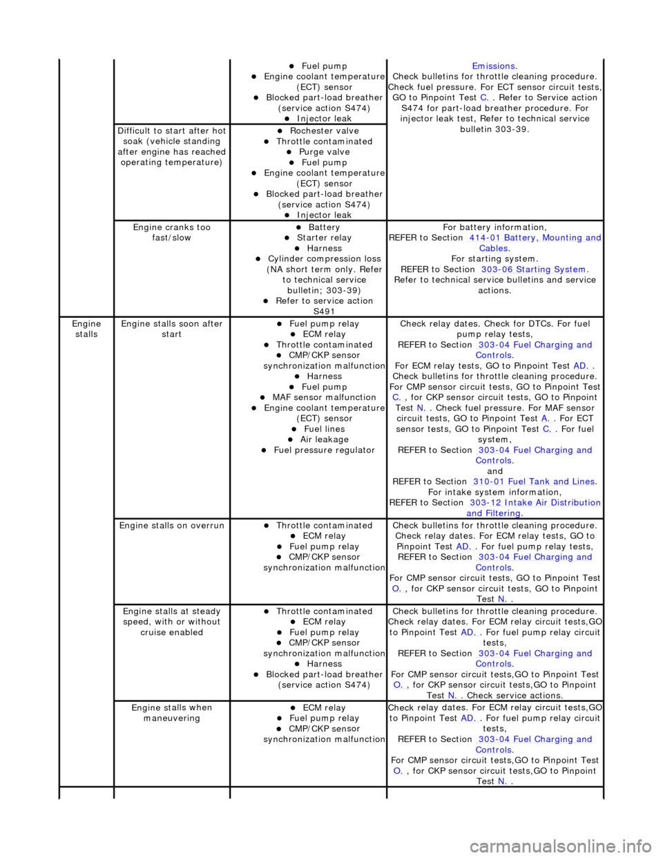
Engine
stalls
Engine st
alls soon after
start
F
uel pump relay
ECM relay Thr
ottle contaminated
CMP/CKP sen
sor
synchronization malfunction
Harness Fue
l pump
MAF
sensor malfunction
Engine coolan
t temperature
(ECT) sensor
Fue
l lines
Air leakage
F
uel pressure regulator
Check r
elay dates. Chec
k for DTCs. For fuel
pump relay tests,
REFER to Section 303
-0
4 Fuel Charging and
Controls.
F
or ECM relay tests, GO to Pinpoint Test
AD.
.
Check bull
etins for throttle cleaning procedure.
For CMP sensor circuit test s, GO to Pinpoint Test
C.
, for
CKP sensor circuit tests, GO to Pinpoint
Test N.
. Check fuel
pressure. For MAF sensor
circuit tests, GO to Pinpoint Test A.
. For EC
T
sensor tests, GO to Pinpoint Test C.
. F
or fuel
system,
REFER to Section 303
-0
4 Fuel Charging and
Controls.
and
REF
ER to Section 310
-0
1 Fuel Tank and Lines
. F
or intake system information,
REFER to Section 303
-1
2 Intake Air Distribution
and F
iltering
.
Engine
stalls on overrun
Thr
ottle contaminated
ECM relay F
uel pump relay
CMP/CKP sen
sor
synchronization malfunction
Check bull
etins for throttle cleaning procedure.
Check relay dates. For ECM relay tests, GO to Pinpoint Test AD.
. F
or fuel pump relay tests,
REFER to Section 303
-0
4 Fuel Charging and
Controls.
F
or CMP sensor circuit test
s, GO to Pinpoint Test
O.
, for
CKP sensor circuit tests, GO to Pinpoint
Test N.
.
E
ngine stalls at steady
speed, with or without cruise enabled
Thr
ottle contaminated
ECM relay F
uel pump relay
CMP/CKP sen
sor
synchronization malfunction
Harness Blocked part-load breather
(
service action S474)
Check bull
etins for throttle cleaning procedure.
Check relay dates. For EC M relay circuit tests,GO
to Pinpoint Test AD.
. F
or fuel pump relay circuit
tests,
REFER to Section 303
-0
4 Fuel Charging and
Controls.
F
or CMP sensor circuit test
s,GO to Pinpoint Test
O.
, for
CKP sensor circuit tests,GO to Pinpoint
Test N.
. Che
ck service actions.
Engine st
alls when
maneuvering
ECM relay F
uel pump relay
CMP/CKP sen
sor
synchronization malfunction
Check r
elay dates. For EC
M relay circuit tests,GO
to Pinpoint Test AD.
. F
or fuel pump relay circuit
tests,
REFER to Section 303
-0
4 Fuel Charging and
Controls.
F
or CMP sensor circuit test
s,GO to Pinpoint Test
O.
, for
CKP sensor circuit tests,GO to Pinpoint
Test N.
.
Page 1192 of 2490
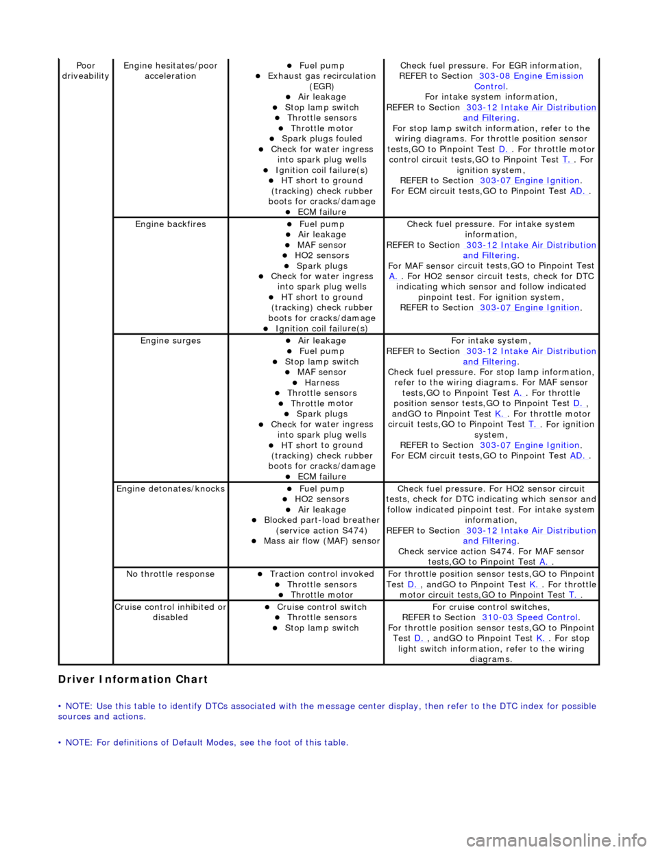
Driver Information
Chart
•
NOTE: Use this table to identify DTCs associated with the me
ssage center display, then refer to the DTC index for possible
sources and actions.
• NOTE: For definitions of Default Modes, see the foot of this table.
Poor
dr iveabilityEngine h e
sitates/poor
acceleration
Fue l
pump
Exhaus
t gas
recirculation
(EGR)
Air leakage Stop lamp swi t
ch
Throttl
e
sensors
Throttl
e
motor
Spark
plugs
fouled
Check f
o
r water ingress
into spark plug wells
Ignition coil fail
ure(s)
HT sh
o
rt to ground
(tracking) check rubber
boots for cracks/damage
ECM failu r
e
Check f
u
el pressure. For EGR information,
REFER to Section 303
-08 En gin
e Emission
Control.
F or i
ntake system information,
REFER to Section 303
-1 2
Intake Air Distribution
and F
ilt
ering
.
F or stop l
amp switch in
formation, refer to the
wiring diagrams. For throttle position sensor
tests,GO to Pinpoint Test D.
. Fo
r throttle motor
control circuit tests,GO to Pinpoint Test T.
. For
igni t
ion system,
REFER to Section 303
-07 En
gine Ignition
.
F or ECM
circuit tests,GO to Pinpoint Test
AD.
.
Engine backfiresFuel
pump
Air leakage MAF se
nsor
HO2 sensors
Spark plugs Check fo
r water ingress
into spark plug wells
HT sh o
rt to ground
(tracking) check rubber
boots for cracks/damage
Ignition coil fail
ure(s)
Chec
k fu
el pressure. For intake system
information,
REFER to Section 303
-12
Intake Air Distribution
and Filt
ering
.
F or MAF sensor ci
rcuit test
s,GO to Pinpoint Test
A.
. F or HO2 sensor
circui
t tests, check for DTC
indicating which sensor and follow indicated pinpoint test. For ignition system,
REFER to Section 303
-07 En
gine Ignition
.
Engine
s
urges
Air leakage
Fuel
pump
Stop lamp swit
ch
MAF s
e
nsor
Harness Throttl
e
sensors
Throttl
e
motor
Spark plugs
Check fo
r water ingress
into spark plug wells
HT sh o
rt to ground
(tracking) check rubber
boots for cracks/damage
ECM failu r
e
Fo
r
intake system,
REFER to Section 303
-1 2
Intake Air Distribution
and Filt
ering
.
Check fu
el pressure. For
stop lamp information,
refer to the wiring diagrams. For MAF sensor tests,GO to Pinpoint Test A.
. Fo
r throttle
position sensor tests,GO to Pinpoint Test D.
,
a n
dGO to Pinpoint Test
K.
. Fo
r throttle motor
circuit tests,GO to Pinpoint Test T.
. For ig
nition
system,
REFER to Section 303
-07 En
gine Ignition
.
F or ECM
circuit tests,GO to Pinpoint Test
AD.
.
Engine detonates/k
nocks
Fue
l
pump
HO2 sensors
Air leakage Blocked part-load breather
(s
ervice action S474)
Mass ai
r fl
ow (MAF) sensor
Chec
k fu
el pressure. Fo
r HO2 sensor circuit
tests, check for DTC indicating which sensor and
follow indicated pinpoint test. For intake system
information,
REFER to Section 303
-1 2
Intake Air Distribution
and Filt
ering
.
Check service action S474
. For MAF sensor
tests,GO to Pinpoint Test A.
.
No t
hrottle response
Traction contr
o
l invoked
Throttl
e
sensors
Throttl
e
motor
Fo
r th
rottle position sensor tests,GO to Pinpoint
Test D.
, andG O to Pinpoint
Test
K.
. Fo
r throttle
motor circuit tests,GO to Pinpoint Test T.
.
Cru i
se control inhibited or
disabled
Cru i
se control switch
Throttle
sensors
Stop lamp swit
ch
For cru
i
se control switches,
REFER to Section 310
-03
Speed Control
.
For th
rottle position sensor tests,GO to Pinpoint
Test D.
, andG O to Pinpoint
Test
K.
. For s t
op
light switch information, refer to the wiring diagrams.
Page 1201 of 2490

leak
/blockage
EVAP valve failure
P0444Evaporati
ve emissions system
(EVAP) valve circuit open circuit
EVAP t
o ECM drive circuit open
circuit or high resistance
EVAP failu
re
F
or evaporative emissions pinpoint
tests,
REFER to Section 303
-1
3 Evaporative
Emiss
ions
.
P0445Evaporati
ve emissions system
(EVAP) valve circuit short circuit
E
VAP to ECM drive circuit short
circuit to ground
EVAP failu
re
F
or evaporative emissions pinpoint
tests,
REFER to Section 303
-1
3 Evaporative
Emiss
ions
.
P0447Cani
ster close valve (CCV) circuit
open circuit
CCV to ECM
drive circuit open
circuit, high resi stance or short
circuit to ground
EVAP failu
re
F
or evaporative emissions pinpoint
tests,
REFER to Section 303
-1
3 Evaporative
Emiss
ions
.
P0448Cani
ster close valve (CCV) circuit
short circuit
CCV to
ECM drive circuit short
circuit to high voltage
CCV failure
F
or evaporative emissions pinpoint
tests,
REFER to Section 303
-1
3 Evaporative
Emiss
ions
.
P0452F
uel tank pressure (FTP) sensor
circuit low voltage
FTP
sensor disconnected
FTP
sensor to ECM sense circuit
open circuit or short circuit to
ground
FTP sen
sor to ECM power supply
circuit open circuit or short circuit
to ground
F
TP sensor failure
F
or evaporative emissions pinpoint
tests,
REFER to Section 303
-1
3 Evaporative
Emiss
ions
.
P0453F
uel tank pressure (FTP) sensor
circuit high voltage
FTP
sensor to ECM signal ground
circuit open circuit
F
TP sensor to ECM wiring (supply,
sense, signal, ground) short circuit
to each other
FTP
sensor to ECM sense circuit
short circuit to high voltage
F
TP sensor failure
F
or evaporative emissions pinpoint
tests,
REFER to Section 303
-1
3 Evaporative
Emiss
ions
.
P0460Fue
l level sense signal
performance
Fue
l level sensor
to instrument
cluster circuits in termittent short or
open circuit
F
uel level sensor failure
Instrument cluster
faul
t (incorrect
fuel level data)
F
or fuel level sensor
circuit tests,
REFER to Section 303
-04
Fuel
Charging and Con
trols
.
P0506Idl
e rpm lower than expected
Ai
r intake blockage
Acce
ssory drive overload
(defective/siezed component)
Thr
ottle valve stuck closed
Throttl
e assembly failure
Chec
k the air intake system.
REFER to Section 303
-1
2 Intake Air
Distribu
tion and Filtering
.
Check t
he accessory drive
components,
REFER to Section 303
-0
5 Accessory
Dr
ive
.
F
or throttle body information,
REFER to Section 303
-04
Fuel
Charging and Con
trols
.
P0507Idle rpm
higher than expected
Inta
ke air leak between MAF
sensor and throttle
Inta
ke air leak between throttle
and engine
Engine
breather leak
Cruis
e (speed) control vacuum
failure
Thr
ottle valve stuck open
Throttl
e assembly failure
Chec
k the air intake system.
REFER to Section 303
-1
2 Intake Air
Distribu
tion and Filtering
.
Chec
k the engine breather system,
REFER to Section 303
-08
Engine
Emissi
on Control
.
F
or cruise (speed) control information,
REFER to Section 310
-03
Speed
Control.
F
or throttle body information,
REFER to Section 303
-04
Fuel
Charging and Con
trols
.
P0560Vehicle voltage
malfunction
ECM battery
power supply open
circuit, high resistance
F
or ECM power supply circuit tests,
GO to Pinpoint Test AD.
.
P0566Cruise (speed) contr
ol
CANCEL
switch ON fault
Cru
ise (speed) control switches
internal steering wheel short circuit
to ground
For cru
ise (speed) control circuit tests,
REFER to Section 310
-03
Speed
Page 1202 of 2490

St
eering wheel cassette reel short
circuit to ground
Cassette reel to ECM c
ircuit short
circuit to ground
CANC EL
switch failure (stuck ON)
Control.
P0567Cruise (speed) contr
o
l
RESUME
switch ON fault
Cru i
se (speed) control switches
internal steering wheel short circuit
to ground
S t
eering wheel cassette reel short
circuit to ground
Cassette reel to ECM c
ircuit short
circuit to ground
RESUME s
witch failure (stuck ON)
For cru
i
se (speed) control circuit tests,
REFER to Section 310
-03 Sp
eed
Control.
P0568Cru
i
se (speed) control switch
ground malfunction
Cru i
se (speed) control switches
internal steering wheel open circuit
St
eering wheel cassette reel open
circuit or high resistance
Cassette reel to ECM ci
rcuit
ACCEL/DECEL open circuit or high
resistance
ACC E
L/DECEL
switch failure
For crui
se (speed) control circuit tests,
REFER to Section 310
-03 Sp
eed
Control.
P0569Cruise (speed) contr
o
l
DECEL/SET (SET-) switch ON
fault
Cru i
se (speed) control switches
internal steering wheel short circuit
to ground
S t
eering wheel cassette reel short
circuit to ground
Cassette reel to ECM c
ircuit short
circuit to ground
DECE
L/SET
switch failure (stuck
ON)
For cru i
se (speed) control circuit tests,
REFER to Section 310
-03 Sp
eed
Control.
P0570Cruise (speed) contro
l
ACCEL/SET (SET+) switch ON
fault
Crui
se (speed) control switches
internal steering wheel short circuit
to ground
S t
eering wheel cassette reel short
circuit to ground
Cassette reel to ECM c
ircuit short
circuit to ground
ACC E
L/SET
switch failure (stuck
ON)
For crui
se (speed) control circuit tests,
REFER to Section 310
-03 Sp
eed
Control.
P0603ECM dat
a
corrupted
ECM failu
r
e
Contact deal
er techni
cal support for
advice on possible ECM failure.
P1000 Sy
stem checks not complete since
last memory clear
O B
D diagnostic monitors have not
completed
Carr y out comprehensi
ve component
monitor drive cycle. Refer to the DTC
section of JTIS.
P1104Mass ai r fl
ow (MAF) sensor ground
malfunction
MAF sensor to EC
M reference
ground circuit open circuit, short
circuit to high voltage, high
resistance
MAF s
ensor to ECM sensing circuit
open circuit
MAF sensor fai
lure
For MAF
se
nsor circuit tests,GO to
Pinpoint Test A.
.
P1111Syst
em checks complete since last
memory clear
O B
D diagnostic monitors have completed
N
o
action necessary.
P1112In
t
ake air temperature (IAT)
sensor 2 sense circuit high voltage
(low charge air temperature)
IAT sensor 2 di sconnect
ed
IAT sensor 2
to ECM sensing circuit
high resistance, open circuit or
short circuit to high voltage
IAT se nsor 2 failure
F
or IAT sensor
2 circuit tests,GO to
Pinpoint Test Q.
.
P1113Int
ake air temperature (IAT)
sensor 2 sense circuit low voltage
(high charge air temperature)
Supercharger interco
oler failure
IAT se
nsor 2
to ECM sensing circuit
short circuit to ground
IAT se nsor 2 failure
F
or IAT sensor
2 circuit tests,GO to
Pinpoint Test Q.
.
P1121Accele
rator pedal position (APP)
sensor circuit 'A'
range/performance
A P
P sensor to ECM sense circuit
'A' (sensor pin 5) open circuit,
short circuit or high resistance
Sensor power su pply fault
Sensor r
e
ference ground fault
APP s
e
nsor failure
For APP
sen
sor circuit tests,GO to
Pinpoint Test R.
, andGO to Pinpoint
Test S.
.
Page 1205 of 2490
TP se
nsor to ECM sensing circuits
('1' or '2') short circuit to high
voltage
TP sensor
failure
Throttl
e motor disconnected
Th
rottle motor to ECM drive circuits
short circuit or open circuit
Throttl
e motor failure
Throttl
e assembly failure
Test
K. . F
or throttle motor circuit
tests,GO to Pinpoint Test T.
. For
throttle body i
nformation,
REFER to Section 303
-04
Fuel
Charging and Con
trols
.
P1252Mec
hanical gu
ard position
malfunction (cruise (speed)
control)
VSV 1, 2, 3 v
acuum and/or
electrical circuit fault(s) open
circuit, short circuit or high
resistance
Mechanica
l guard sensor to ECM
sense circuit
Mechanica
l guard sensor failure
Mechanica
l guard actuator
siezed/spring broken
Throttl
e vacuum actuator fault
Se
e pinpoint tests for components
listed.
P1253Mec
hanical gu
ard position
malfunction (engine off)
VSV 1, 2, 3 v
acuum and/or
electrical circuit fault(s)
Mechanica
l guard sensor to ECM
sense circuit
Mechanica
l guard sensor failure
Mechanica
l guard actuator
siezed/spring broken
Throttl
e vacuum actuator fault
Se
e pinpoint tests for components
listed.
P1260Se
curity input malfunction
K
TM to ECM circuit short circuit,
high resistance or open circuit
KTM failu
re
F
or KTM circuit tests,GO to Pinpoint
Test Y.
.
P1313M
isfire rate catalyst damage,
right-hand. NOTE: This DTC will
flag only when accompanied by a
random or individual cylinder
misfire DTC; P0300, P0301 to
P0304
R
efer to possible causes for P0300-P0308
R
efer to actions for P0300-P0308.
P1314Mi
sfire rate catalyst damage, left-
Hand: NOTE. This DTC will flag
only when accompanied by a
random or individual cylinder
misfire DTC; P0300 to P0308
P1316M
isfire excess emission. NOTE:
This DTC will flag only when
accompanied by an individual
cylinder misfire DTC; P0300 to
P0308
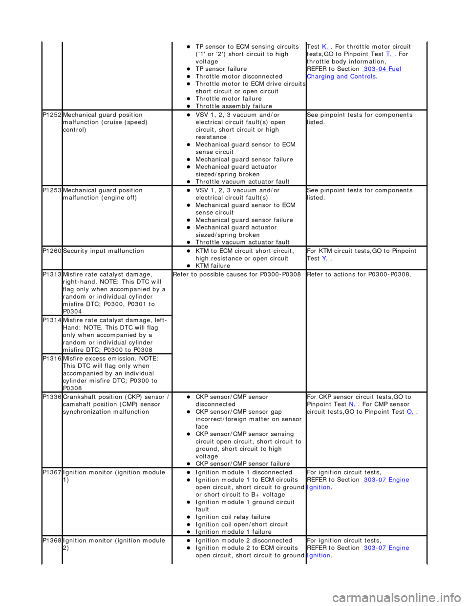
P1336Cranksh
aft position
(CKP) sensor /
camshaft position (CMP) sensor
synchronization malfunction
CKP s
ensor/CMP sensor
disconnected
CKP sensor/CM
P sensor gap
incorrect/foreign matter on sensor
face
CKP s
ensor/CMP sensor sensing
circuit open circuit, short circuit to
ground, short circuit to high
voltage
CKP s
ensor/CMP sensor failure
F
or CKP sensor circ
uit tests,GO to
Pinpoint Test N.
. For CM
P sensor
circuit tests,GO to Pinpoint Test O.
.
P1367Ignit
ion monitor (ignition module
1)
Ignition modu
le
1 disconnected
Ignition modul
e 1 to ECM circuits
open circuit, short circuit to ground
or short circuit to B+ voltage
Ignition modul
e 1 ground circuit
fault
Ignition coil
relay failure
Ignition coil
open/short circuit
Ignition modul
e 1 failure
F
or ignition circuit tests,
REFER to Section 303
-07
Engine
Ignition.
P1368Ignit
ion monitor (ignition module
2)
Ignition modu
le
2 disconnected
Ignition modul
e 2 to ECM circuits
open circuit, short circuit to ground
F
or ignition circuit tests,
REFER to Section 303
-07
Engine
Ignition.
Page 1206 of 2490
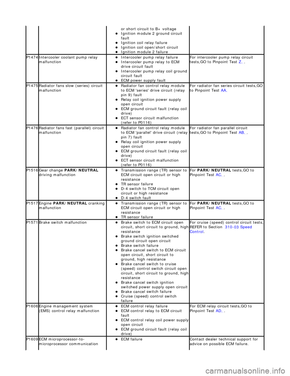
or sho
rt circuit to B+ voltage
Ignition modul
e
2 ground circuit
fault
Ignition coil relay fai
lure
Ignition coil
open/short
circuit
Ignition modul
e
2 failure
P1474Int
e
rcooler coolant pump relay
malfunction
Intercooler pump relay failure
Intercooler pump relay
to ECM
drive circuit fault
Intercooler pump relay coi
l ground
circuit fault
ECM power supply f
ault
F
or i
ntercooler pump relay circuit
tests,GO to Pinpoint Test Z.
.
P1475Ra
diator fans slow
(series) circuit
malfunction
R a
diator fan control relay module
to ECM 'series' drive circuit (relay
pin 9) fault
Relay coil ignition power supply
o p
en circuit
ECM ground circuit fault (relay coil
drive)
ECT se ns
or circuit malfunction
(refer to P0116)
F o
r radiator fan seri
es circuit tests,GO
to Pinpoint Test AA.
P1476Ra
diator fans fast (parallel) circuit
malfunction
R a
diator fan control relay module
to ECM 'parallel' drive circuit (relay
pin 7) fault
Relay coil ignition power supply
o p
en circuit
ECM ground circuit faul
t (relay coil
drive)
ECT sens
or circuit malfunction
(refer to P0116)
F or radi
ator fan parallel circuit
tests,GO to Pinpoint Test AB.
.
P1516Gear change PARK
/NEUTRAL
driving malfunction
Transmission range (T
R) sensor to
ECM circuit open circuit or high
resistance
TR sensor f
ailure
D-
4
switch to TCM circuit open
circuit or high resistance
D-4 swi
tch fault
For
PARK/NEUTRAL tests,GO to
Pinpoint Test AC.
.
P1517Engine PA
RK/NEUTRAL
cranking
malfunction
Transmissi on range (T
R) sensor to
ECM circuit open circuit or high
resistance
TR sensor f
ailure
Fo
r
PARK/NEUTRAL tests,GO to
Pinpoint Test AC.
.
P1571Brake swit
ch malfunction
Brake sw
it
ch to ECM circuit open
circuit, short circ uit to ground, high
resistance
Brake sw it
ch ignition switched
ground circuit open circuit
Brake sw it
ch failure
Brake ca
ncel
switch to ECM circuit
open circuit, short circuit to
ground, high resistance
Brake ca nce
l switch to cruise
(speed) control switch circuit open
circuit, short circ uit to ground, high
resistance
Brake cance
l switch ignition
switched power supply open circuit
Brake ca nce
l switch failure
Cru
i
se (speed) control switch
failure
For cru i
se (speed) control circuit tests,
REF
E
R to Section 310
-03
Sp
eed
Control.
P1606Engine
m
anagement system
(EMS) control relay malfunction
ECM co ntrol rel
ay failure
ECM c
o
ntrol relay to ECM circuit
fault
ECM co ntrol rel
ay coil power supply
open circuit
ECM ground circuit faul t (relay coil
drive)
F or ECM
relay circuit tests,GO to
Pinpoint Test AD.
.
P1609EC
M microprocessor-to-
microprocessor communication
ECM failu r
e
Contact deal
er techni
cal support for
advice on possible ECM failure.
Page 1242 of 2490
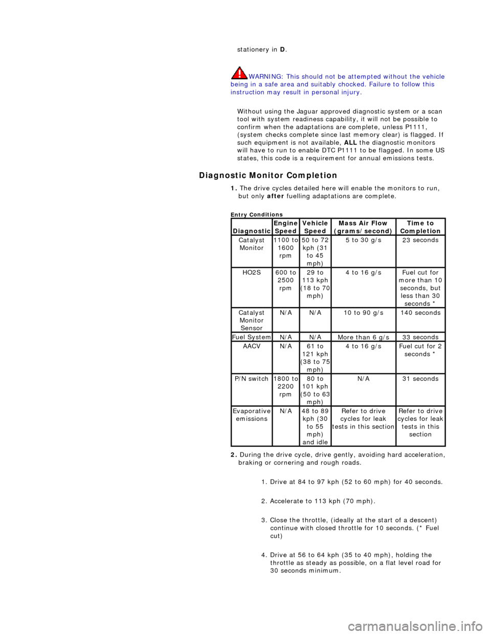
Diagnostic Monitor Comp
letion
stat
ionery in
D.
WARNING: This should not be attempted without the vehicle
being in a safe area and suitably chocked. Failure to follow this
instruction may result in personal injury.
Without using the Jaguar approved diagnostic system or a scan
tool with system readiness capability, it will not be possible to
confirm when the adaptations are complete, unless P1111,
(system checks complete since last memory clear) is flagged. If
such equipment is not available, ALL the diagnostic monitors
will have to run to enable DTC P1111 to be flagged. In some US
states, this code is a requirem ent for annual emissions tests.
1. The dri v
e cycles detailed here w
ill enable the monitors to run,
but only after fuelling adaptations are complete.
Entry C
onditions
Di
agno
stic
Engine
S p
eed
Ve
h
icle
Speed
Mass Air Flow
(gra ms/sec
ond)
Ti
m
e to
Completion
Catalyst Monitor1 100
to
1600 rpm
50 to
72
kph (31 to 45
mph)
5 to
30 g/s
23
se
conds
HO2S6
00 t
o
2500 rpm
29 to
113 kph
(18 to 70
mph)
4 to
16 g/s
F
u
el cut for
more than 10 seconds, but less than 30 seconds *
Catalyst Monitor SensorN/ AN/A10
to 90 g/s
14
0
seconds
F
u
el System
N/
AN/AMore than 6 g/s33 se
conds
AACVN/
A61 to
121 kph
(38 to 75
mph)
4 to
16 g/s
F
u
el cut for 2
seconds *
P /
N switch
1
800
to
2200 rpm
80 to
101 kph
(50 to 63
mph)
N/ A31 se
conds
Evaporative
em is
sions
N/
A48 to
89
kph (30 to 55
mph)
and idle
R e
fer to drive
cycles for leak
tests in this section
Re
fer to drive
cycles for leak
tests in this section
2. During the drive cycle, drive gent ly, avoiding hard acceleration,
braking or cornering and rough roads.
1. Drive at 84 to 97 kph (52 to 60 mph) for 40 seconds.
2. Accelerate to 113 kph (70 mph).
3. Close the throttle, (ideally at the start of a descent)
continue with closed throttle for 10 seconds. (* Fuel
cut)
4. Drive at 56 to 64 kph (35 to 40 mph), holding the throttle as steady as possib le, on a flat level road for
30 seconds minimum.
Page 1261 of 2490
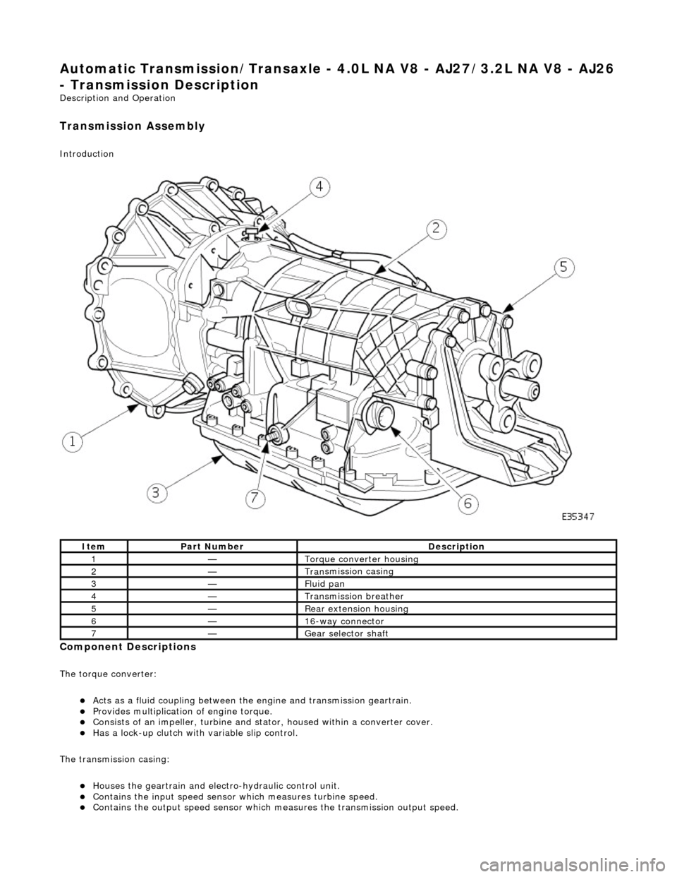
Automatic Transmission/Transaxle - 4.0L NA V8 - AJ27/3.2L NA V8 - AJ26
- Transmission Descriptio
n
Description an
d Operation
Transmission As
sembly
Int
roduction
Compon
ent Descriptions
The t
orque converter:
Acts as a fluid
coupling between the
engine and transmission geartrain.
P
rovides multiplication of engine torque.
Cons
ists of an impeller, turbine and stat
or, housed within a converter cover.
Has a l
ock-up clutch with variable slip control.
The transmission casing:
Houses the geartrain and elec t
ro-hydraulic control unit.
Contains
the input speed sensor which measures turbine speed.
Contai
ns the output speed sensor which measures the transmission output speed.
It
em
Par
t Number
De
scription
1—Torque c
onverter housing
2—Tran
smission casing
3—Fluid pan
4—Transmission bre
ather
5—Re
ar extension housing
6—16
-way connector
7—Gear s
elector shaft
Page 1267 of 2490
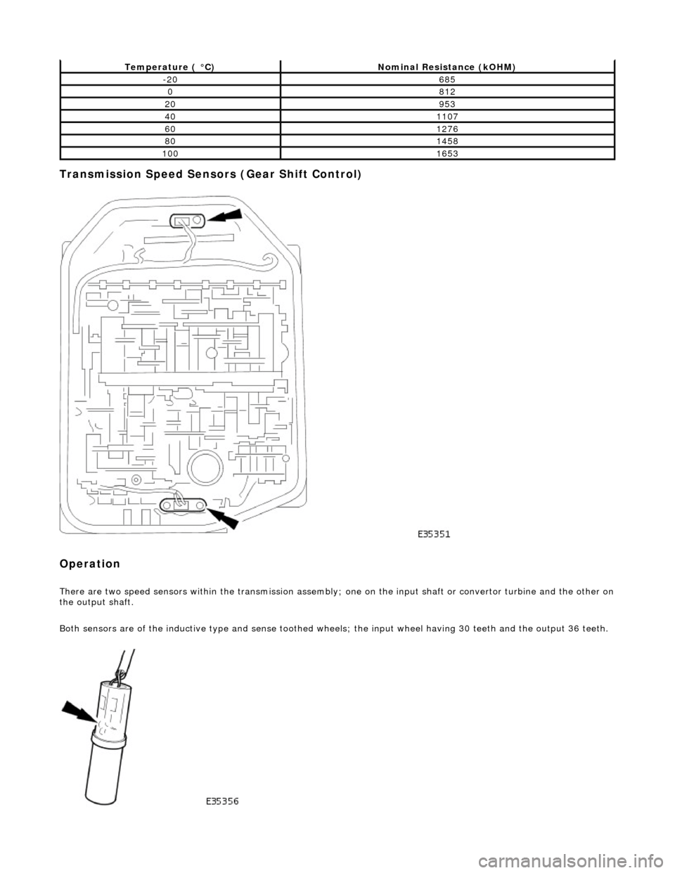
Transmission Speed Sensors (Gear Shift Control)
Operation
There are two speed sensors within the transmission assembly; one on the input shaft or convertor turbine and the other on the output shaft.
Both sensors are of the inductive type and sense toothed wheels; the input wheel having 30 teeth and the output 36 teeth.
Temperature ( °C)Nominal Resistance (kOHM)
-20685
0812
20953
401107
601276
801458
1001653