box JAGUAR XFR 2010 1.G Owner's Guide
[x] Cancel search | Manufacturer: JAGUAR, Model Year: 2010, Model line: XFR, Model: JAGUAR XFR 2010 1.GPages: 3039, PDF Size: 58.49 MB
Page 260 of 3039

DTC Description Possible Causes Action suspect. P0783-77
3-4 Shift - Commanded
position not reachable
Gear Ratio Monitoring.
Mechanical Failures
Check and correct oil level. Clear DTC. If code
re-detects suspect Transmission (mechanical)
internal fault. Install a new Transmission as
required, refer to the warranty policy and
procedures manual if a module/component is
suspect. P0784-07
4-5 Shift - Mechanical
Failures
Gear Ratio Monitoring.
Mechanical Failures
Check and correct oil level. Clear DTC. If code
re-detects suspect Transmission (mechanical)
internal fault. Install a new Transmission as
required, refer to the warranty policy and
procedures manual if a module/component is
suspect. P0784-77
4-5 Shift - Commanded
position not reachable
Gear Ratio Monitoring.
Mechanical Failures
Check and correct oil level. Clear DTC. If code
re-detects suspect Transmission (mechanical)
internal fault. Install a new Transmission as
required, refer to the warranty policy and
procedures manual if a module/component is
suspect. P0798-1A
Pressure Control Solenoid
C Electrical - Circuit
Resistance Below Threshold
Pressure control solenoid
C Circuit resistance below
threshold
Suspect the Transmission Control Module. Install a
new Transmission Control Module as required,
refer to the warranty policy and procedures manual
if a module/component is suspect. P0798-1E
Pressure Control Solenoid
C Electrical - Circuit Short
to Ground
Pressure control solenoid
C electrical circuit short
to ground
Suspect the Transmission Control Module. Install a
new Transmission Control Module as required,
refer to the warranty policy and procedures manual
if a module/component is suspect. P0798-21
Pressure Control Solenoid
C Electrical - Signal
amplitude < minimum
Pressure Control Solenoid
C Electrical signal
amplitude < minimum
Suspect the Transmission Control Module. Install a
new Transmission Control Module as required,
refer to the warranty policy and procedures manual
if a module/component is suspect. P0814-62 Transmission Range
Display Circuit - Signal
compare failure
Transmission Range
Display Circuit signal
compare failure
Suspect the Transmission Control Module. Install a
new Transmission Control Module as required,
refer to the warranty policy and procedures manual
if a module/component is suspect. P0826-08
Up and Down Switch
circuit - Bus Signal
Message Failures
Invalid CAN signal from
Central Junction
Box/Instrument Cluster
Stuck Sprintronic switch
CAN bus circuit fault
Check Central Junction Box and Instrument Cluster
for stored DTCs. Check gear change switches for
correct operation. Refer to circuit diagrams and
check CAN bus for a circuit fault P0826-81
Up and Down Switch
Circuit - Invalid serial
data received
Invalid Can signal from
Central Junction Box /
Instrument Cluster
Stuck Sprintronic switch
CAN Bus Circuit fault
Check Central Junction Box and Instrument Cluster
for stored DTCs. Check Gear Change Switches for
correct operation. Refer to Circuit diagrams and
check CAN Bus for Circuit fault P0826-88
Up and Down Switch
Circuit - Bus off
Steering Wheel Module to
Central Junction Box /
Instrument Cluster LIN
Bus failure
Check Central Junction Box and Steering Wheel
Ice Switches for stored DTCs. Refer to Circuit
diagrams and check LIN Bus for Circuit fault P0829-07
5-6 Shift - Mechanical
Failures
Gear Ratio Monitoring.
Mechanical Failures
Check and correct oil level. Clear DTC. If code
re-detects suspect Transmission (mechanical)
internal fault. Install a new Transmission as
required, refer to the warranty policy and
procedures manual if a module/component is
suspect. www.JagDocs.com
Page 267 of 3039
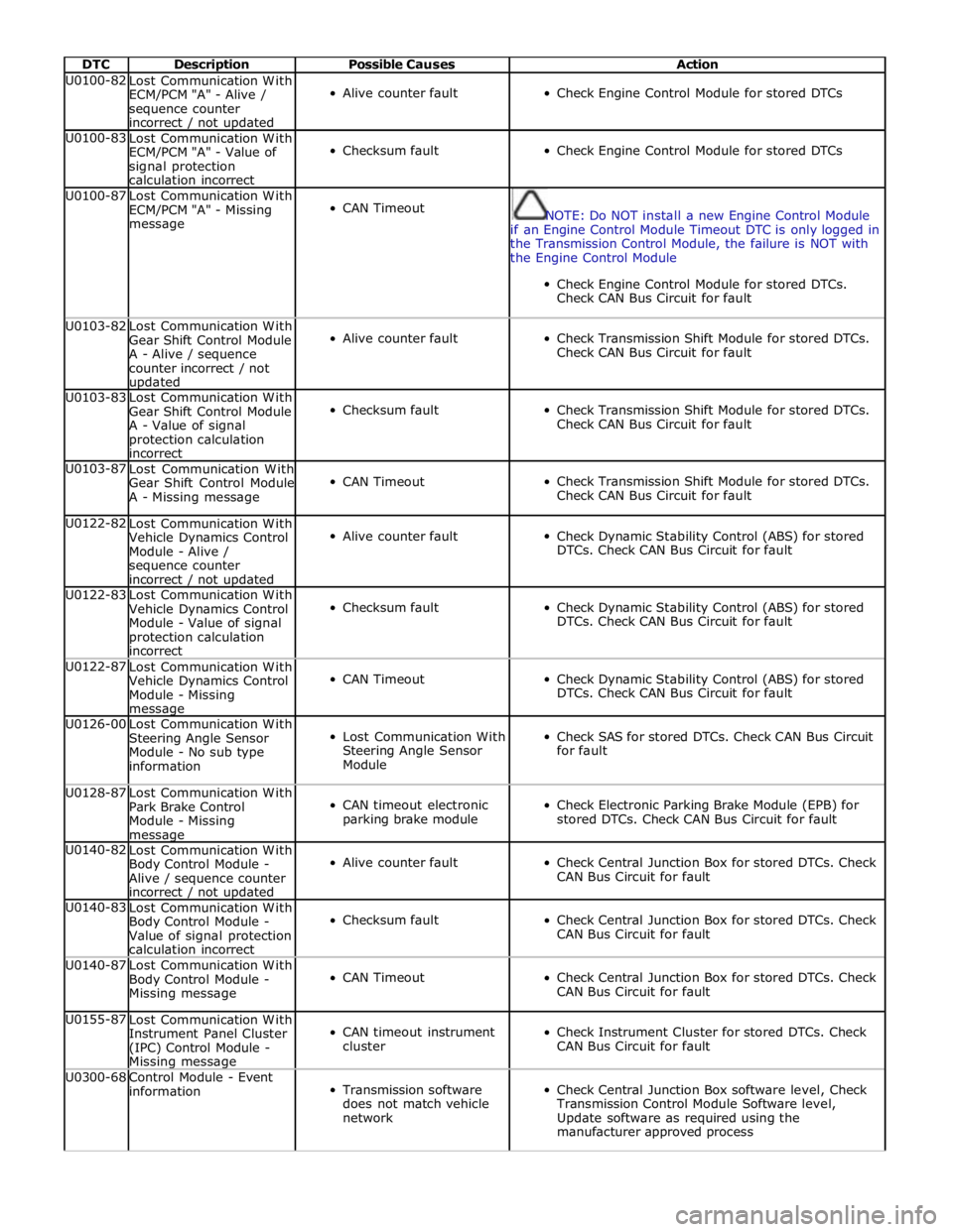
DTC Description Possible Causes Action U0100-82
Lost Communication With
ECM/PCM "A" - Alive /
sequence counter
incorrect / not updated
Alive counter fault
Check Engine Control Module for stored DTCs U0100-83
Lost Communication With
ECM/PCM "A" - Value of
signal protection
calculation incorrect
Checksum fault
Check Engine Control Module for stored DTCs U0100-87
Lost Communication With
ECM/PCM "A" - Missing
message
CAN Timeout
NOTE: Do NOT install a new Engine Control Module
if an Engine Control Module Timeout DTC is only logged in
the Transmission Control Module, the failure is NOT with
the Engine Control Module
Check Engine Control Module for stored DTCs.
Check CAN Bus Circuit for fault U0103-82
Lost Communication With
Gear Shift Control Module
A - Alive / sequence
counter incorrect / not updated
Alive counter fault
Check Transmission Shift Module for stored DTCs.
Check CAN Bus Circuit for fault U0103-83
Lost Communication With
Gear Shift Control Module
A - Value of signal
protection calculation
incorrect
Checksum fault
Check Transmission Shift Module for stored DTCs.
Check CAN Bus Circuit for fault U0103-87
Lost Communication With
Gear Shift Control Module
A - Missing message
CAN Timeout
Check Transmission Shift Module for stored DTCs.
Check CAN Bus Circuit for fault U0122-82
Lost Communication With
Vehicle Dynamics Control
Module - Alive /
sequence counter
incorrect / not updated
Alive counter fault
Check Dynamic Stability Control (ABS) for stored
DTCs. Check CAN Bus Circuit for fault U0122-83
Lost Communication With
Vehicle Dynamics Control
Module - Value of signal
protection calculation
incorrect
Checksum fault
Check Dynamic Stability Control (ABS) for stored
DTCs. Check CAN Bus Circuit for fault U0122-87
Lost Communication With
Vehicle Dynamics Control
Module - Missing message
CAN Timeout
Check Dynamic Stability Control (ABS) for stored
DTCs. Check CAN Bus Circuit for fault U0126-00
Lost Communication With
Steering Angle Sensor
Module - No sub type
information
Lost Communication With
Steering Angle Sensor
Module
Check SAS for stored DTCs. Check CAN Bus Circuit
for fault U0128-87
Lost Communication With
Park Brake Control
Module - Missing message
CAN timeout electronic
parking brake module
Check Electronic Parking Brake Module (EPB) for
stored DTCs. Check CAN Bus Circuit for fault U0140-82
Lost Communication With
Body Control Module -
Alive / sequence counter
incorrect / not updated
Alive counter fault
Check Central Junction Box for stored DTCs. Check
CAN Bus Circuit for fault U0140-83
Lost Communication With
Body Control Module -
Value of signal protection
calculation incorrect
Checksum fault
Check Central Junction Box for stored DTCs. Check
CAN Bus Circuit for fault U0140-87
Lost Communication With
Body Control Module -
Missing message
CAN Timeout
Check Central Junction Box for stored DTCs. Check
CAN Bus Circuit for fault U0155-87
Lost Communication With
Instrument Panel Cluster
(IPC) Control Module - Missing message
CAN timeout instrument
cluster
Check Instrument Cluster for stored DTCs. Check
CAN Bus Circuit for fault U0300-68
Control Module - Event
information
Transmission software
does not match vehicle
network
Check Central Junction Box software level, Check
Transmission Control Module Software level,
Update software as required using the
manufacturer approved process
Page 268 of 3039

DTC Description Possible Causes Action U0401-08
Invalid Data Received
From ECM/PCM A - Bus
Signal Message Failures
Inaccurate engine speed,
torque information
Check Engine Control Module for stored DTCs,
Check CAN Bus circuit for faults U0401-68
Invalid Data Received
from ECM/PCM A - Event
information
Inaccurate engine speed,
torque information
Check Engine Control Module for stored DTCs.
Check CAN Bus Circuit for fault U0401-86
Invalid Data Received
from ECM/PCM A - Signal
Invalid
Inaccurate engine speed,
torque information
Check Engine Control Module for stored DTCs.
Check CAN Bus Circuit for fault U0404-68
Invalid Data Received
from Gear Shift Control
Module A - Event
information
Incorrect CAN data
received from
Transmission Shift
Module
Check Transmission Shift Module for stored DTCs.
Refer to Circuit diagrams and check CAN and LIN
Bus for Circuit fault U0404-81
Invalid Data Received
from Gear Shift Control
Module A - Invalid Serial
Data Received
Incorrect LIN data
received from
Transmission Shift
Module
Check Transmission Shift Module for stored DTCs.
Refer to Circuit diagrams and check CAN and LIN
Bus for Circuit fault U0416-68
Invalid Data Received
From Vehicle Dynamics
Control Module - Event
information
Event information brake
information
Check Engine Control Module for stored DTCs.
Check CAN Bus Circuit for fault U0422-68
Invalid Data Received
From Body Control
Module - Event
information
Event information invalid
Power mode information
Check Central Junction Box for stored DTCs. Check
CAN Bus Circuit for fault U101B-87
Lost Communication With
GSM - Multiple Bus -
Missing message
Missing message lost
communication with
Transmission Shift
Module (multiple Bus)
Check Transmission Shift Module for stored DTCs.
Refer to Circuit diagrams and check CAN and LIN
Bus for Circuit fault U3000-49
Control Module - Internal
electronic failure
Internal electronic failure
Suspect the Transmission Control Module. Install a
new Transmission Control Module as required,
refer to the warranty policy and procedures manual
if a module/component is suspect. U3000-4B
Control Module - Circuit
resistance above
threshold
Internal electronic failure
Check and correct oil level. Check hydraulic flow
through oil cooler and pipe circuit for restriction or
blockage. If no restrictions found, suspect the
Transmission Control Module. Install a new
Transmission Control Module as required, refer to
the warranty policy and procedures manual if a
module/component is suspect. U3000-81
Control Module - Invalid
serial data received
Vehicle or Engine type
signal incorrect from
Central Junction Box or
incorrect Transmission
Control Module software
installed
Reflash the Transmission Control Module using the
manufacturer approved process U3001-94
Control Module Improper
Shutdown - Unexpected
operation
Control Module Improper
Shutdown (voltage
related)
Check Engine Control Module For Power
(alternator) faults. Check Power and Ground
Circuit and Battery for fault. Clear DTCs. Road
Test. If DTC reoccurs suspect the Transmission
Control Module. Install a new Transmission Control
Module as required, refer to the warranty policy
and procedures manual if a module/component is
suspect.
Page 274 of 3039
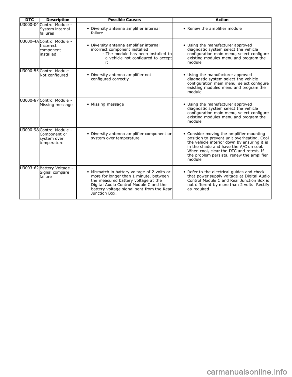
DTC Description Possible Causes Action U3000-04
Control Module -
System internal
failures
Diversity antenna amplifier internal
failure
Renew the amplifier module U3000-4A
Control Module -
Incorrect
component
installed
Diversity antenna amplifier internal
incorrect component installed
- The module has been installed to
a vehicle not configured to accept
it
Using the manufacturer approved
diagnostic system select the vehicle
configuration main menu, select configure
existing modules menu and program the
module U3000-55
Control Module -
Not configured
Diversity antenna amplifier not
configured correctly
Using the manufacturer approved
diagnostic system select the vehicle
configuration main menu, select configure
existing modules menu and program the
module U3000-87
Control Module -
Missing message
Missing message
Using the manufacturer approved
diagnostic system select the vehicle
configuration main menu, select configure
existing modules menu and program the
module U3000-98
Control Module -
Component or
system over
temperature
Diversity antenna amplifier component or
system over temperature
Consider moving the amplifier mounting
position to prevent unit overheating. Cool
the vehicle interior down by ensuring it is
in the shade and have the A/C on cool.
When cool, clear the DTC and retest. If
the problem persists, renew the amplifier
module U3003-62
Battery Voltage -
Signal compare
failure
Mismatch in battery voltage of 2 volts or
more for longer than 1 minute, between
the measured battery voltage at the
Digital Audio Control Module C and the
battery voltage signal sent from the Rear
Junction Box.
Refer to the electrical guides and check
that power supply voltage at Digital Audio
Control Module C and Rear Junction Box is
not different by more than 2 volts. Rectify
as required
Page 336 of 3039
Front Suspension - Front Shock Absorber
Removal and Installation Published: 09-Oct-2012
NOTES: Removal
Fuse box release only required on removal of the RH front shock absorber.
Expansion tank release only required for supercharged variant removal of the LH front shock absorber.
All vehicles
1. WARNING: Do not work on or under a vehicle supported only by a
jack. Always support the vehicle on safety stands.
Raise and support the vehicle.
2. Remove the front wheel and tire.
For additional information, refer to: Wheel and Tire (204-04 Wheels and Tires, Removal and Installation).
3. Remove the front stabilizer bar link.
For additional information, refer to: Front Stabilizer Bar Link (204-01 Front Suspension, Removal and Installation).
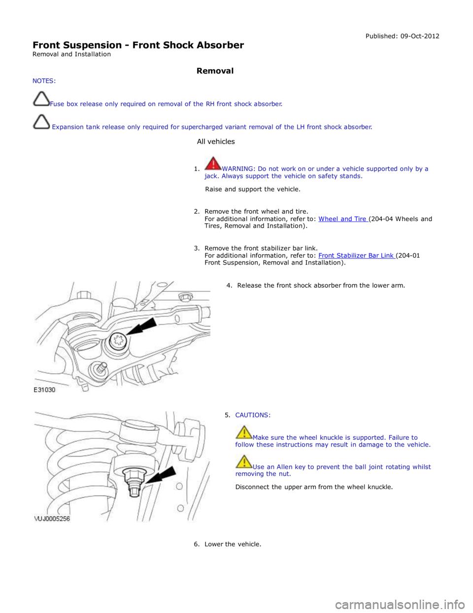
4. Release the front shock absorber from the lower arm.
5. CAUTIONS:
Make sure the wheel knuckle is supported. Failure to
follow these instructions may result in damage to the vehicle.
Use an Allen key to prevent the ball joint rotating whilst
removing the nut.
Disconnect the upper arm from the wheel knuckle.
6. Lower the vehicle.
Page 340 of 3039
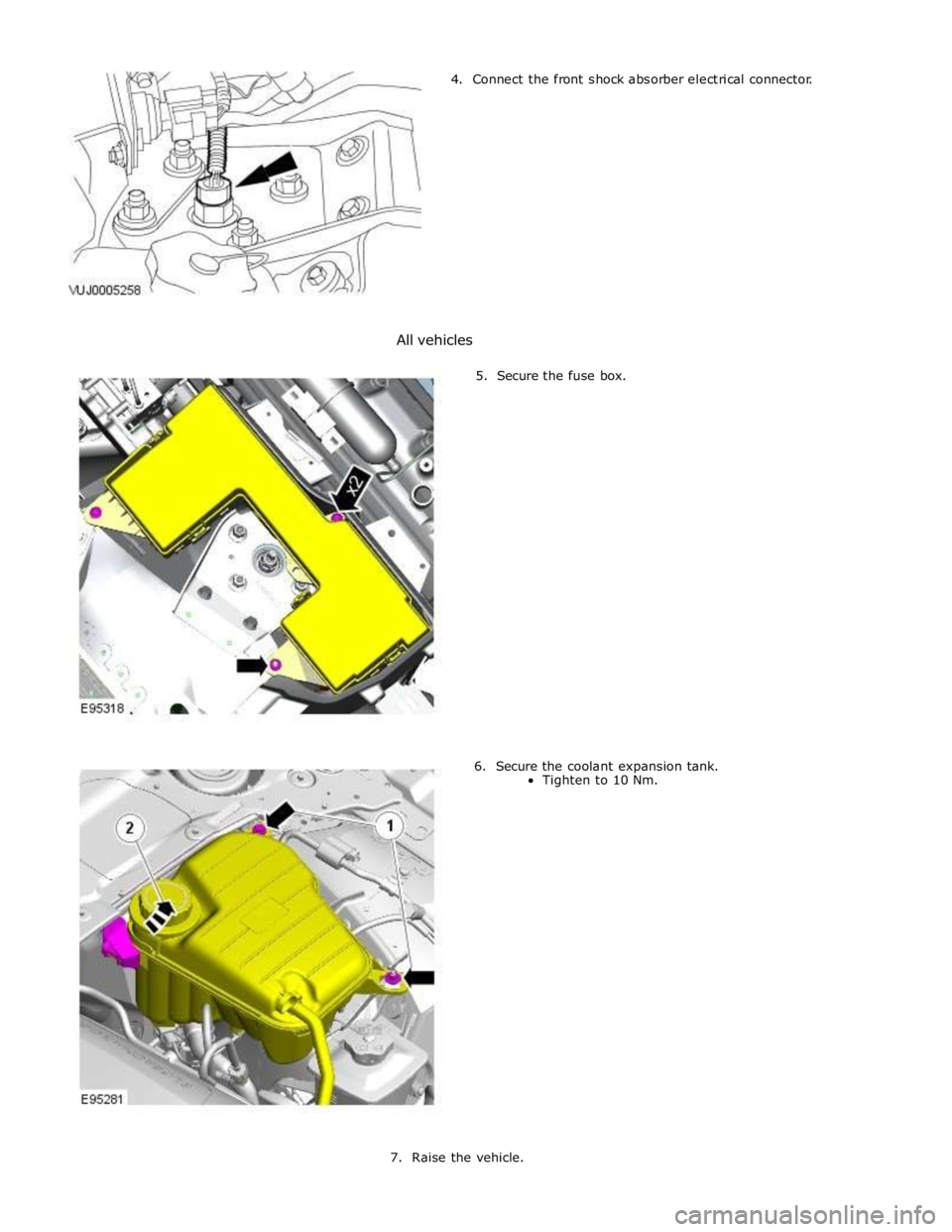
4. Connect the front shock absorber electrical connector.
All vehicles
5. Secure the fuse box.
6. Secure the coolant expansion tank.
Tighten to 10 Nm.
7. Raise the vehicle.
Page 442 of 3039
Published: 11-May-2011
Wheels and Tires - Wheels and Tires - System Operation and Component Description
Description and Operation
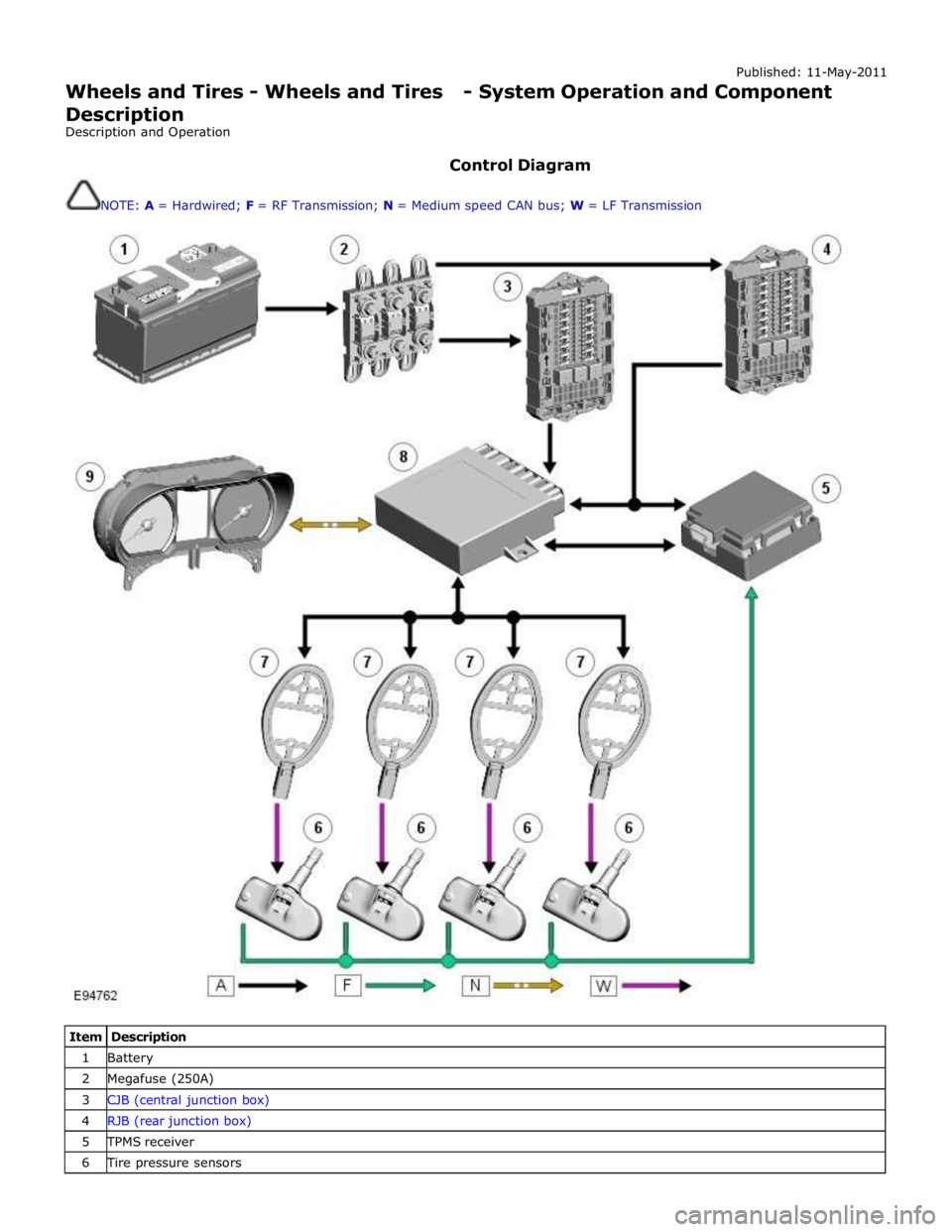
Control Diagram
NOTE: A = Hardwired; F = RF Transmission; N = Medium speed CAN bus; W = LF Transmission
Item Description 1 Battery 2 Megafuse (250A) 3 CJB (central junction box) 4 RJB (rear junction box) 5 TPMS receiver 6 Tire pressure sensors
Page 450 of 3039
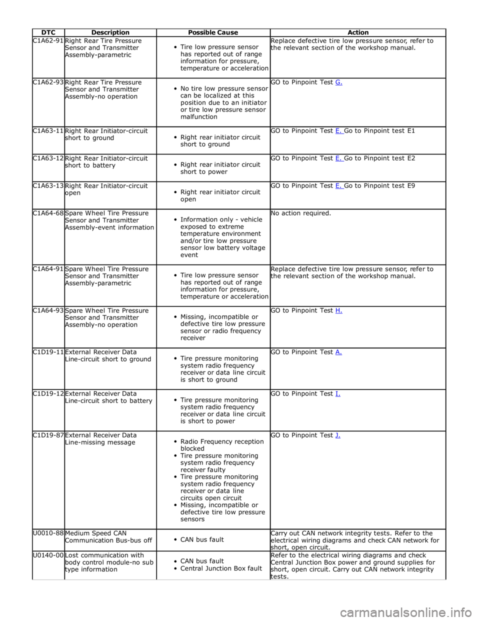
DTC Description Possible Cause Action C1A62-91
Right Rear Tire Pressure
Sensor and Transmitter
Assembly-parametric
Tire low pressure sensor
has reported out of range
information for pressure,
temperature or acceleration Replace defective tire low pressure sensor, refer to
the relevant section of the workshop manual. C1A62-93
Right Rear Tire Pressure
Sensor and Transmitter
Assembly-no operation
No tire low pressure sensor
can be localized at this
position due to an initiator
or tire low pressure sensor
malfunction GO to Pinpoint Test G. C1A63-11
Right Rear Initiator-circuit
short to ground
Right rear initiator circuit
short to ground GO to Pinpoint Test E. Go to Pinpoint test E1 C1A63-12
Right Rear Initiator-circuit
short to battery
Right rear initiator circuit
short to power GO to Pinpoint Test E. Go to Pinpoint test E2 C1A63-13
Right Rear Initiator-circuit
open
Right rear initiator circuit
open GO to Pinpoint Test E. Go to Pinpoint test E9 C1A64-68
Spare Wheel Tire Pressure
Sensor and Transmitter
Assembly-event information
Information only - vehicle
exposed to extreme
temperature environment
and/or tire low pressure
sensor low battery voltage
event No action required. C1A64-91
Spare Wheel Tire Pressure
Sensor and Transmitter
Assembly-parametric
Tire low pressure sensor
has reported out of range
information for pressure,
temperature or acceleration Replace defective tire low pressure sensor, refer to
the relevant section of the workshop manual. C1A64-93
Spare Wheel Tire Pressure
Sensor and Transmitter
Assembly-no operation
Missing, incompatible or
defective tire low pressure
sensor or radio frequency
receiver GO to Pinpoint Test H. C1D19-11
External Receiver Data
Line-circuit short to ground
Tire pressure monitoring
system radio frequency
receiver or data line circuit
is short to ground GO to Pinpoint Test A. C1D19-12
External Receiver Data
Line-circuit short to battery
Tire pressure monitoring
system radio frequency
receiver or data line circuit
is short to power GO to Pinpoint Test I. C1D19-87
External Receiver Data
Line-missing message
Radio Frequency reception
blocked
Tire pressure monitoring
system radio frequency
receiver faulty
Tire pressure monitoring
system radio frequency
receiver or data line
circuits open circuit
Missing, incompatible or
defective tire low pressure
sensors GO to Pinpoint Test J. U0010-88
Medium Speed CAN
Communication Bus-bus off
CAN bus fault Carry out CAN network integrity tests. Refer to the
electrical wiring diagrams and check CAN network for
short, open circuit. U0140-00
Lost communication with
body control module-no sub
type information
CAN bus fault
Central Junction Box fault Refer to the electrical wiring diagrams and check
Central Junction Box power and ground supplies for
short, open circuit. Carry out CAN network integrity
tests.
Page 451 of 3039
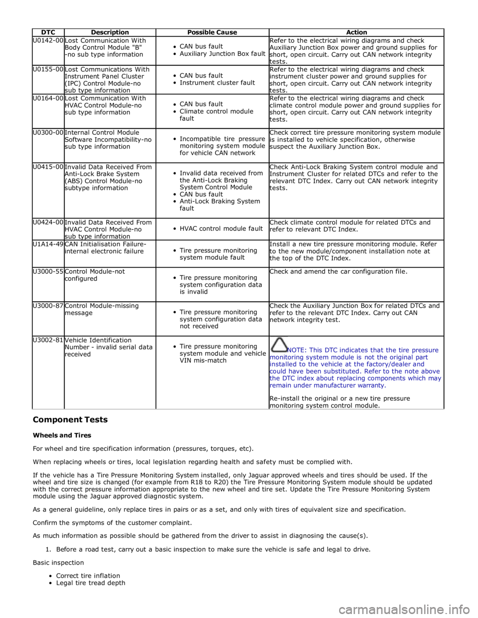
DTC Description Possible Cause Action U0142-00
Lost Communication With
Body Control Module "B"
-no sub type information
CAN bus fault
Auxiliary Junction Box fault Refer to the electrical wiring diagrams and check
Auxiliary Junction Box power and ground supplies for
short, open circuit. Carry out CAN network integrity
tests. U0155-00
Lost Communications With
Instrument Panel Cluster
(IPC) Control Module-no
sub type information
CAN bus fault
Instrument cluster fault Refer to the electrical wiring diagrams and check
instrument cluster power and ground supplies for
short, open circuit. Carry out CAN network integrity
tests. U0164-00
Lost Communication With
HVAC Control Module-no
sub type information
CAN bus fault
Climate control module
fault Refer to the electrical wiring diagrams and check
climate control module power and ground supplies for
short, open circuit. Carry out CAN network integrity
tests. U0300-00
Internal Control Module
Software Incompatibility-no
sub type information
Incompatible tire pressure
monitoring system module
for vehicle CAN network Check correct tire pressure monitoring system module
is installed to vehicle specification, otherwise
suspect the Auxiliary Junction Box. U0415-00
Invalid Data Received From
Anti-Lock Brake System
(ABS) Control Module-no
subtype information
Invalid data received from
the Anti-Lock Braking
System Control Module
CAN bus fault
Anti-Lock Braking System
fault Check Anti-Lock Braking System control module and
Instrument Cluster for related DTCs and refer to the
relevant DTC Index. Carry out CAN network integrity
tests. U0424-00
Invalid Data Received From
HVAC Control Module-no
sub type information
HVAC control module fault Check climate control module for related DTCs and
refer to relevant DTC Index. U1A14-49
CAN Initialisation Failure-
internal electronic failure
Tire pressure monitoring
system module fault Install a new tire pressure monitoring module. Refer
to the new module/component installation note at
the top of the DTC Index. U3000-55
Control Module-not
configured
Tire pressure monitoring
system configuration data
is invalid Check and amend the car configuration file. U3000-87
Control Module-missing
message
Tire pressure monitoring
system configuration data
not received Check the Auxiliary Junction Box for related DTCs and
refer to the relevant DTC Index. Carry out CAN
network integrity test. U3002-81
Vehicle Identification
Number - invalid serial data
received
Tire pressure monitoring
system module and vehicle
VIN mis-match
NOTE: This DTC indicates that the tire pressure
monitoring system module is not the original part
installed to the vehicle at the factory/dealer and
could have been substituted. Refer to the note above
the DTC index about replacing components which may
remain under manufacturer warranty.
Re-install the original or a new tire pressure monitoring system control module.
Component Tests
Wheels and Tires
For wheel and tire specification information (pressures, torques, etc).
When replacing wheels or tires, local legislation regarding health and safety must be complied with.
If the vehicle has a Tire Pressure Monitoring System installed, only Jaguar approved wheels and tires should be used. If the
wheel and tire size is changed (for example from R18 to R20) the Tire Pressure Monitoring System module should be updated
with the correct pressure information appropriate to the new wheel and tire set. Update the Tire Pressure Monitoring System
module using the Jaguar approved diagnostic system.
As a general guideline, only replace tires in pairs or as a set, and only with tires of equivalent size and specification.
Confirm the symptoms of the customer complaint.
As much information as possible should be gathered from the driver to assist in diagnosing the cause(s).
1. Before a road test, carry out a basic inspection to make sure the vehicle is safe and legal to drive.
Basic inspection
Correct tire inflation
Legal tire tread depth
Page 482 of 3039
Published: 11-May-2011
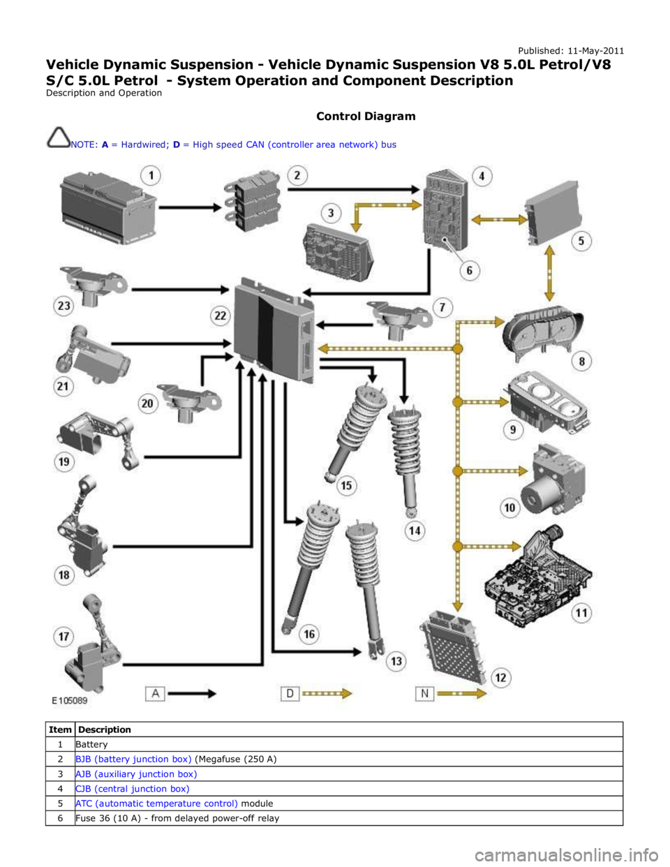
Vehicle Dynamic Suspension - Vehicle Dynamic Suspension V8 5.0L Petrol/V8 S/C 5.0L Petrol - System Operation and Component Description
Description and Operation
Control Diagram
NOTE: A = Hardwired; D = High speed CAN (controller area network) bus
Item Description 1 Battery 2 BJB (battery junction box) (Megafuse (250 A) 3 AJB (auxiliary junction box) 4 CJB (central junction box) 5 ATC (automatic temperature control) module 6 Fuse 36 (10 A) - from delayed power-off relay