box JAGUAR XFR 2010 1.G User Guide
[x] Cancel search | Manufacturer: JAGUAR, Model Year: 2010, Model line: XFR, Model: JAGUAR XFR 2010 1.GPages: 3039, PDF Size: 58.49 MB
Page 138 of 3039

DTC Description Possible Causes Action B10F9-93
Accessory socket 'B'
relay - No operation
Front powerpoint, trailer tow
connector, road pricing
connector, sunblind power
supply circuits - short to
power, ground, open circuit
Carry out any pinpoint tests associated with this
DTC using the manufacturer approved diagnostic
system. Refer to the electrical circuit diagrams
and check front powerpoint, trailer tow connector,
road pricing connector, sunblind power supply
circuits for short to power, ground, open circuit B10FA-93
Delayed Power Off
relay - No operation
ADRC ECM, roof header
console lamp, glove box
lamp , RH/LH footwell
lamps, JAG Sense glove box
module, RH/LH sunvisor
lamps, rear dome lamps
switched power circuits -
short to power, open circuit
Carry out any pinpoint tests associated with this
DTC using the manufacturer approved diagnostic
system. Refer to the electrical circuit diagrams
and check ADRC ECM, roof header console lamp,
glove box lamp , RH/LH footwell lamps, JAG
Sense glove box module, RH/LH sunvisor lamps,
rear dome lamps switched power circuits for short
to power, open circuit B10FF-11
Ignition control -
Circuit short to ground
ECM and FPDB ignition
control circuit - short to
ground
Carry out any pinpoint tests associated with this
DTC using the manufacturer approved diagnostic
system. Refer to the electrical circuit diagrams
and check ECM and FPDB ignition control circuit
for short to ground B10FF-13
Ignition control -
Circuit open
ECM and FPDB ignition
control circuit - open circuit
Carry out any pinpoint tests associated with this
DTC using the manufacturer approved diagnostic
system. Refer to the electrical circuit diagrams
and check ECM and FPDB ignition control circuit
for open circuit B1100-11 O2 sensor heater relay
- Circuit short to
ground
FPDB O2 sensor heater relay
control circuit - short to
ground
Carry out any pinpoint tests associated with this
DTC using the manufacturer approved diagnostic
system. Refer to the electrical circuit diagrams
and check FPDB O2 sensor heater relay control
circuit for short to ground B113D-12
Sunroof Global
Open/Close Control -
Circuit short to battery
Roof opening panel global
open/close control circuit -
short to power
Carry out any pinpoint tests associated with this
DTC using the manufacturer approved diagnostic
system. Refer to the electrical circuit diagrams
and check roof opening panel global open/close
control circuit for short to power B113D-14
Sunroof Global
Open/Close Control -
Circuit short to ground
or open
Roof opening panel global
open/close control circuit -
short to ground, open circuit
Refer to the electrical circuit diagrams and check
roof opening panel global open/close control
circuit for short to ground, open circuit B1140-11
Engine Crank
Authorisation - Circuit
short to ground
Engine crank authorisation
signal circuit - short to
ground
Carry out any pinpoint tests associated with this
DTC using the manufacturer approved diagnostic
system. Refer to the electrical circuit diagrams
and check engine crank authorisation signal circuit
for short to ground B1142-11
Ignition Status 1 -
Circuit short to ground
Ignition supply 1 circuits -
short to ground
Carry out any pinpoint tests associated with this
DTC using the manufacturer approved diagnostic
system. Refer to the electrical circuit diagrams
and check all ignition supply 1 circuits for short to
ground B1143-11
Ignition Status 2 -
Circuit short to ground
Ignition supply 2 circuits -
short to ground
Carry out any pinpoint tests associated with this
DTC using the manufacturer approved diagnostic
system. Refer to the electrical circuit diagrams
and check all ignition supply 2 circuits for short to
ground B1144-11
Heated Steering
Wheel Supply - Circuit
short to ground
Heated steering wheel
supply circuit - short to
ground
Carry out any pinpoint tests associated with this
DTC using the manufacturer approved diagnostic
system. Refer to the electrical circuit diagrams
and check heated steering wheel supply circuit for
short to ground
Page 139 of 3039

DTC Description Possible Causes Action B1145-11
Glovebox Locking
Motor - Circuit short to
ground
Glovebox latch locking motor
circuit - short to ground
Carry out any pinpoint tests associated with this
DTC using the manufacturer approved diagnostic
system. Refer to the electrical circuit diagrams
and check glovebox latch locking motor circuit for
short to ground B1145-12
Glovebox Locking
Motor - Circuit short to
battery
Glovebox latch locking motor
control circuit - short to
power
Refer to the electrical circuit diagrams and check
glovebox latch locking motor control circuit for
short to power B1145-13
Glovebox Locking
Motor - Circuit open
Glovebox latch locking motor
control circuit - open circuit
Refer to the electrical circuit diagrams and check
glovebox latch locking motor control circuit for
open circuit B1146-12
Passive sounder
Supply - Circuit short
to battery
Security passive sounder
control circuit - short to
power
Refer to the electrical circuit diagrams and check
security passive sounder control circuit for short
to power B1146-14
Passive sounder
Supply - Circuit short
to ground or open
Security passive sounder
control circuit - short to
ground, open circuit
Refer to the electrical circuit diagrams and check
security passive sounder control circuit for short
to ground, open circuit B1158-11
Front Passenger Seat
Heater Sensor - Circuit
short to ground
Front passenger seat heater
sensor circuit - short to
ground
Carry out any pinpoint tests associated with this
DTC using the manufacturer approved diagnostic
system. Refer to the electrical circuit diagrams
and check front passenger seat heater sensor
circuit for short to ground B1158-13
Front Passenger Seat
Heater Sensor - Circuit
open
Front passenger seat heater
sensor circuit - open circuit
Carry out any pinpoint tests associated with this
DTC using the manufacturer approved diagnostic
system. Refer to the electrical circuit diagrams
and check front passenger seat heater sensor
circuit for open circuit B1159-11
Driver Seat Heater
Sensor - Circuit short
to ground
Driver seat heater sensor
circuit - short to ground
Carry out any pinpoint tests associated with this
DTC using the manufacturer approved diagnostic
system. Refer to the electrical circuit diagrams
and check driver seat heater sensor circuit for
short to ground B1159-13
Driver Seat Heater
Sensor - Circuit open
Driver seat heater sensor
circuit - open circuit
Carry out any pinpoint tests associated with this
DTC using the manufacturer approved diagnostic
system. Refer to the electrical circuit diagrams
and check driver seat heater sensor circuit for
open circuit B115A-11
Front Passenger Seat
Heater - Circuit short
to ground
Front passenger seat heater
supply circuit - short to
ground
Carry out any pinpoint tests associated with this
DTC using the manufacturer approved diagnostic
system. Refer to the electrical circuit diagrams
and check front passenger seat heater supply
circuit for short to ground B115A-15
Front Passenger Seat
Heater - Circuit short
to battery or open
Front passenger seat heater
supply circuit - short to
power, open circuit
Carry out any pinpoint tests associated with this
DTC using the manufacturer approved diagnostic
system. Refer to the electrical circuit diagrams
and check front passenger seat heater supply
circuit for short to power, open circuit B115B-11
Driver Seat Heater -
Circuit short to ground
Driver seat heater supply
circuit - short to ground
Carry out any pinpoint tests associated with this
DTC using the manufacturer approved diagnostic
system. Refer to the electrical circuit diagrams
and check driver seat heater supply circuit for
short to ground
Page 161 of 3039
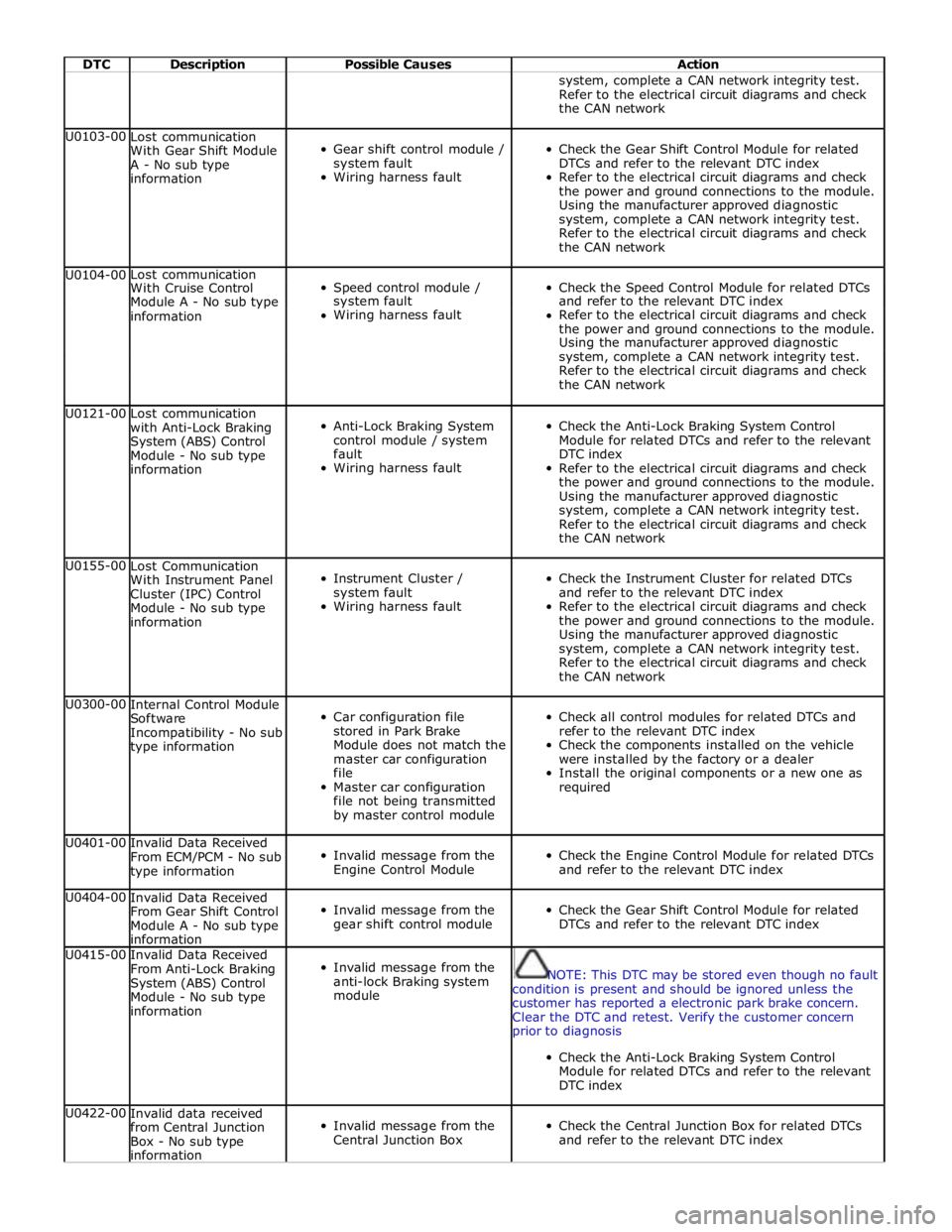
DTC Description Possible Causes Action system, complete a CAN network integrity test.
Refer to the electrical circuit diagrams and check
the CAN network U0103-00
Lost communication
With Gear Shift Module
A - No sub type
information
Gear shift control module /
system fault
Wiring harness fault
Check the Gear Shift Control Module for related
DTCs and refer to the relevant DTC index
Refer to the electrical circuit diagrams and check
the power and ground connections to the module.
Using the manufacturer approved diagnostic
system, complete a CAN network integrity test.
Refer to the electrical circuit diagrams and check
the CAN network U0104-00 Lost communication
Speed control module /
Check the Speed Control Module for related DTCs With Cruise Control Module A - No sub type system fault and refer to the relevant DTC index information Wiring harness fault Refer to the electrical circuit diagrams and check the power and ground connections to the module. Using the manufacturer approved diagnostic system, complete a CAN network integrity test. Refer to the electrical circuit diagrams and check the CAN network U0121-00
Lost communication
with Anti-Lock Braking
System (ABS) Control
Module - No sub type
information
Anti-Lock Braking System
control module / system
fault
Wiring harness fault
Check the Anti-Lock Braking System Control
Module for related DTCs and refer to the relevant
DTC index
Refer to the electrical circuit diagrams and check
the power and ground connections to the module.
Using the manufacturer approved diagnostic
system, complete a CAN network integrity test.
Refer to the electrical circuit diagrams and check
the CAN network U0155-00
Lost Communication
With Instrument Panel
Cluster (IPC) Control
Module - No sub type
information
Instrument Cluster /
system fault
Wiring harness fault
Check the Instrument Cluster for related DTCs
and refer to the relevant DTC index
Refer to the electrical circuit diagrams and check
the power and ground connections to the module.
Using the manufacturer approved diagnostic
system, complete a CAN network integrity test.
Refer to the electrical circuit diagrams and check
the CAN network U0300-00
Internal Control Module
Software
Incompatibility - No sub
type information
Car configuration file
stored in Park Brake
Module does not match the
master car configuration
file
Master car configuration
file not being transmitted
by master control module
Check all control modules for related DTCs and
refer to the relevant DTC index
Check the components installed on the vehicle
were installed by the factory or a dealer
Install the original components or a new one as
required U0401-00
Invalid Data Received
From ECM/PCM - No sub
type information
Invalid message from the
Engine Control Module
Check the Engine Control Module for related DTCs
and refer to the relevant DTC index U0404-00
Invalid Data Received
From Gear Shift Control
Module A - No sub type
information
Invalid message from the
gear shift control module
Check the Gear Shift Control Module for related
DTCs and refer to the relevant DTC index U0415-00
Invalid Data Received
From Anti-Lock Braking
System (ABS) Control
Module - No sub type
information
Invalid message from the
anti-lock Braking system
module
NOTE: This DTC may be stored even though no fault
condition is present and should be ignored unless the
customer has reported a electronic park brake concern.
Clear the DTC and retest. Verify the customer concern
prior to diagnosis
Check the Anti-Lock Braking System Control
Module for related DTCs and refer to the relevant
DTC index U0422-00
Invalid data received
from Central Junction
Box - No sub type
information
Invalid message from the
Central Junction Box
Check the Central Junction Box for related DTCs
and refer to the relevant DTC index
Page 165 of 3039

DTC Description Possible Causes Action module/component B10AC-82 Cruise Control Switch - Alive / sequence counter incorrect / not updated
Cruise buttons alive counter is not
incrementing. Which suggests that
the LIN bus is faulty
Steering wheel module is not
connected
Steering wheel module failure
Refer to the electrical circuit
diagrams and check the speed
control switch circuit for open circuit,
short circuit to power, short circuit to
ground, disconnected
Refer to the electrical circuit
diagrams and check the LIN bus
between steering wheel module and
the CAN gateway
Check and install a new steering
wheel module as required. Refer to
the warranty policy and procedures
manual, or determine if any prior
approval programme is in operation,
prior to the installation of a new
module/component B10AC-83
Cruise Control Switch - Value
of signal protection
calculation incorrect
Cruise buttons checksum incorrect,
incorrect cruise switches fitted to
vehicle
Check and install new cruise
switches as required. Refer to the
warranty policy and procedures
manual, or determine if any prior
approval programme is in operation,
prior to the installation of a new
module/component B10AC-96
Cruise Control Switch -
Component internal failure
Speed control switch circuit, open
circuit, short circuit to power, short
circuit to ground, disconnected
Speed control switch failure
Steering wheel module failure
Check for related DTCs in other
central junction boxes
Refer to the electrical circuit
diagrams and check the speed
control switch circuit for open circuit,
short circuit to power, short circuit to
ground, disconnected
Check and install a new speed
control switch as required. Check and
install a new steering wheel module
as required. Refer to the warranty
policy and procedures manual, or
determine if any prior approval
programme is in operation, prior to
the installation of a new
module/component B10FF-68
Ignition Control - Event
information
Spark plug(s) fault
Wiring harness fault
Ignition coil(s) fault
Refer to repair manual and check
spark plug(s) for condition and
security. Replace any defective
components as required
Refer to electrical wiring diagrams
and check ignition coil circuit for
intermittent open circuit, short
circuit to power, short circuit to
ground
Check and install a new coil(s) as
required. Refer to the warranty policy
and procedures manual, or determine
if any prior approval programme is in
operation, prior to the installation of
a new module/component B11DB-01
Battery Monitoring Module -
General electrical failure
NOTE: - Circuit BATTERY -
Charging system fault Battery
monitoring signal line
circuit fault
Vehicle battery fault
Refer to electrical wiring diagrams
and check charging system for faults.
Perform any repairs required
Refer to the electrical wiring
diagrams and check the battery
monitoring system module circuit for
open circuit, short circuit to ground,
short circuit to power
Refer to the workshop manual and
the battery care manual, inspect the
vehicle battery and ensure it is fully
charged and serviceable before
performing further tests
Page 181 of 3039

DTC Description Possible Causes Action B1231-7A
Right Seat - Fluid leak
or seal failure
Seat backrest assembly -
Air path leaking
Seat cushion assembly -
Air path leaking
Seat assembly damaged
Check for blockage or restriction in seat
backrest/seat cushion thermal electric device fan
ducts
Check seat backrest/seat cushion thermal electric
device fan exhaust vent is clear
Carry out on demand self test using manufacturer
approved diagnostic system to confirm
rectification. Alternatively, carry out any pinpoint
tests associated with this DTC using the
manufacturer approved diagnostic system B1232-7A
Left Seat - Fluid leak or
seal failure
Seat backrest assembly -
Air path leaking
Seat cushion assembly -
Air path leaking
Seat assembly damaged
Check for blockage or restriction in seat
backrest/seat cushion thermal electric device fan
ducts
Check seat backrest/seat cushion thermal electric
device fan exhaust vent is clear
Carry out on demand self test using manufacturer
approved diagnostic system to confirm
rectification. Alternatively, carry out any pinpoint
tests associated with this DTC using the
manufacturer approved diagnostic system B1235-13
Left Seat Cushion Temperature Sensor -
Circuit open
Connectors disconnected or
connector pin damage
Seat cushion temperature
sensor left circuit - Open
circuit
Front seat climate control
module failure
Check for any disconnected connectors or damaged
connector pins
Carry out on demand self test using manufacturer
approved diagnostic system to confirm the fault is
present
Refer to the electrical circuit diagrams and check
the front seat climate control module - Circuit
reference LH_CUSHION_SENSOR, Circuit reference
LH_CUSHION_SENSOR_RTN - For open circuit.
Repair circuit as required, clear DTC and retest
Carry out on demand self test using manufacturer
approved diagnostic system to confirm
rectification. Alternatively, carry out any pinpoint
tests associated with this DTC using the
manufacturer approved diagnostic system U0010-88
Medium Speed CAN
Communication Bus -
Bus off
Medium speed CAN
communication - Bus off
Refer to the electrical circuit diagrams and check
the power and ground connections to the module
Using the manufacturer approved diagnostic
system, complete a CAN network integrity test
Carry out on demand self test using manufacturer
approved diagnostic system to confirm rectification U0140-00
Lost Communication
With Body Control
Module - No sub type
information
Lost communication with
central junction box
NOTE: This DTC may be stored even though no fault
condition is present and should be ignored unless the
customer has reported a climate seat concern. Clear the
DTC and retest. Verify the customer concern prior to
diagnosis
Refer to the electrical circuit diagrams and check
the power and ground connections to the module
Using the manufacturer approved diagnostic
system, complete a CAN network integrity test
Refer to the electrical circuit diagrams and check
the CAN network between the front seat climate
control module and central junction box
Carry out on demand self test using manufacturer
approved diagnostic system to confirm rectification U0142-00 Lost Communication
Lost communication with
Refer to the electrical circuit diagrams and check With Body Control Module "B" - No sub rear junction box the power and ground connections to the module type information Using the manufacturer approved diagnostic system, complete a CAN network integrity test Refer to the electrical circuit diagrams and check the CAN network between the front seat climate control module and rear junction box Carry out on demand self test using manufacturer approved diagnostic system to confirm rectification www.JagDocs.com
Page 182 of 3039

DTC Description Possible Causes Action U0155-00
Lost Communication
With Instrument Panel
Cluster (IPC) Control
Module - No sub type
information
Lost communication with
instrument cluster
Refer to the electrical circuit diagrams and check
the power and ground connections to the module
Using the manufacturer approved diagnostic
system, complete a CAN network integrity test
Refer to the electrical circuit diagrams and check
the CAN network between the front seat climate
control module and instrument cluster
Carry out on demand self test using manufacturer
approved diagnostic system to confirm rectification U0156-00 Lost Communication
Lost communication with
Refer to the electrical circuit diagrams and check With Information Center "A" - No sub rear seat entertainment the power and ground connections to the module type information control module Using the manufacturer approved diagnostic system, complete a CAN network integrity test Refer to the electrical circuit diagrams and check the CAN network between the front seat climate control module and rear seat entertainment control module Carry out on demand self test using manufacturer approved diagnostic system to confirm rectification U0300-00
Internal Control Module
Software
Incompatibility - No
sub type information
Software stored in front
seat climate control
module is not compatible
with master configuration
Check the front seat climate control module is
configured correctly
Reconfigure the front seat climate control module
using the manufacturer approved diagnostic
system. Clear the DTC and retest the system
Carry out on demand self test using manufacturer
approved diagnostic system to confirm rectification U0401-00
Invalid Data Received
From ECM/PCM - No
sub type information
The engine control module
has transmitted engine
speed quality factor CAN
signal at a specific value
for a greater than expected
time period
Check the engine control module for related DTCs
and refer to the relevant DTC index
On software levels previous to 8X23-14B663-AE
clear the DTC and take no further action if the
system is operating correctly U2101-00 Control module
Compatible central car
Using the manufacturer approved diagnostic Configuration Incompatible - No sub configuration file not system check and update the car configuration file type information received by front seat as required. Carry out on demand self test using climate control module manufacturer approved diagnostic system to confirm rectification. Clear the DTC and retest U3000-04
Control Module -
System internal
failures
Front seat climate control
module - Internal failure
Check and install new front seat climate control
module as required. Carry out on demand self test
using manufacturer approved diagnostic system to
confirm rectification U3003-62
Battery Voltage -
Signal compare failure
Wiring harness fault
Battery internal failure
Charging system fault
Refer to the electrical circuit diagrams and check
the power and ground connections to the front
seat climate control module and the central
junction box
Refer to the battery care manual and verify that
the vehicle battery is fully charged and serviceable
before continuing with further diagnostic tests
Check the vehicle charging system
Page 185 of 3039
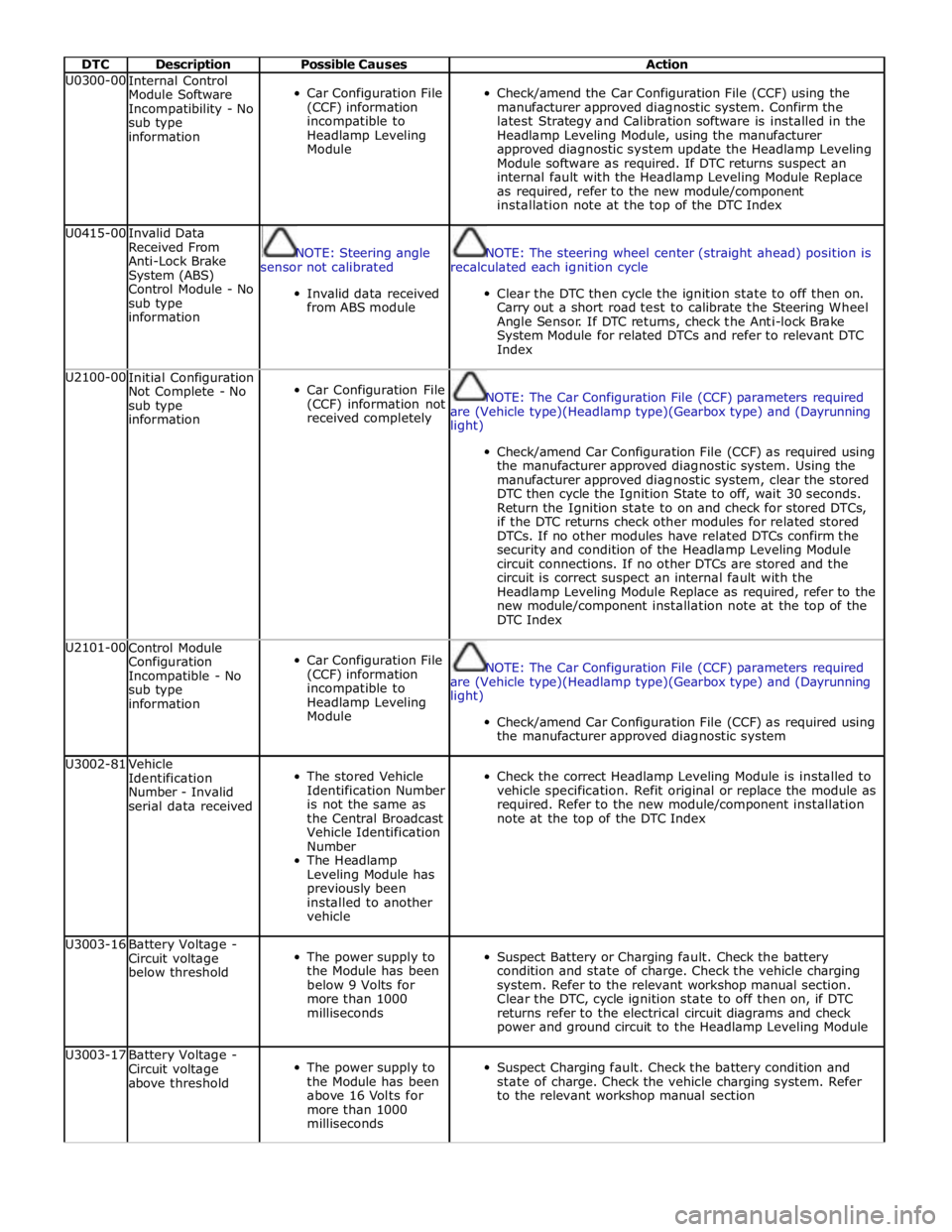
DTC Description Possible Causes Action U0300-00
Internal Control
Module Software
Incompatibility - No
sub type
information
Car Configuration File
(CCF) information
incompatible to
Headlamp Leveling
Module
Check/amend the Car Configuration File (CCF) using the
manufacturer approved diagnostic system. Confirm the
latest Strategy and Calibration software is installed in the
Headlamp Leveling Module, using the manufacturer
approved diagnostic system update the Headlamp Leveling
Module software as required. If DTC returns suspect an
internal fault with the Headlamp Leveling Module Replace
as required, refer to the new module/component
installation note at the top of the DTC Index U0415-00
Invalid Data
Received From
Anti-Lock Brake
System (ABS)
Control Module - No
sub type
information
NOTE: Steering angle
sensor not calibrated
Invalid data received
from ABS module
NOTE: The steering wheel center (straight ahead) position is
recalculated each ignition cycle
Clear the DTC then cycle the ignition state to off then on.
Carry out a short road test to calibrate the Steering Wheel
Angle Sensor. If DTC returns, check the Anti-lock Brake
System Module for related DTCs and refer to relevant DTC
Index U2100-00
Initial Configuration
Not Complete - No
sub type
information
Car Configuration File
(CCF) information not
received completely
NOTE: The Car Configuration File (CCF) parameters required
are (Vehicle type)(Headlamp type)(Gearbox type) and (Dayrunning
light)
Check/amend Car Configuration File (CCF) as required using
the manufacturer approved diagnostic system. Using the
manufacturer approved diagnostic system, clear the stored
DTC then cycle the Ignition State to off, wait 30 seconds.
Return the Ignition state to on and check for stored DTCs,
if the DTC returns check other modules for related stored
DTCs. If no other modules have related DTCs confirm the
security and condition of the Headlamp Leveling Module
circuit connections. If no other DTCs are stored and the
circuit is correct suspect an internal fault with the
Headlamp Leveling Module Replace as required, refer to the
new module/component installation note at the top of the
DTC Index U2101-00
Control Module
Configuration
Incompatible - No
sub type
information
Car Configuration File
(CCF) information
incompatible to
Headlamp Leveling
Module
NOTE: The Car Configuration File (CCF) parameters required
are (Vehicle type)(Headlamp type)(Gearbox type) and (Dayrunning
light)
Check/amend Car Configuration File (CCF) as required using
the manufacturer approved diagnostic system U3002-81
Vehicle
Identification
Number - Invalid
serial data received
The stored Vehicle
Identification Number
is not the same as
the Central Broadcast
Vehicle Identification
Number
The Headlamp
Leveling Module has
previously been
installed to another
vehicle
Check the correct Headlamp Leveling Module is installed to
vehicle specification. Refit original or replace the module as
required. Refer to the new module/component installation
note at the top of the DTC Index U3003-16
Battery Voltage -
Circuit voltage
below threshold
The power supply to
the Module has been
below 9 Volts for
more than 1000
milliseconds
Suspect Battery or Charging fault. Check the battery
condition and state of charge. Check the vehicle charging
system. Refer to the relevant workshop manual section.
Clear the DTC, cycle ignition state to off then on, if DTC
returns refer to the electrical circuit diagrams and check
power and ground circuit to the Headlamp Leveling Module U3003-17
Battery Voltage -
Circuit voltage
above threshold
The power supply to
the Module has been
above 16 Volts for
more than 1000
milliseconds
Suspect Charging fault. Check the battery condition and
state of charge. Check the vehicle charging system. Refer
to the relevant workshop manual section
Page 186 of 3039

DTC Description Possible Causes Action U3003-62
Battery Voltage -
Signal compare
failure
Difference in battery
voltage, of 2 volts or
more, between the
central broadcast
voltage (via CAN Bus)
and Headlamp
Leveling Module
Check other modules for related stored DTCs. Refer to the
electrical circuit diagrams and check power and ground
voltages at the Headlamp Leveling Module U0428-00
Invalid Data
Received From
Steering Angle
Sensor Module - No
sub type
information
NOTE: Steering Angle
Sensor not calibrated
Invalid Data Received
from the Steering
Angle Sensor Module
Check the Steering Angle Sensor Module for stored DTCs.
Using the manufacturer approved diagnostic system,
complete the CAN Network Integrity test. Refer to the
electrical circuit diagrams and check the CAN network
between the Headlamp Leveling Module and the
Transmission Control Module U0402-00
Invalid Data
Received From
Transmission
Control Module - No
sub type
information
Invalid Data Received
from the
Transmission Control
Module
Transmission
component fault
Check the Transmission Control Module for stored DTCs.
Using the manufacturer approved diagnostic system,
complete the CAN Network Integrity test. Refer to the
electrical circuit diagrams and check the CAN network
between the Headlamp Leveling Module and the
Transmission Control Module U0126-00
Lost Communication
With Steering Angle
Sensor Module - No
sub type
information
Lost communication
with the Steering
Angle Sensor Module
CAN network fault
Check the Steering Angle Sensor Module for stored DTCs.
Using the manufacturer approved diagnostic system,
complete the CAN Network Integrity test. Refer to the
electrical circuit diagrams and check the CAN network
between the Headlamp Leveling Module and the Steering
Angle Sensor U0142-00 Lost Communication
Lost communication
Check the Auxiliary Junction Box for stored DTCs. Using the With Body Control Module "B" - No sub with the Auxiliary manufacturer approved diagnostic system, complete the type information Junction Box CAN Network Integrity test. Refer to the electrical circuit CAN network fault diagrams and check the CAN network between the Headlamp Leveling Module and the Auxiliary Junction Box www.JagDocs.com
Page 189 of 3039

DTC Description Possible Causes Action B100B-87
Column Lock Ground
Authorisation - Missing
message
Instrument cluster power
and ground supply circuits -
short, open circuit
LS CAN fault
RJB power and ground
supply circuits - short, open
circuit
Carry out any pinpoint tests associated with this
DTC using the manufacturer approved diagnostic
system. Refer to the electrical circuit diagrams
and check RJB power and ground supply circuits
for short, open circuit and instrument cluster
power and ground supply circuits for short, open
circuit. Check CAN communications between RJB
and instrument cluster B100C-67
Column Lock Supply
Authorisation - Signal
incorrect after event
Instrument cluster power
and ground supply circuits -
short, open circuit
LS CAN fault
CJB power and ground
supply circuits - short, open
circuit
Vehicle speed present when
attempting to power ESCL
Engine speed present when
attempting to power ESCL
PowerMode status > 4 when
attempting to perform lock
action
Carry out any pinpoint tests associated with this
DTC using the manufacturer approved diagnostic
system. Refer to the electrical circuit diagrams
and check CJB power and ground supply circuits
for short, open circuit and instrument cluster
power and ground supply circuits for short, open
circuit. Check CAN communications between CJB
and instrument cluster. Check for invalid vehicle
speed signal from ABS/instrument cluster
gateway. Check for invalid engine speed signal
from ECM/instrument cluster gateway. Check for
invalid signal from CJB B100C-87
Column Lock Supply
Authorisation - Missing
message
Instrument cluster power
and ground supply circuits -
short, open circuit
LS CAN fault
CJB power and ground
supply circuits - short, open
circuit
Carry out any pinpoint tests associated with this
DTC using the manufacturer approved diagnostic
system. Refer to the electrical circuit diagrams
and check CJB power and ground supply circuits
for short, open circuit and instrument cluster
power and ground supply circuits for short, open
circuit. Check CAN communications between CJB
and instrument cluster B100D-62
Column Lock
Authorisation - Signal
compare failure
CAN fault
ESCL power and ground
supply circuits - short, open
circuit
Instrument cluster power
and ground supply circuits -
short, open circuit
Incorrect ESCL or instrument
cluster installed
Target SID synchronization
error following
re-programming
Noise/EMC related error
Carry out any pinpoint tests associated with this
DTC using the manufacturer approved diagnostic
system. Check CAN communication between
Electronic Steering Column Lock and instrument
cluster. Refer to the electrical circuit diagrams
and check Electronic Steering Column Lock power
and ground supply circuits for short, open circuit
and Instrument cluster power and ground supply
circuits for short, open circuit. Check correct
Electronic Steering Column Lock and instrument
cluster installed. Perform the Immobilisation
application from the Set-up menu using the
manufacturer approved diagnostic system. Check
CAN network for interference/EMC related issues B100D-64
Column Lock
Authorisation - Signal
plausibility failure
Algorithm based failure-
signal plausibility failure
CAN fault
ESCL power and ground
supply circuits - short, open
circuit
Instrument cluster power
and ground supply circuits -
short, open circuit
If the customer has not reported a non start
issue, clear the DTC and check vehicle starts
correctly. If a non start issue has been reported
run the manufacturers approved diagnostic
system Start Authorisation Application and
follow the actions required for this DTC. Carry
out any pinpoint tests associated with this DTC
using the manufacturer approved diagnostic
system. Check CAN communication between
Electronic Steering Column Lock and instrument
cluster (check transmission out speed, vehicle
speed, engine speed, gear position and
powermode signals to Electronic Steering
Column Lock). Refer to the electrical circuit
diagrams and check Electronic Steering Column
Lock power and ground supply circuits for short,
open circuit and Instrument cluster power and
ground supply circuits for short, open circuit B100D-87
Column Lock
Authorisation - Missing
message - Missing
message
Missing message
CAN fault
No response from electric
steering column lock control
module, instrument cluster,
central junction box
Clear DTC, repeatedly lock and unlock car using
the key fob and retest. Check for related DTCs
and refer to the relevant DTC index
If the fault is cleared, notify the customer that
the steering column lock may fail to unlock if the
vehicle is parked with a high steering angle or
Page 190 of 3039

DTC Description Possible Causes Action Battery voltage at electric
steering column lock control
module too low
Electric steering column lock
control module, instrument
cluster, central junction box
fault with the road wheel against a curb. If the
column lock is failing to disengage, the customer
may be able to rectify this by rotating the
steering wheel while pressing the engine start
button
If fault persists, complete a CAN network
integrity test using the manufacturers approved
diagnostic system. Alternatively, refer to the
electrical circuit diagrams and check CAN circuits
between the central junction box, the instrument
cluster and the electronic steering column lock.
Refer to the electrical circuit diagrams and check
the central junction box, the instrument cluster
and the electronic steering column lock power
and ground supply circuits for short circuit to
ground, short circuit to power, open circuit, high
resistance. Repair circuit(s) as required. Clear
DTC, perform an on demand self-test and retest
If fault persists, check that the vehicle battery
supply voltage is between 9-16 volts. Rectify as
required B100D-96
Column Lock
Authorisation -
Component internal
failure
Battery voltage at electric
steering column lock control
module too low
Torque load on steering
column
CAN fault
Electric steering column lock
control module - Internal
failure
Clear DTC, repeatedly lock and unlock car using
the key fob and retest
If fault persists, check that the vehicle battery
supply voltage is between 9-16 volts. Rectify as
required
Ensure the column lock bolt movement is not
obstructed or restricted (the parked position of
the road wheels may be exerting a turning force
through the steering column, preventing the lock
from releasing. The steering wheel may need to
be held against the force to allow the column
lock to release). Clear DTC, repeatedly lock and
unlock car using the key fob and retest
If fault persists, complete a CAN network
integrity test using the manufacturers approved
diagnostic system. Alternatively, refer to the
electrical circuit diagrams and check CAN circuits
between the central junction box, the instrument
cluster and the electronic steering column lock.
Refer to the electrical circuit diagrams and check
the central junction box, the instrument cluster
and the electronic steering column lock power
and ground supply circuits for short circuit to
ground, short circuit to power, open circuit, high
resistance. Repair circuit(s) as required. Clear
DTC, perform an on demand self-test and retest
If fault persists, check and install a new electric
steering column lock control module as required B1024-87
Start Control Unit -
Missing message
Smart card docking station
failure - slave node not
responding
Carry out any pinpoint tests associated with this
DTC using the manufacturer approved diagnostic
system. Refer to the electrical circuit diagrams
and check the smart card docking station LIN
circuit for short, open circuit. Suspect the smart
card docking station, check and install a new
docking station as required, refer to the new
module/component installation note at the top
of the DTC Index B1046-11
Front Fog Lamp Control
Switch - Circuit short to
ground
Fog lamp switch circuit -
short to ground
Refer to the electrical circuit diagrams and check
fog lamp switch circuit for short to ground B1046-15
Front Fog Lamp Control
Switch - Circuit short to
battery or open
Fog lamp switch circuit -
short to power, open circuit
Refer to the electrical circuit diagrams and check
fog lamp switch circuit for short to power, open
circuit B1048-11 Brake Fluid Level Switch
- Circuit short to ground
Brake fluid level switch
circuit - short to ground
Refer to the electrical circuit diagrams and check
brake fluid level switch circuit for short to ground