box JAGUAR XFR 2010 1.G Owner's Manual
[x] Cancel search | Manufacturer: JAGUAR, Model Year: 2010, Model line: XFR, Model: JAGUAR XFR 2010 1.GPages: 3039, PDF Size: 58.49 MB
Page 204 of 3039

DTC Description Possible Causes Action B1A54-11
Occupant Belt Tension Sensor -
Circuit short to
ground
Safety belt tension
sensor voltage reference
or signal circuit - short
to ground
Refer to the electrical circuit diagrams and check safety
belt tension sensor voltage reference and signal circuits
for short to ground B1A54-12
Occupant Belt Tension Sensor -
Circuit short to
battery
Safety belt tension
sensor voltage reference
or signal circuit - short
to power
Refer to the electrical circuit diagrams and check safety
belt tension sensor voltage reference and signal circuits
for short to power B1A54-13
Occupant Belt Tension Sensor -
Circuit open
Safety belt tension
sensor voltage reference
or signal circuit - open
circuit
Refer to the electrical circuit diagrams and check safety
belt tension sensor voltage reference and signal circuits
for open circuit B1A62-02
Pressure Sensor -
General signal
failure
General signal failure
Refer to the electrical circuit diagrams and check safety
belt tension and mat pressure sensor circuits for short to
each other B1A62-11
Pressure Sensor -
Circuit short to
ground
Mat pressure sensor
voltage reference or
signal circuits - short to
ground
Refer to the electrical circuit diagrams and check mat
pressure sensor voltage reference and signal circuits for
short to ground B1A62-12
Pressure Sensor -
Circuit short to
battery
Mat pressure sensor
voltage reference,
ground or signal circuits
- short to power
Refer to the electrical circuit diagrams and check mat
pressure sensor voltage reference, ground and signal
circuits for short to power B1A62-13
Pressure Sensor -
Circuit open
Mat pressure sensor
voltage reference or
signal circuit - open
circuit
Refer to the electrical circuit diagrams and check mat
pressure sensor voltage reference and signal circuits for
open circuit B1A62-7B
Pressure Sensor -
Low fluid level
Low fluid level - bladder
damaged
Check and install new bladder as required. Refer to the
warranty policy and procedures manual, or determine if
any prior approval programme is in operation, prior to the
installation of a new module/component U0001-88
High Speed CAN
Communication
Bus - Bus off
Bus off
Refer to the electrical circuit diagrams and check CAN
network for short, open circuit. Carry out the CAN
network integrity test using the manufacturer approved
diagnostic system U0151-00
Lost
Communication
With Restraints
Control Module -
No sub type
information
Restraints control
module missing
message
Refer to the electrical circuit diagrams and check power
and ground supplies to restraints control module. Carry
out CAN network integrity test using the manufacturer
approved diagnostic system U0300-00
Internal Control
Module Software
Incompatibility -
No sub type
information
Master car configuration
file ID does not
correspond
Check correct occupancy seat module is installed for
vehicle specification. Check rear junction box for related
diagnostic trouble codes and refer to relevant diagnostic
trouble code index U2016-51
Control Module
Main Software -
Not programmed
Main software not
programmed
Check and install a new occupancy seat module as
required. Refer to the warranty policy and procedures
manual, or determine if any prior approval programme is
in operation, prior to the installation of a new
module/component U201A-51
Control Module
Main Calibration
Data - Not
programmed
Main calibration data not
programmed
Check and install a new occupancy seat module as
required. Refer to the warranty policy and procedures
manual, or determine if any prior approval programme is
in operation, prior to the installation of a new
module/component
Page 212 of 3039

DTC Description Possible Causes Action Cycle the ignition off, then on, to power up parking
aid system and check corrective action B1B58-11
Rear Sensors Power
Circuit - Circuit short
to ground
Wiring harness fault
Control Module -
Component internal
failure
Check rear and front (if front PDC fitted) bumper
harness for signs of damage and security of
connections
Refer to electrical wiring diagrams and check the
parking assist rear sensor power circuit and front
sensor power circuit (if front PDC fitted) for short
circuit to ground. Repair or replace any wiring harness
as required
Using the manufacturers approved diagnostic system
clear the DTC and run the on demand self test. If the
problem persists, suspect the control module
Cycle the ignition off, then on, to power up parking
aid system and check corrective action B1C30-73
Disable Switch -
Actuator stuck closed
Wiring harness fault
Control Switch -
Component internal
failure
Refer to electrical wiring diagrams and check the
parking assist switch and switch circuit. Repair or
replace any wiring harness as required
Using the manufacturers approved diagnostic system
clear the DTC and run the on demand self test. If the
problem persists, suspect the control switch
Check the switch function U0010-00
Medium Speed CAN
Communication Bus -
No sub type
information
Medium speed CAN
failure - bus off
Refer to the electrical circuit diagrams and check the
parking aid control module medium speed CAN bus
for short circuit to ground, short circuit to power,
open circuit, high resistance, or short circuit between
the paired CAN wires
Using the manufacturer approved diagnostic system,
complete a CAN network integrity test
Cycle the ignition off, then on, and check if the DTC
is still logged U0073-00
Control Module
Communication Bus
"A" Off - No sub type
information
Control module
communication Bus "A"
failure - bus off
Refer to the electrical circuit diagrams and check the
parking aid control module high speed CAN bus for
short circuit to ground, short circuit to power, open
circuit, high resistance, or short circuit between the
paired CAN wires
Using the manufacturer approved diagnostic system,
complete a CAN network integrity test
Cycle the ignition off, then on, and check if the DTC
is still logged U0140-00
Lost Communication
With Body Control
Module - No sub type
information
Loss of CAN
communication with
central junction box
Refer to the electrical circuit diagrams and check the
power and ground connections to the central junction
box. Clear DTC and retest
Using the manufacturer approved diagnostic system,
complete a CAN network integrity test. Refer to the
electrical circuit diagrams and check the CAN network
between the central junction box and the parking aid
control module U0142-00 Lost Communication
Loss of CAN
Refer to the electrical circuit diagrams and check the With Body Control Module "B" - No sub communication with power and ground connections to the auxiliary type information auxiliary junction box junction box. Clear DTC and retest Using the manufacturer approved diagnostic system, complete a CAN network integrity test. Refer to the electrical circuit diagrams and check the CAN network between the central junction box and the parking aid control module U0155-00
Lost Communication
With Instrument Panel
Cluster (IPC) Control
Module - No sub type
information
Loss of CAN
communication with
instrument cluster
Refer to the electrical circuit diagrams and check the
power and ground connections to the instrument
cluster. Clear DTC and retest
Using the manufacturer approved diagnostic system,
complete a CAN network integrity test. Refer to the
electrical circuit diagrams and check the CAN network
between the central junction box and the parking aid
control module
Page 213 of 3039
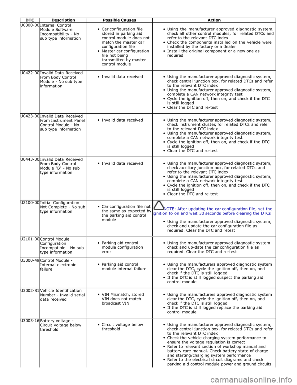
DTC Description Possible Causes Action U0300-00
Internal Control
Module Software
Incompatibility - No
sub type information
Car configuration file
stored in parking aid
control module does not
match the master car
configuration file
Master car configuration
file not being
transmitted by master
control module
Using the manufacturer approved diagnostic system,
check all other control modules, for related DTCs and
refer to the relevant DTC index
Check the components installed on the vehicle were
installed by the factory or a dealer
Install the original component or a new one as
required U0422-00
Invalid Data Received
From Body Control
Module - No sub type
information
Invalid data received
Using the manufacturer approved diagnostic system,
check central junction box, for related DTCs and refer
to the relevant DTC index
Using the manufacturer approved diagnostic system,
complete a CAN network integrity test
Cycle the ignition off, then on, and check if the DTC
is still logged
Clear the DTC and re-test U0423-00
Invalid Data Received
From Instrument Panel
Control Module - No
sub type information
Invalid data received
Using the manufacturer approved diagnostic system,
check instrument cluster, for related DTCs and refer
to the relevant DTC index
Using the manufacturer approved diagnostic system,
complete a CAN network integrity test
Cycle the ignition off, then on, and check if the DTC
is still logged
Clear the DTC and re-test U0443-00
Invalid Data Received
From Body Control
Module "B" - No sub
type information
Invalid data received
Using the manufacturer approved diagnostic system,
check auxiliary junction box, for related DTCs and
refer to the relevant DTC index
Using the manufacturer approved diagnostic system,
complete a CAN network integrity test
Cycle the ignition off, then on, and check if the DTC
is still logged
Clear the DTC and re-test U2100-00
Initial Configuration
Not Complete - No sub
type information
Car configuration file not
the same as expected by
the parking aid control
module
NOTE: After updating the car configuration file, set the
ignition to on and wait 30 seconds before clearing the DTCs
Using the manufacturer approved diagnostic system,
check and update the car configuration file as
required. Clear the DTC and retest U2101-00
Control Module
Configuration
Incompatible - No sub
type information
Parking aid control
module configuration
error
Using the manufacturer approved diagnostic system
check and up-date the car configuration file as
required. Clear the DTC and re-test U3000-49
Control Module -
Internal electronic
failure
Parking aid control
module internal failure
Using the manufacturers approved diagnostic system
clear the DTC, cycle the ignition off, then on, and
check if the DTC is still logged
If the DTC is still logged suspect the parking aid
control module U3002-81
Vehicle Identification
Number - Invalid serial
data received
VIN Mismatch, stored
VIN does not match
broadcast VIN
Using the manufacturers approved diagnostic system
clear the DTC, cycle the ignition off, then on, and
check if the DTC is still logged
If the DTC is still logged replace the parking aid
control module U3003-16
Battery voltage -
Circuit voltage below
threshold
Circuit voltage below
threshold
Using the manufacturer approved diagnostic system,
check central junction box, for related DTCs and refer
to the relevant DTC index
Check the vehicle charging system performance to
ensure the voltage regulation is correct
Refer to relevant section of workshop manual and
battery care manual. Check battery state of charge
and starting/charging system performance
Refer to the electrical circuit diagrams and check
parking aid control module power and ground circuits
Page 214 of 3039

DTC Description Possible Causes Action for short circuit to ground, short circuit to power,
open circuit
Clear the DTC and retest U3003-17
Battery Voltage -
Circuit voltage above
threshold
Circuit voltage above
threshold
Using the manufacturer approved diagnostic system,
check central junction box, for related DTCs and refer
to the relevant DTC index
Check the vehicle charging system performance to
ensure the voltage regulation is correct
Refer to relevant section of workshop manual and
battery care manual. Check battery state of charge
and starting/charging system performance
Refer to the electrical circuit diagrams and check
parking aid control module power and ground circuits
for short circuit to ground, short circuit to power,
open circuit
Clear the DTC and retest U3003-62
Battery Voltage -
Signal compare failure
Signal compare failure in
battery voltage, of 2
volts or more, between
parking aid control
module and central
junction box
Using the manufacturer approved diagnostic system,
check central junction box, for related DTCs and refer
to the relevant DTC index
Check the vehicle charging system performance to
ensure the voltage regulation is correct
Refer to relevant section of workshop manual and
battery care manual. Check battery state of charge
and starting/charging system performance
Refer to the electrical circuit diagrams and check
parking aid control module power and ground circuits
for short circuit to ground, short circuit to power,
open circuit
Clear the DTC and retest
Page 218 of 3039
Published: 12-May-2014
General Information - Diagnostic Trouble Code (DTC) Index DTC: Rear
Junction Box (RJB)
Description and Operation
Rear Junction Box (RJB)
CAUTION: Diagnosis by substitution from a donor vehicle is NOT acceptable. Substitution of control modules does not
guarantee confirmation of a fault, and may also cause additional faults in the vehicle being tested and/or the donor vehicle.
NOTES:
If a control module or a component is suspect and the vehicle remains under manufacturer warranty, refer to the Warranty
Policy and Procedures manual, or determine if any prior approval programme is in operation, prior to the installation of a new
module/component.
Generic scan tools may not read the codes listed, or may read only 5-digit codes. Match the 5 digits from the scan tool to
the first 5 digits of the 7-digit code listed to identify the fault (the last 2 digits give extra information read by the
manufacturer-approved diagnostic system).
When performing voltage or resistance tests, always use a digital multimeter accurate to three decimal places, and with
an up-to-date calibration certificate. When testing resistance always take the resistance of the digital multimeter leads into
account.
Check and rectify basic faults before beginning diagnostic routines involving pinpoint tests.
Inspect connectors for signs of water ingress, and pins for damage and/or corrosion.
If DTCs are recorded and, after performing the pinpoint tests, a fault is not present, an intermittent concern may be the
cause. Always check for loose connections and corroded terminals.
Check DDW for open campaigns. Refer to the corresponding bulletins and SSMs which may be valid for the specific
customer complaint and carry out the recommendations as required.
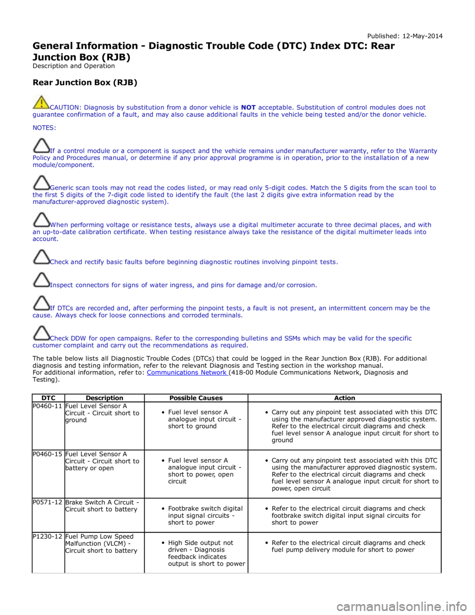
The table below lists all Diagnostic Trouble Codes (DTCs) that could be logged in the Rear Junction Box (RJB). For additional
diagnosis and testing information, refer to the relevant Diagnosis and Testing section in the workshop manual.
For additional information, refer to: Communications Network (418-00 Module Communications Network, Diagnosis and Testing).
DTC Description Possible Causes Action P0460-11
Fuel Level Sensor A
Circuit - Circuit short to
ground
Fuel level sensor A
analogue input circuit -
short to ground
Carry out any pinpoint test associated with this DTC
using the manufacturer approved diagnostic system.
Refer to the electrical circuit diagrams and check
fuel level sensor A analogue input circuit for short to
ground P0460-15
Fuel Level Sensor A
Circuit - Circuit short to
battery or open
Fuel level sensor A
analogue input circuit -
short to power, open
circuit
Carry out any pinpoint test associated with this DTC
using the manufacturer approved diagnostic system.
Refer to the electrical circuit diagrams and check
fuel level sensor A analogue input circuit for short to
power, open circuit P0571-12
Brake Switch A Circuit -
Circuit short to battery
Footbrake switch digital
input signal circuits -
short to power
Refer to the electrical circuit diagrams and check
footbrake switch digital input signal circuits for
short to power P1230-12
Fuel Pump Low Speed
Malfunction (VLCM) -
Circuit short to battery
High Side output not
driven - Diagnosis
feedback indicates
output is short to power
Refer to the electrical circuit diagrams and check
fuel pump delivery module for short to power
Page 237 of 3039

DTC Description Possible Causes Action B1A89-12
Satellite Antenna -
Circuit short to
battery
Satellite antenna circuit -
short to power
Refer to the electrical circuit diagrams and check
satellite antenna circuit for short circuit to power. Repair
wiring harness as required. Clear DTC and retest B1A89-13
Satellite Antenna -
Circuit open
Satellite antenna circuit -
open circuit, high
resistance
Refer to the electrical circuit diagrams and check
satellite antenna circuit for open circuit, high
resistance. Repair wiring harness as required. Clear DTC
and retest U3000-04
Control Module -
System internal
failures
System internal failure
Check and install a new satellite radio module as
required. Refer to the warranty policy and procedures
manual, or determine if any prior approval programme is
in operation, prior to the installation of a new
module/component U3000-4A Control Module -
Satellite radio module -
Using the manufacturer approved diagnostic system Incorrect component Incorrect component select the vehicle configuration main menu>vehicle installed installed configuration>display and modify the vehicle Car configuration configuration file data mismatch Check update as required U3000-55
Control Module -
Not configured
Satellite radio module -
Incorrect component
installed
Incorrect car configuration
file data received
Using the manufacturer approved diagnostic system
select the vehicle configuration main menu>select
configure existing modules menu and program the
satellite radio module U3000-87
Control Module -
Missing message
The satellite radio module
has not received the
configuration file
Master module not
transmitting configuration
file
Using the manufacturer approved diagnostic system
check that the satellite radio module is configured
correctly
Check that the configuration file is being transmitted by
the master module
Using the manufacturer approved diagnostic system,
complete a MOST network integrity test U3000-98
Control Module -
Component or
system over
temperature
Satellite radio module
cooling vents obstructed
Wiring harness fault
Internal electronic failure
Check for possible causes of the satellite radio module
overheating. Check that the ventilation is not
obstructed
Check for short circuit related DTCs. Refer to the
electrical circuit diagrams and check ground circuit for
high resistance. Check antenna circuit for short to power
or ground. Repair wiring harness as required. Clear DTC
and retest
Check for internal electronic failure related DTCs
If fault persists, check and install a new satellite radio
module. Refer to the warranty policy and procedures
manual, or determine if any prior approval programme is
in operation, prior to the installation of a new
module/component U3003-62
Battery Voltage -
Signal compare
failure
Signal compare failure
Satellite radio module
voltage differs more than
±2V compared to rear
junction box voltage
Refer to relevant section of workshop manual and
battery care manual. Check battery state of charge and
starting/charging system performance. Check power
supply circuit from rear junction box to satellite radio
module
Refer to electrical circuit diagrams and check the power
and ground supply circuits to the module. Repair wiring
harness as required. Clear DTC and retest
Page 242 of 3039
Published: 17-Apr-2014
General Information - Diagnostic Trouble Code (DTC) Index DTC: Steering
Column Lock Module (VIM)
Description and Operation
Steering Column Lock Module (VIM)
CAUTION: Diagnosis by substitution from a donor vehicle is NOT acceptable. Substitution of control modules does not
guarantee confirmation of a fault and may also cause additional faults in the vehicle being checked and/or the donor vehicle.
NOTES:
If the control module or a component is suspect and the vehicle remains under manufacturer warranty, refer to the
Warranty Policy and Procedures manual, or determine if any prior approval programme is in operation, prior to the installation
of a new module/component.
Generic scan tools may not read the codes listed, or may read only 5-digit codes. Match the 5 digits from the scan tool to
the first 5 digits of the 7-digit code listed to identify the fault (the last 2 digits give extra information read by the
manufacturer approved diagnostic system).
When performing voltage or resistance tests, always use a digital multimeter (DMM) accurate to three decimal places,
and with an up-to-date calibration certificate. When testing resistance, always take the resistance of the DMM leads into
account.
Check and rectify basic faults before beginning diagnostic routines involving pinpoint tests.
If DTCs are recorded and, after performing the pinpoint tests a fault is not present, an intermittent concern may be the
cause. Always check for loose connections and corroded terminals.
Where an 'on demand self-test' is referred to, this can be accessed via the 'DTC Monitor' tab on the manufacturers
approved diagnostic system.
Check DDW for open campaigns. Refer to the corresponding bulletins and SSMs which may be valid for the specific
customer complaint and carry out the recommendations as required.
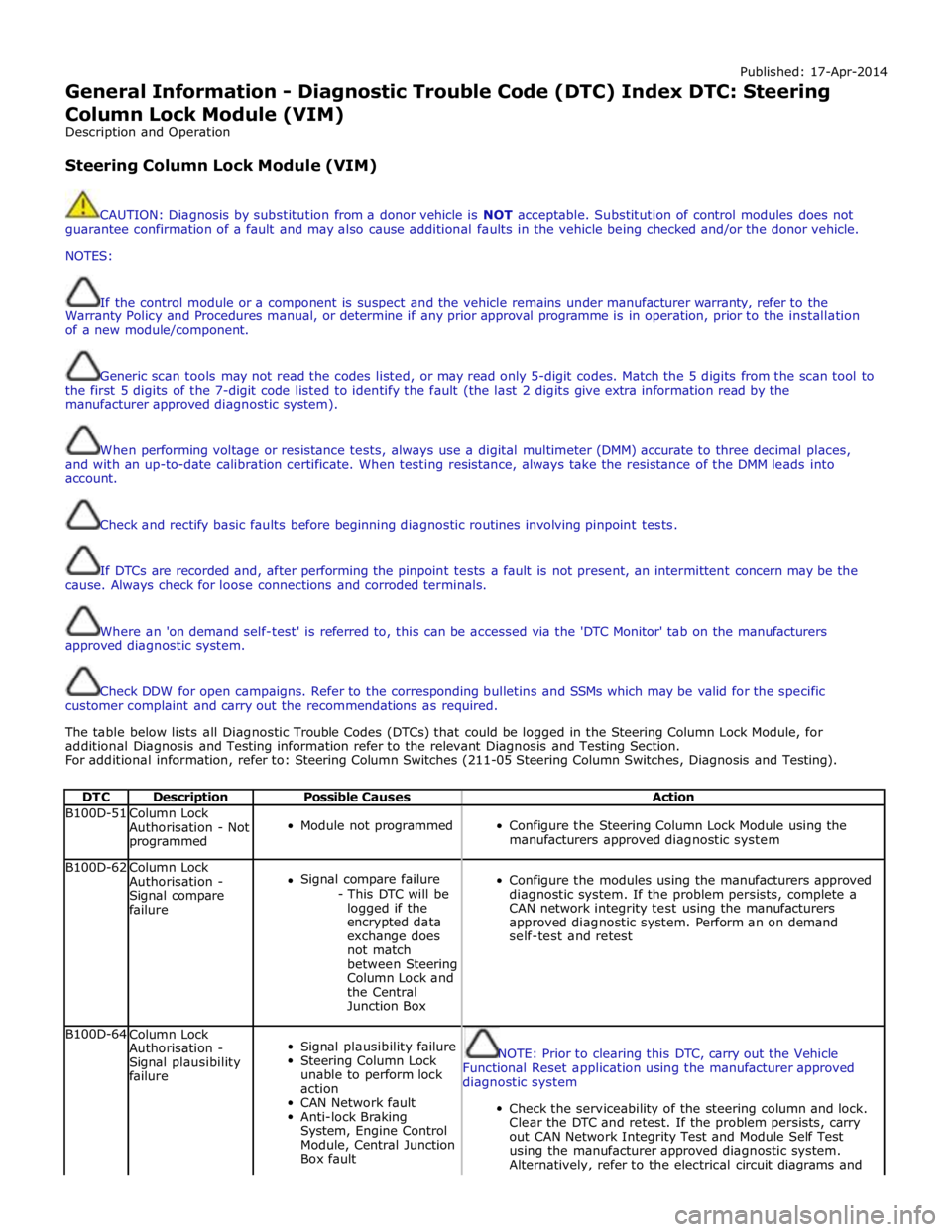
The table below lists all Diagnostic Trouble Codes (DTCs) that could be logged in the Steering Column Lock Module, for
additional Diagnosis and Testing information refer to the relevant Diagnosis and Testing Section.
For additional information, refer to: Steering Column Switches (211-05 Steering Column Switches, Diagnosis and Testing).
DTC Description Possible Causes Action B100D-51
Column Lock
Authorisation - Not
programmed
Module not programmed
Configure the Steering Column Lock Module using the
manufacturers approved diagnostic system B100D-62
Column Lock
Authorisation -
Signal compare
failure
Signal compare failure
- This DTC will be
logged if the
encrypted data
exchange does
not match
between Steering
Column Lock and
the Central
Junction Box
Configure the modules using the manufacturers approved
diagnostic system. If the problem persists, complete a
CAN network integrity test using the manufacturers
approved diagnostic system. Perform an on demand
self-test and retest B100D-64
Column Lock
Authorisation -
Signal plausibility
failure
Signal plausibility failure
Steering Column Lock
unable to perform lock
action
CAN Network fault
Anti-lock Braking
System, Engine Control
Module, Central Junction
Box fault
NOTE: Prior to clearing this DTC, carry out the Vehicle
Functional Reset application using the manufacturer approved
diagnostic system
Check the serviceability of the steering column and lock.
Clear the DTC and retest. If the problem persists, carry
out CAN Network Integrity Test and Module Self Test
using the manufacturer approved diagnostic system.
Alternatively, refer to the electrical circuit diagrams and
Page 243 of 3039
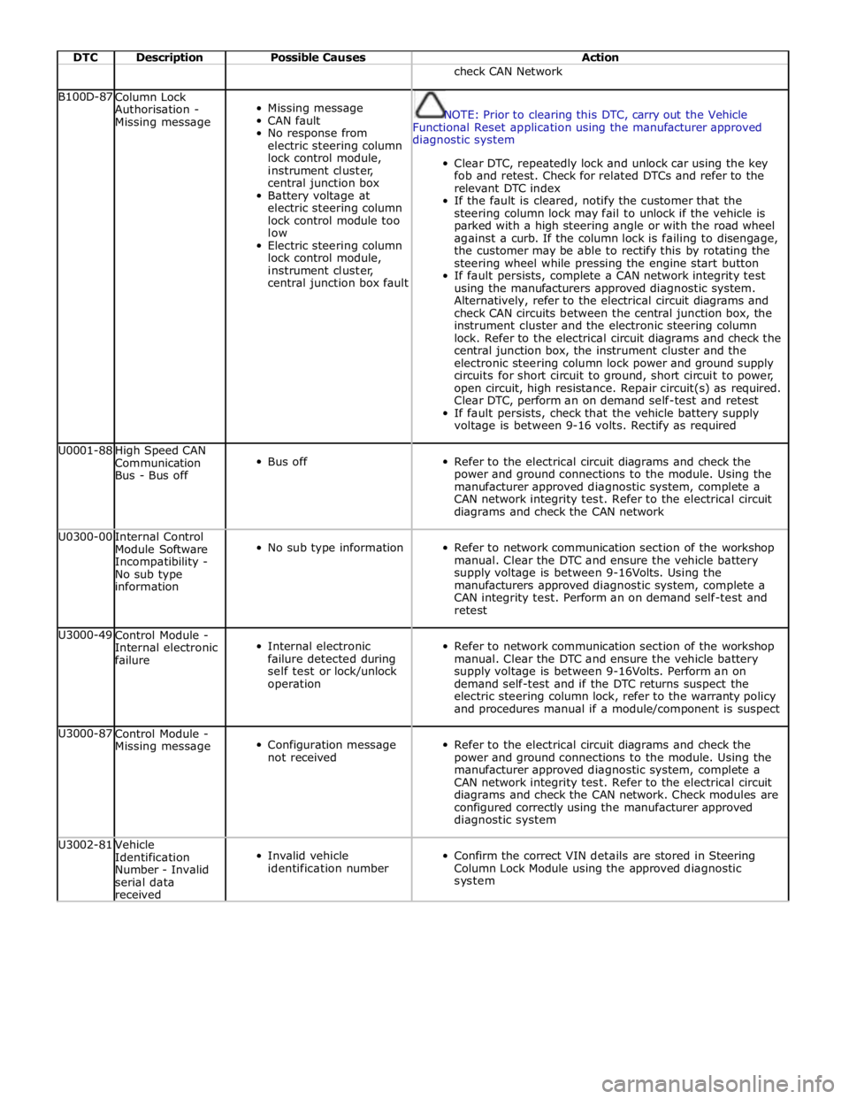
DTC Description Possible Causes Action check CAN Network B100D-87
Column Lock
Authorisation -
Missing message
Missing message
CAN fault
No response from
electric steering column
lock control module,
instrument cluster,
central junction box
Battery voltage at
electric steering column
lock control module too
low
Electric steering column
lock control module,
instrument cluster,
central junction box fault
NOTE: Prior to clearing this DTC, carry out the Vehicle
Functional Reset application using the manufacturer approved
diagnostic system
Clear DTC, repeatedly lock and unlock car using the key
fob and retest. Check for related DTCs and refer to the
relevant DTC index
If the fault is cleared, notify the customer that the
steering column lock may fail to unlock if the vehicle is
parked with a high steering angle or with the road wheel
against a curb. If the column lock is failing to disengage,
the customer may be able to rectify this by rotating the
steering wheel while pressing the engine start button
If fault persists, complete a CAN network integrity test
using the manufacturers approved diagnostic system.
Alternatively, refer to the electrical circuit diagrams and
check CAN circuits between the central junction box, the
instrument cluster and the electronic steering column
lock. Refer to the electrical circuit diagrams and check the
central junction box, the instrument cluster and the
electronic steering column lock power and ground supply
circuits for short circuit to ground, short circuit to power,
open circuit, high resistance. Repair circuit(s) as required.
Clear DTC, perform an on demand self-test and retest
If fault persists, check that the vehicle battery supply
voltage is between 9-16 volts. Rectify as required U0001-88
High Speed CAN
Communication
Bus - Bus off
Bus off
Refer to the electrical circuit diagrams and check the
power and ground connections to the module. Using the
manufacturer approved diagnostic system, complete a
CAN network integrity test. Refer to the electrical circuit
diagrams and check the CAN network U0300-00
Internal Control
Module Software
Incompatibility -
No sub type
information
No sub type information
Refer to network communication section of the workshop
manual. Clear the DTC and ensure the vehicle battery
supply voltage is between 9-16Volts. Using the
manufacturers approved diagnostic system, complete a
CAN integrity test. Perform an on demand self-test and
retest U3000-49
Control Module -
Internal electronic
failure
Internal electronic
failure detected during
self test or lock/unlock
operation
Refer to network communication section of the workshop
manual. Clear the DTC and ensure the vehicle battery
supply voltage is between 9-16Volts. Perform an on
demand self-test and if the DTC returns suspect the
electric steering column lock, refer to the warranty policy
and procedures manual if a module/component is suspect U3000-87
Control Module -
Missing message
Configuration message
not received
Refer to the electrical circuit diagrams and check the
power and ground connections to the module. Using the
manufacturer approved diagnostic system, complete a
CAN network integrity test. Refer to the electrical circuit
diagrams and check the CAN network. Check modules are
configured correctly using the manufacturer approved
diagnostic system U3002-81
Vehicle
Identification
Number - Invalid
serial data
received
Invalid vehicle
identification number
Confirm the correct VIN details are stored in Steering
Column Lock Module using the approved diagnostic
system
Page 249 of 3039

DTC Description Possible Causes Action C1A64-68
Spare Wheel Tire
Pressure Sensor and Transmitter Assembly -
Event information
Information only - vehicle
exposed to extreme
temperature environment
and/or tire pressure
sensor low battery
voltage event
No action required C1A64-91
Spare Wheel Tire
Pressure Sensor and Transmitter Assembly -
Parametric
Tire pressure sensor has
reported out of range
information for pressure,
temperature or
acceleration
Replace defective tire pressure sensor, refer to
the relevant section of the workshop manual C1A64-93
Spare Wheel Tire
Pressure Sensor and Transmitter Assembly -
No operation
Missing, incompatible or
defective tire pressure
sensor or radio frequency
receiver
For additional information, refer to: Wheels and
Tires (204-04 Wheels and Tires, Diagnosis and
Testing).Go to pinpoint test H in section 204-04,
Diagnosis and Testing, Wheels and Tires C1D19-11
External Receiver Data
Line - Circuit short to
ground
Tire pressure monitoring
system radio frequency
receiver or data line
circuit is short to ground
For additional information, refer to: Wheels and
Tires (204-04 Wheels and Tires, Diagnosis and
Testing).Go to pinpoint test A in section
204-04,Diagnosis and Testing, Wheels and Tires C1D19-12
External Receiver Data
Line - Circuit short to
battery
Tire pressure monitoring
system radio frequency
receiver or data line
circuit is short to power
For additional information, refer to: Wheels and
Tires (204-04 Wheels and Tires, Diagnosis and
Testing).Go to pinpoint test I in section 204-04,
diagnosis and testing C1D19-87
External Receiver Data
Line - Missing message
Radio Frequency
reception blocked
Tire pressure monitoring
system radio frequency
receiver faulty
Tire pressure monitoring
system radio frequency
receiver or data line
circuits open circuit
Missing, incompatible or
defective tire pressure
sensors
For additional information, refer to: Wheels and
Tires (204-04 Wheels and Tires, Diagnosis and
Testing).Go to pinpoint test J in section 204-04,
Diagnosis and Testing, Wheels and Tires U0010-88
Medium Speed CAN
Communication Bus - Bus
off
CAN bus fault
Carry out CAN network integrity tests. Refer to
the electrical wiring diagrams and check CAN
network for short, open circuit U0140-00
Lost communication with
body control module - No
sub type information
CAN bus fault
Central junction box fault
Refer to the electrical wiring diagrams and check
central junction box power and ground supplies
for short, open circuit. Carry out CAN network
integrity tests U0142-00
Lost Communication With
Body Control Module "B" -
No sub type information
CAN bus fault
Rear junction box fault
Refer to the electrical wiring diagrams and check
rear junction box power and ground supplies for
short, open circuit. Carry out CAN network
integrity tests U0155-00
Lost Communications
With Instrument Panel
Cluster (IPC) Control
Module - No sub type
information
CAN bus fault
Instrument cluster fault
Refer to the electrical wiring diagrams and check
instrument cluster power and ground supplies for
short, open circuit. Carry out CAN network
integrity tests U0164-00
Lost Communication With
HVAC Control Module - No
sub type information
CAN bus fault
Climate control module
fault
Refer to the electrical wiring diagrams and check
climate control module power and ground supplies
for short, open circuit. Carry out CAN network
integrity tests
Page 250 of 3039
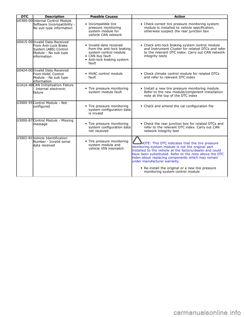
DTC Description Possible Causes Action U0300-00
Internal Control Module
Software Incompatibility -
No sub type information
Incompatible tire
pressure monitoring
system module for
vehicle CAN network
Check correct tire pressure monitoring system
module is installed to vehicle specification,
otherwise suspect the rear junction box U0415-00
Invalid Data Received
From Anti-Lock Brake
System (ABS) Control
Module - No sub type
information
Invalid data received
from the anti-lock braking
system control module
CAN bus fault
Anti-lock braking system
fault
Check anti-lock braking system control module
and Instrument Cluster for related DTCs and refer
to the relevant DTC index. Carry out CAN network
integrity tests U0424-00
Invalid Data Received
From HVAC Control
Module - No sub type
information
HVAC control module
fault
Check climate control module for related DTCs
and refer to relevant DTC index U1A14-49 CAN Initialisation Failure
- Internal electronic
failure
Tire pressure monitoring
system module fault
Install a new tire pressure monitoring module.
Refer to the new module/component installation
note at the top of the DTC index U3000-55
Control Module - Not
configured
Tire pressure monitoring
system configuration data
is invalid
Check and amend the car configuration file U3000-87
Control Module - Missing
message
Tire pressure monitoring
system configuration data
not received
Check the rear junction box for related DTCs and
refer to the relevant DTC index. Carry out CAN
network integrity test U3002-81
Vehicle Identification
Number - Invalid serial
data received
Tire pressure monitoring
system module and
vehicle VIN mismatch
NOTE: This DTC indicates that the tire pressure
monitoring system module is not the original part
installed to the vehicle at the factory/dealer and could
have been substituted. Refer to the note above the DTC
index about replacing components which may remain
under manufacturer warranty.
Re-install the original or a new tire pressure
monitoring system control module