box JAGUAR XFR 2010 1.G Service Manual
[x] Cancel search | Manufacturer: JAGUAR, Model Year: 2010, Model line: XFR, Model: JAGUAR XFR 2010 1.GPages: 3039, PDF Size: 58.49 MB
Page 498 of 3039
Winter Mode
To activate winter mode, press the winter mode button briefly (not less than 300 ms) to activate or de-activate the mode.
NOTE: Winter mode cannot be active at the same time as dynamic mode (Supercharged models only).
When active the winter mode icon and message appear in the instrument cluster message center to confirm the activation.
Dynamic Stability Control (DSC)
Press the DSC mode button briefly (not less than 300 ms) to switch between DSC and TracDSC. The instrument cluster
message center will display either 'DSC ON' or 'TRAC DSC' depending on which selection is made. When TracDSC is selected,
the DSC warning lamp in the instrument cluster is illuminated and the DSC button is illuminated.
DSC can be manually switched off by pressing the DSC mode button for more than 10 seconds. Confirmation is given by a
chime from the instrument cluster, 'DSC OFF' is displayed in the instrument cluster message center and the DSC warning lamp
in the instrument cluster is illuminated.
NOTE: DSC is operational at all times when the engine is running unless manually switched off.
Dynamic Mode (Supercharged models only)
To activate Dynamic mode, press the button briefly. The dynamic mode and DSC buttons are illuminated. 'Dynamic Mode
Confirmed' message is displayed in the instrument cluster message center and the DSC off warning lamp in the instrument
cluster is illuminated (due to automatic selection of TracDSC in Dynamic mode).
NOTE: Dynamic mode cannot be active at the same time as winter mode.
Once activated, TracDSC is automatically selected. In gearbox Sport mode, the driver has full control over the transmission
shift points and the TCM will not intervene to prevent engine overspeed (for example; upshifts are inhibited in gearbox sport mode when Dynamic mode is selected). In this setting, the gear indicator in the instrument cluster will turn amber at high
rev's to indicate an appropriate manual upshift point.
Page 531 of 3039
Published: 11-May-2011
Rear Drive Axle/Differential - Rear Drive Axle and Differential - System
Operation and Component Description
Description and Operation
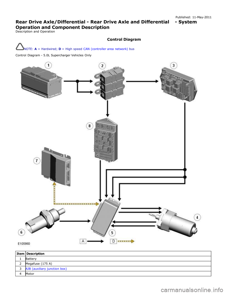
Control Diagram
NOTE: A = Hardwired; D = High speed CAN (controller area network) bus
Control Diagram - 5.0L Supercharger Vehicles Only
Item Description 1 Battery 2 Megafuse (175 A) 3 AJB (auxiliary junction box) 4 Motor
Page 532 of 3039
6 Oil temperature sensor 7 High speed CAN from suspension control module 8 CJB (central junction box)
System Operation
ELECTRONIC
DIFFERENTIAL
-
5.0L
SUPERCHARGER
VEHICLES
FROM
2010MY
The
multi-plate
clutch
prevents
excessive
differential
slip and
therefore
maximizes
the
traction
performance
of
the
vehicle.
This
is
fundamentally
different
from
'braked'
traction
control
systems,
which
can
only
counteract
differential
slip when it
occurs.
A
certain
amount
of
differential
slip is
required
to
allow
the
vehicle
to
turn
corners
and
to
remain
stable
under
control
of
the
ABS
(anti-lock
brake
system).
The
system
is
completely
automatic and
does
not
require
any
special
driver
input.
The
multi-plate
clutch
actively
controls
the
torque
flow
through
the
differential
and
optimizes
the
torque
distribution in
the
driveline.
The
clutch
biases
the
torque
from
the
differential
to
the
wheel
with the
higher
grip
and prevents
the
wheel
with the
lower
grip
from
spinning.
www.JagDocs.com
Page 534 of 3039
A motor and reduction gearbox, attached to the cover.
A temperature sensor installed in the cover.
The DLM (differential locking module) operates the motor of the electronic differential under the control of the ADM (adaptive
damping module).
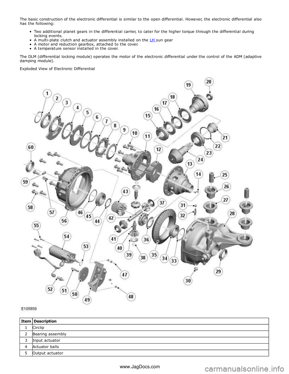
Exploded View of Electronic Differential
Item Description 1 Circlip 2 Bearing assembly 3 Input actuator 4 Actuator balls 5 Output actuator www.JagDocs.com
Page 536 of 3039
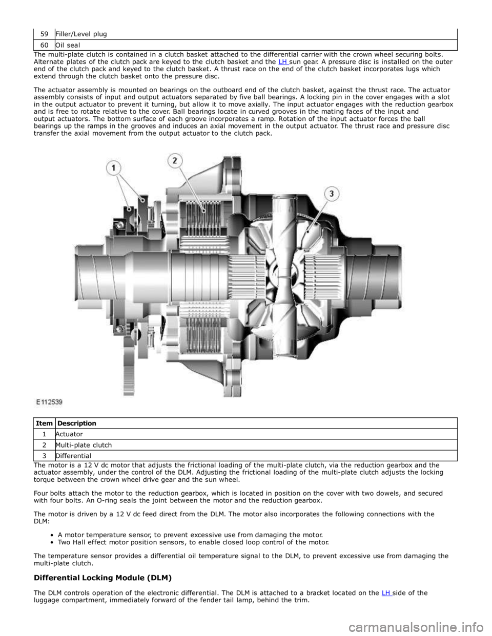
60 Oil seal The multi-plate clutch is contained in a clutch basket attached to the differential carrier with the crown wheel securing bolts.
Alternate plates of the clutch pack are keyed to the clutch basket and the LH sun gear. A pressure disc is installed on the outer end of the clutch pack and keyed to the clutch basket. A thrust race on the end of the clutch basket incorporates lugs which
extend through the clutch basket onto the pressure disc.
The actuator assembly is mounted on bearings on the outboard end of the clutch basket, against the thrust race. The actuator
assembly consists of input and output actuators separated by five ball bearings. A locking pin in the cover engages with a slot
in the output actuator to prevent it turning, but allow it to move axially. The input actuator engages with the reduction gearbox
and is free to rotate relative to the cover. Ball bearings locate in curved grooves in the mating faces of the input and
output actuators. The bottom surface of each groove incorporates a ramp. Rotation of the input actuator forces the ball
bearings up the ramps in the grooves and induces an axial movement in the output actuator. The thrust race and pressure disc
transfer the axial movement from the output actuator to the clutch pack.
Item Description 1 Actuator 2 Multi-plate clutch 3 Differential The motor is a 12 V dc motor that adjusts the frictional loading of the multi-plate clutch, via the reduction gearbox and the
actuator assembly, under the control of the DLM. Adjusting the frictional loading of the multi-plate clutch adjusts the locking
torque between the crown wheel drive gear and the sun wheel.
Four bolts attach the motor to the reduction gearbox, which is located in position on the cover with two dowels, and secured
with four bolts. An O-ring seals the joint between the motor and the reduction gearbox.
The motor is driven by a 12 V dc feed direct from the DLM. The motor also incorporates the following connections with the
DLM:
A motor temperature sensor, to prevent excessive use from damaging the motor.
Two Hall effect motor position sensors, to enable closed loop control of the motor.
The temperature sensor provides a differential oil temperature signal to the DLM, to prevent excessive use from damaging the
multi-plate clutch.
Differential Locking Module (DLM)
The DLM controls operation of the electronic differential. The DLM is attached to a bracket located on the LH side of the luggage compartment, immediately forward of the fender tail lamp, behind the trim.
Page 609 of 3039

Published: 11-May-2011
Front Disc Brake - TDV6 3.0L Diesel /V8 5.0L Petrol/V8 S/C 5.0L Petrol - Front Disc Brake - System Operation and Component Description
Description and Operation
Control Diagram
NOTE: A = Hardwired
Item Description 1 Battery 2 Megafuse (250 A) 3 Front brake pad wear sensor 4 Rear brake pad wear sensor 5 Instrument cluster 6 CJB (central junction box) 7 Power distribution box
Page 631 of 3039

Published: 11-May-2011
Rear Disc Brake - TDV6 3.0L Diesel /V8 5.0L Petrol/V8 S/C 5.0L Petrol - Rear
Disc Brake - System Operation and Component Description
Description and Operation
Control Diagram
NOTE: A = Hardwired
Item Description 1 Battery 2 Megafuse (250 A) 3 Front brake pad wear sensor 4 Rear brake pad wear sensor 5 Instrument cluster 6 CJB (central junction box) 7Powerdistributionbox
Page 647 of 3039
Published: 11-May-2011
Parking Brake and Actuation - Parking Brake - System Operation and
Component Description
Description and Operation
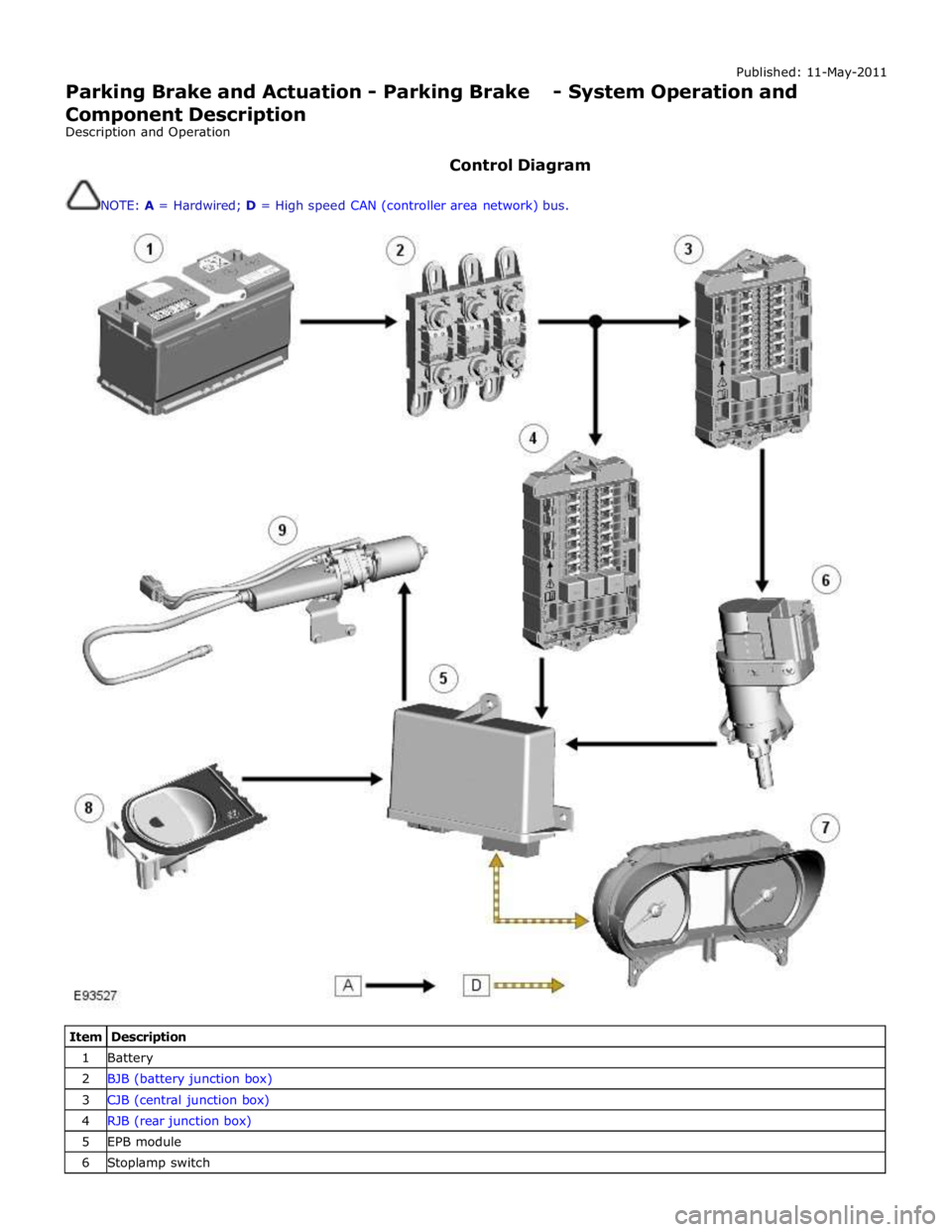
Control Diagram
NOTE: A = Hardwired; D = High speed CAN (controller area network) bus.
Item Description 1 Battery 2 BJB (battery junction box) 3 CJB (central junction box) 4 RJB (rear junction box) 5 EPB module 6 Stoplamp switch
Page 651 of 3039

Stoplamp Switch
The stoplamp switch is mounted on the brake pedal box. One of the prerequisites for releasing the parking brake is that the
foot brake is applied. The EPB module is able to determine the position of the footbrake by monitoring the status of the
stoplamp switch via a hardwired electrical connection.
The stoplamp switch also forms part of:
The ABS. Refer to: Anti-Lock Control - Stability Assist (206-09 Anti-Lock Control - Stability Assist, Description and Operation). The speed control system. For additional information, refer to:
Speed Control (310-03A, Description and Operation),
Speed Control (310-03B, Description and Operation),
Speed Control (310-03C, Description and Operation).
Page 680 of 3039

6. Release the fuse box.
7. Remove the brake master cylinder.
Installation
1. To install, reverse the removal procedure.
Install new O-ring seals. www.JagDocs.com