box JAGUAR XFR 2010 1.G Repair Manual
[x] Cancel search | Manufacturer: JAGUAR, Model Year: 2010, Model line: XFR, Model: JAGUAR XFR 2010 1.GPages: 3039, PDF Size: 58.49 MB
Page 687 of 3039
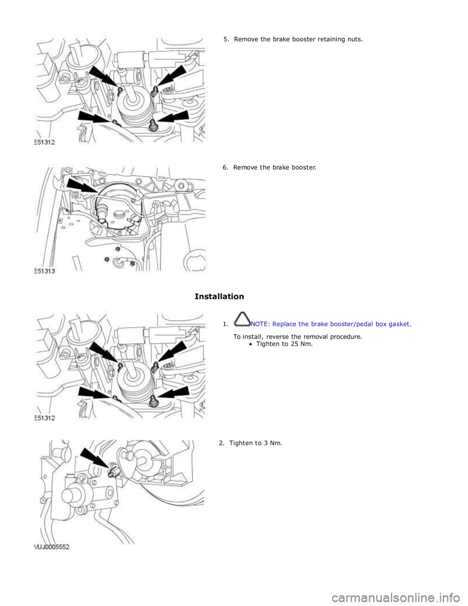
5. Remove the brake booster retaining nuts.
6. Remove the brake booster.
Installation
1. NOTE: Replace the brake booster/pedal box gasket.
To install, reverse the removal procedure.
Tighten to 25 Nm.
2. Tighten to 3 Nm.
Page 693 of 3039
Published: 11-May-2011
Anti-Lock Control - Stability Assist - Anti-Lock Control - Stability Assist - System Operation and Component Description
Description and Operation
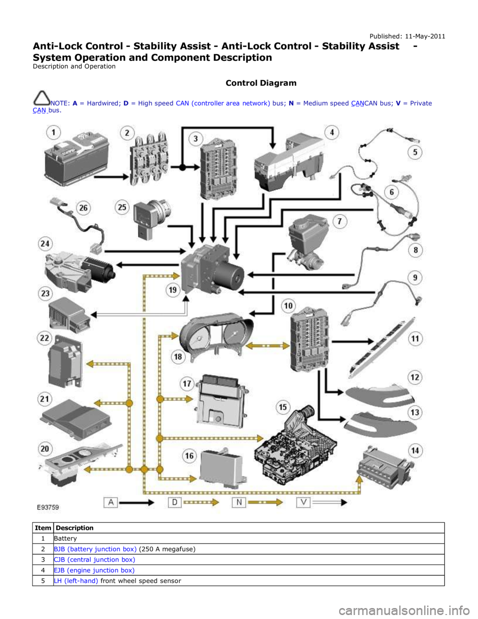
Control Diagram
NOTE: A = Hardwired; D = High speed CAN (controller area network) bus; N = Medium speed CANCAN bus; V = Private CAN bus.
Item Description 1 Battery 2 BJB (battery junction box) (250 A megafuse) 3 CJB (central junction box) 4 EJB (engine junction box) 5 LH (left-hand) front wheel speed sensor
Page 694 of 3039
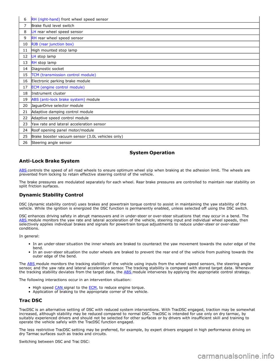
7 Brake fluid level switch 8 LH rear wheel speed sensor 9 RH rear wheel speed sensor 10 RJB (rear junction box) 11 High mounted stop lamp 12 LH stop lamp 13 RH stop lamp 14 Diagnostic socket 15 TCM (transmission control module) 16 Electronic parking brake module 17 ECM (engine control module) 18 Instrument cluster 19 ABS (anti-lock brake system) module 20 JaguarDrive selector module 21 Adaptive damping control module 22 Adaptive speed control module 23 Yaw rate and lateral acceleration sensor 24 Roof opening panel motor/module 25 Brake booster vacuum sensor (3.0L vehicles only) 26 Steering angle sensor
Anti-Lock Brake System System Operation
ABS controls the speed of all road wheels to ensure optimum wheel slip when braking at the adhesion limit. The wheels are prevented from locking to retain effective steering control of the vehicle.
The brake pressures are modulated separately for each wheel. Rear brake pressures are controlled to maintain rear stability on
split friction surfaces.
Dynamic Stability Control
DSC (dynamic stability control) uses brakes and powertrain torque control to assist in maintaining the yaw stability of the
vehicle. While the ignition is energized the DSC function is permanently enabled, unless selected off using the DSC switch.
DSC enhances driving safety in abrupt maneuvers and in under-steer or over-steer situations that may occur in a bend. The
ABS module monitors the yaw rate and lateral acceleration of the vehicle, steering input and individual wheel speeds, then selectively applies individual brakes and signals for powertrain torque adjustments to reduce under-steer or over-steer
conditions.
In general:
In an under-steer situation the inner wheels are braked to counteract the yaw movement towards the outer edge of the
bend.
In an over-steer situation the outer wheels are braked to prevent the rear end of the vehicle from pushing towards the
outer edge of the bend.
The ABS module monitors the tracking stability of the vehicle using inputs from the wheel speed sensors, the steering angle sensor, and the yaw rate and lateral acceleration sensor. The tracking stability is compared with stored target data. Whenever
the tracking stability deviates from the target data, the ABS module intervenes by applying the appropriate control strategy. The following interactions occur in an intervention situation:
High speed CAN signal to the ECM, to reduce engine torque. Application of braking to the appropriate corner of the vehicle.
Trac DSC
TracDSC is an alternative setting of DSC with reduced system interventions. With TracDSC engaged, traction may be somewhat
increased, although stability may be reduced compared to normal DSC. TracDSC is intended for use only on dry tarmac, by
suitably experienced drivers and should not be selected for other surfaces or by drivers with insufficient skill and training to
operate the vehicle safely with the TracDSC function engaged.
The less restrictive TracDSC setting may be preferred, for example, by expert drivers engaged in high performance driving on
dry Tarmac surfaces such as tracks and circuits.
Switching between DSC and Trac DSC:
Page 700 of 3039

Stoplamp Switch
The stoplamp switch is mounted on the brake pedal box and is connected to the vehicle harness via a four pin multiplug.
When the brake pedal is pressed, the switch contacts close. This allows a hard wired signal feed to be sent to the ECM. A stoplamp switch status message is then sent from the ECM to the ABS module on the high speed CAN bus. The ABS module is then able to control braking force accordingly in conjunction with the HCU.
NOTE: The stoplamp switch also forms part of the speed control system.
For additional information, refer to:
Speed Control (310-03 Speed Control - 2.7L V6 - TdV6, Description and Operation),
Speed Control (310-03 Speed Control - 3.0L NA V6 - AJ27, Description and Operation),
Speed Control (310-03 Speed Control - 4.2L NA V8 - AJV8/4.2L SC V8 - AJV8, Description and Operation). www.JagDocs.com
Page 778 of 3039

Published: 20-May-2014
Steering Column - Steering Column - System Operation and Component Description
Description and Operation
Control Diagram
NOTE: A = Hardwired; D = High speed CAN bus; N = Medium speed CAN bus
Item Description 1 Battery 2 BJB (battery junction box) - Megafuse (175A) 3 RJB (rear junction box) 4 Electric steering column lock 5 High Speed CAN (controller area network) bus to other vehicle systems 6 CJB (central junction box)
Page 798 of 3039
Published: 11-May-2011
Steering Column Switches - Steering Column Switches - System Operation
and Component Description
Description and Operation
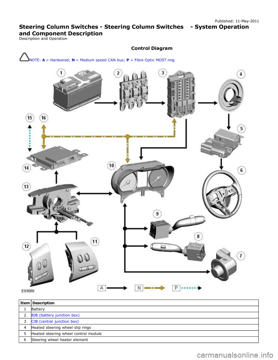
Control Diagram
NOTE: A = Hardwired; N = Medium speed CAN bus; P = Fibre Optic MOST ring
Item Description 1 Battery 2 BJB (battery junction box) 3 CJB (central junction box) 4 Heated steering wheel slip rings 5 Heated steering wheel control module 6 Steering wheel heater element
Page 804 of 3039
Steering Column Switches - Steering Column Switches
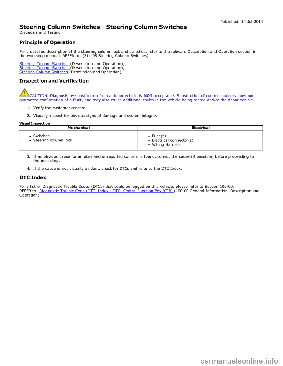
Diagnosis and Testing
Principle of Operation Published: 14-Jul-2014
For a detailed description of the steering column lock and switches, refer to the relevant Description and Operation section in
the workshop manual. REFER to: (211-05 Steering Column Switches)
Steering Column Switches (Description and Operation), Steering Column Switches (Description and Operation), Steering Column Switches (Description and Operation).
Inspection and Verification
CAUTION: Diagnosis by substitution from a donor vehicle is NOT acceptable. Substitution of control modules does not
guarantee confirmation of a fault, and may also cause additional faults in the vehicle being tested and/or the donor vehicle.
1. Verify the customer concern.
2. Visually inspect for obvious signs of damage and system integrity.
Visual Inspection
Mechanical Electrical
Switches
Steering column lock
Fuse(s)
Electrical connector(s)
Wiring Harness
3. If an obvious cause for an observed or reported concern is found, correct the cause (if possible) before proceeding to
the next step.
4. If the cause is not visually evident, check for DTCs and refer to the DTC Index.
DTC Index
For a list of Diagnostic Trouble Codes (DTCs) that could be logged on this vehicle, please refer to Section 100-00.
REFER to: Diagnostic Trouble Code (DTC) Index - DTC: Central Junction Box (CJB) (100-00 General Information, Description and Operation).
Page 1112 of 3039
Published: 11-May-2011
Engine Cooling - V8 5.0L Petrol/V8 S/C 5.0L Petrol - Engine Cooling - System
Operation and Component Description
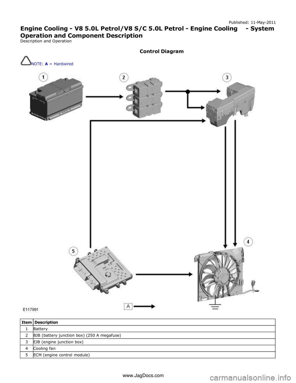
Description and Operation
Control Diagram
NOTE: A = Hardwired
Item Description 1 Battery 2 BJB (battery junction box) (250 A megafuse) 3 EJB (engine junction box) 4 Cooling fan 5 ECM (engine control module) www.JagDocs.com
Page 1114 of 3039
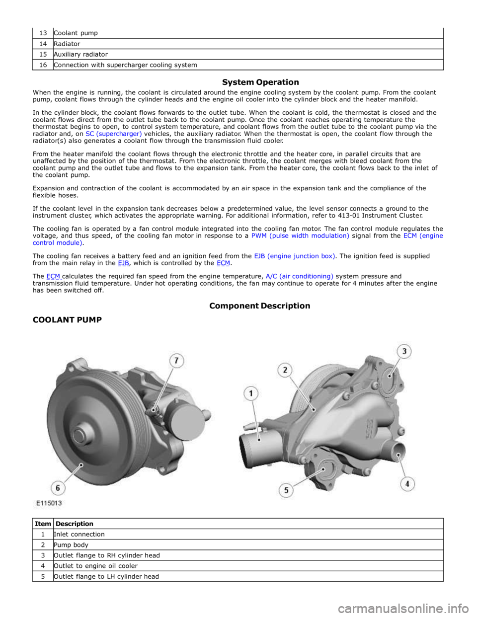
14 Radiator 15 Auxiliary radiator 16 Connection with supercharger cooling system
System Operation
When the engine is running, the coolant is circulated around the engine cooling system by the coolant pump. From the coolant
pump, coolant flows through the cylinder heads and the engine oil cooler into the cylinder block and the heater manifold.
In the cylinder block, the coolant flows forwards to the outlet tube. When the coolant is cold, the thermostat is closed and the
coolant flows direct from the outlet tube back to the coolant pump. Once the coolant reaches operating temperature the
thermostat begins to open, to control system temperature, and coolant flows from the outlet tube to the coolant pump via the
radiator and, on SC (supercharger) vehicles, the auxiliary radiator. When the thermostat is open, the coolant flow through the
radiator(s) also generates a coolant flow through the transmission fluid cooler.
From the heater manifold the coolant flows through the electronic throttle and the heater core, in parallel circuits that are
unaffected by the position of the thermostat. From the electronic throttle, the coolant merges with bleed coolant from the
coolant pump and the outlet tube and flows to the expansion tank. From the heater core, the coolant flows back to the inlet of
the coolant pump.
Expansion and contraction of the coolant is accommodated by an air space in the expansion tank and the compliance of the
flexible hoses.
If the coolant level in the expansion tank decreases below a predetermined value, the level sensor connects a ground to the
instrument cluster, which activates the appropriate warning. For additional information, refer to 413-01 Instrument Cluster.
The cooling fan is operated by a fan control module integrated into the cooling fan motor. The fan control module regulates the
voltage, and thus speed, of the cooling fan motor in response to a PWM (pulse width modulation) signal from the ECM (engine
control module).
The cooling fan receives a battery feed and an ignition feed from the EJB (engine junction box). The ignition feed is supplied
from the main relay in the EJB, which is controlled by the ECM.
The ECM calculates the required fan speed from the engine temperature, A/C (air conditioning) system pressure and transmission fluid temperature. Under hot operating conditions, the fan may continue to operate for 4 minutes after the engine
has been switched off.
COOLANT PUMP Component Description
Item Description 1 Inlet connection 2 Pump body 3 Outlet flange to RH cylinder head 4 Outlet to engine oil cooler 5 Outlet flange to LH cylinder head
Page 1124 of 3039
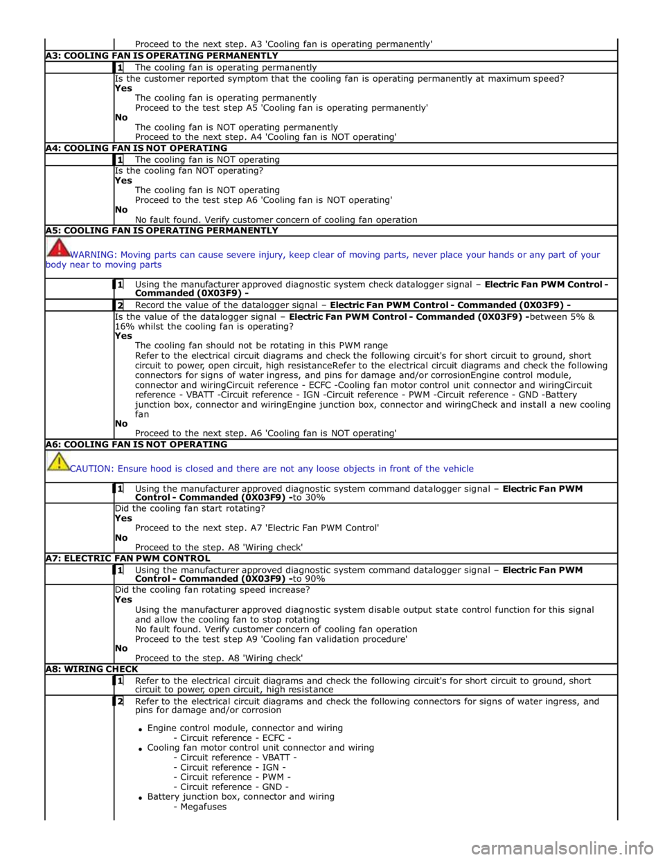
Proceed to the next step. A3 'Cooling fan is operating permanently' A3: COOLING FAN IS OPERATING PERMANENTLY 1 The cooling fan is operating permanently Is the customer reported symptom that the cooling fan is operating permanently at maximum speed?
Yes
The cooling fan is operating permanently
Proceed to the test step A5 'Cooling fan is operating permanently'
No
The cooling fan is NOT operating permanently
Proceed to the next step. A4 'Cooling fan is NOT operating' A4: COOLING FAN IS NOT OPERATING 1 The cooling fan is NOT operating Is the cooling fan NOT operating?
Yes
The cooling fan is NOT operating
Proceed to the test step A6 'Cooling fan is NOT operating'
No
No fault found. Verify customer concern of cooling fan operation A5: COOLING FAN IS OPERATING PERMANENTLY
WARNING: Moving parts can cause severe injury, keep clear of moving parts, never place your hands or any part of your
body near to moving parts 1 Using the manufacturer approved diagnostic system check datalogger signal – Electric Fan PWM Control - Commanded (0X03F9) - 2 Record the value of the datalogger signal – Electric Fan PWM Control - Commanded (0X03F9) - Is the value of the datalogger signal – Electric Fan PWM Control - Commanded (0X03F9) -between 5% &
16% whilst the cooling fan is operating?
Yes
The cooling fan should not be rotating in this PWM range
Refer to the electrical circuit diagrams and check the following circuit's for short circuit to ground, short
circuit to power, open circuit, high resistanceRefer to the electrical circuit diagrams and check the following
connectors for signs of water ingress, and pins for damage and/or corrosionEngine control module,
connector and wiringCircuit reference - ECFC -Cooling fan motor control unit connector and wiringCircuit
reference - VBATT -Circuit reference - IGN -Circuit reference - PWM -Circuit reference - GND -Battery
junction box, connector and wiringEngine junction box, connector and wiringCheck and install a new cooling
fan
No
Proceed to the next step. A6 'Cooling fan is NOT operating' A6: COOLING FAN IS NOT OPERATING
CAUTION: Ensure hood is closed and there are not any loose objects in front of the vehicle 1 Using the manufacturer approved diagnostic system command datalogger signal – Electric Fan PWM Control - Commanded (0X03F9) -to 30% Did the cooling fan start rotating?
Yes
Proceed to the next step. A7 'Electric Fan PWM Control'
No
Proceed to the step. A8 'Wiring check' A7: ELECTRIC FAN PWM CONTROL 1 Using the manufacturer approved diagnostic system command datalogger signal – Electric Fan PWM Control - Commanded (0X03F9) -to 90% Did the cooling fan rotating speed increase?
Yes
Using the manufacturer approved diagnostic system disable output state control function for this signal
and allow the cooling fan to stop rotating
No fault found. Verify customer concern of cooling fan operation
Proceed to the test step A9 'Cooling fan validation procedure'
No
Proceed to the step. A8 'Wiring check' A8: WIRING CHECK 1 Refer to the electrical circuit diagrams and check the following circuit's for short circuit to ground, short circuit to power, open circuit, high resistance 2 Refer to the electrical circuit diagrams and check the following connectors for signs of water ingress, and pins for damage and/or corrosion
Engine control module, connector and wiring
- Circuit reference - ECFC -
Cooling fan motor control unit connector and wiring
- Circuit reference - VBATT -
- Circuit reference - IGN -
- Circuit reference - PWM -
- Circuit reference - GND -
Battery junction box, connector and wiring
- Megafuses