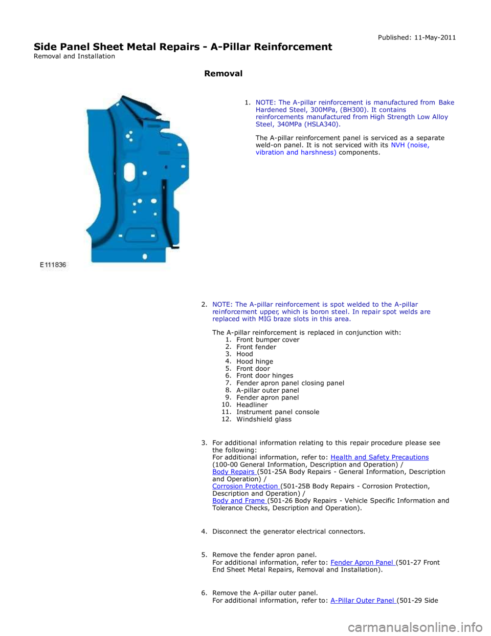
JAGUAR XFR 2010 1.G Workshop Manual
XFR 2010 1.G
JAGUAR
JAGUAR
https://www.carmanualsonline.info/img/21/7642/w960_7642-0.png
JAGUAR XFR 2010 1.G Workshop Manual
Trending: Rear Drive, wheel alignment, ESP, tilt, fog light bulb, transmission oil, ABS
Page 2851 of 3039
9. Offer up the new panel and clamp into position. Check alignment, if
correct, proceed to next step, if not rectify and recheck before
proceeding.
10. Remove the new A-pillar outer panel.
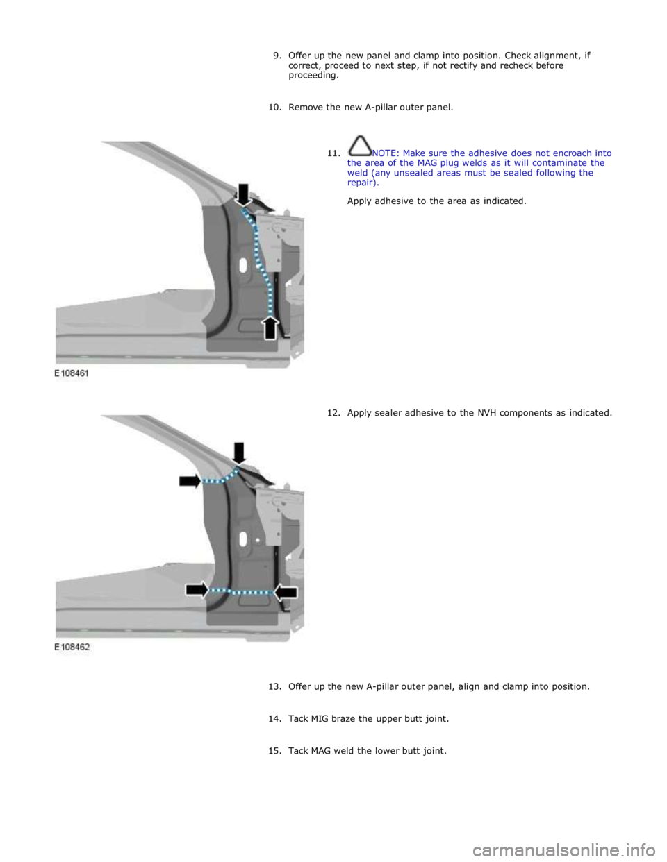
11.
12. NOTE: Make sure the adhesive does not encroach into
the area of the MAG plug welds as it will contaminate the
weld (any unsealed areas must be sealed following the
repair).
Apply adhesive to the area as indicated.
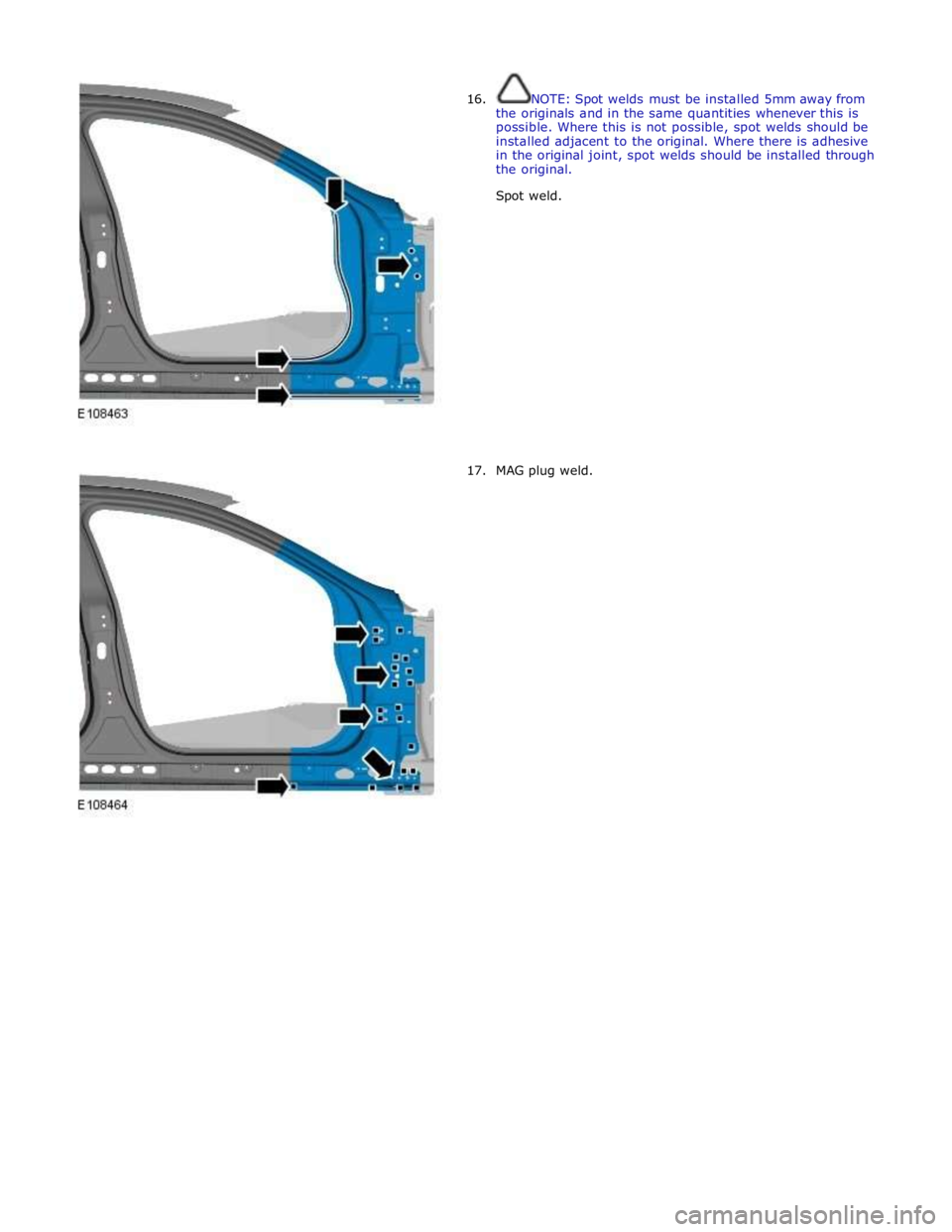
Apply sealer adhesive to the NVH components as indicated.
13.
Offer up the new A-pillar outer panel, align and clamp into position.
14. Tack MIG braze the upper butt joint.
15. Tack MAG weld the lower butt joint.
Page 2852 of 3039
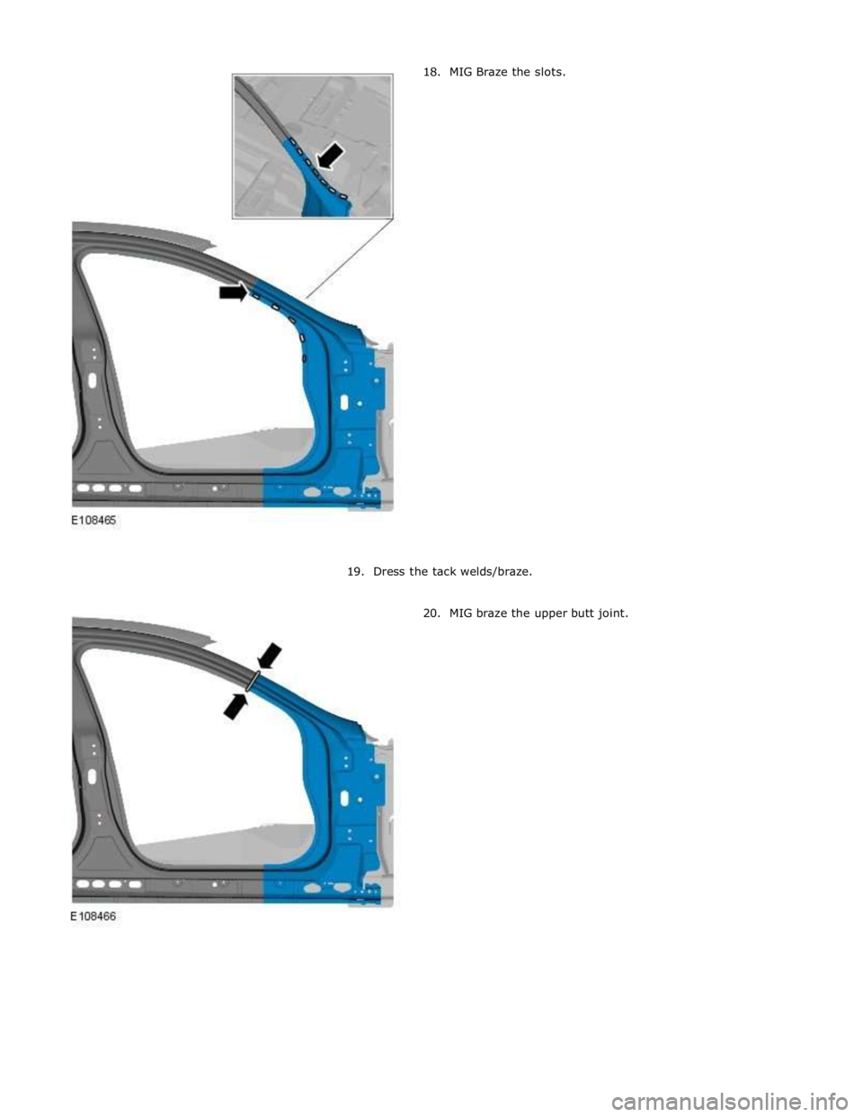
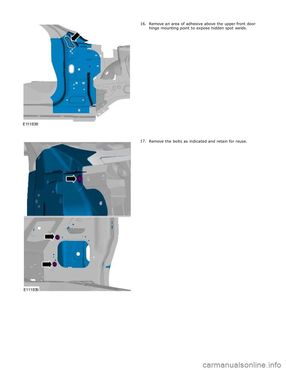
16.
17. NOTE: Spot welds must be installed 5mm away from
the originals and in the same quantities whenever this is
possible. Where this is not possible, spot welds should be
installed adjacent to the original. Where there is adhesive
in the original joint, spot welds should be installed through
the original.
Spot weld.
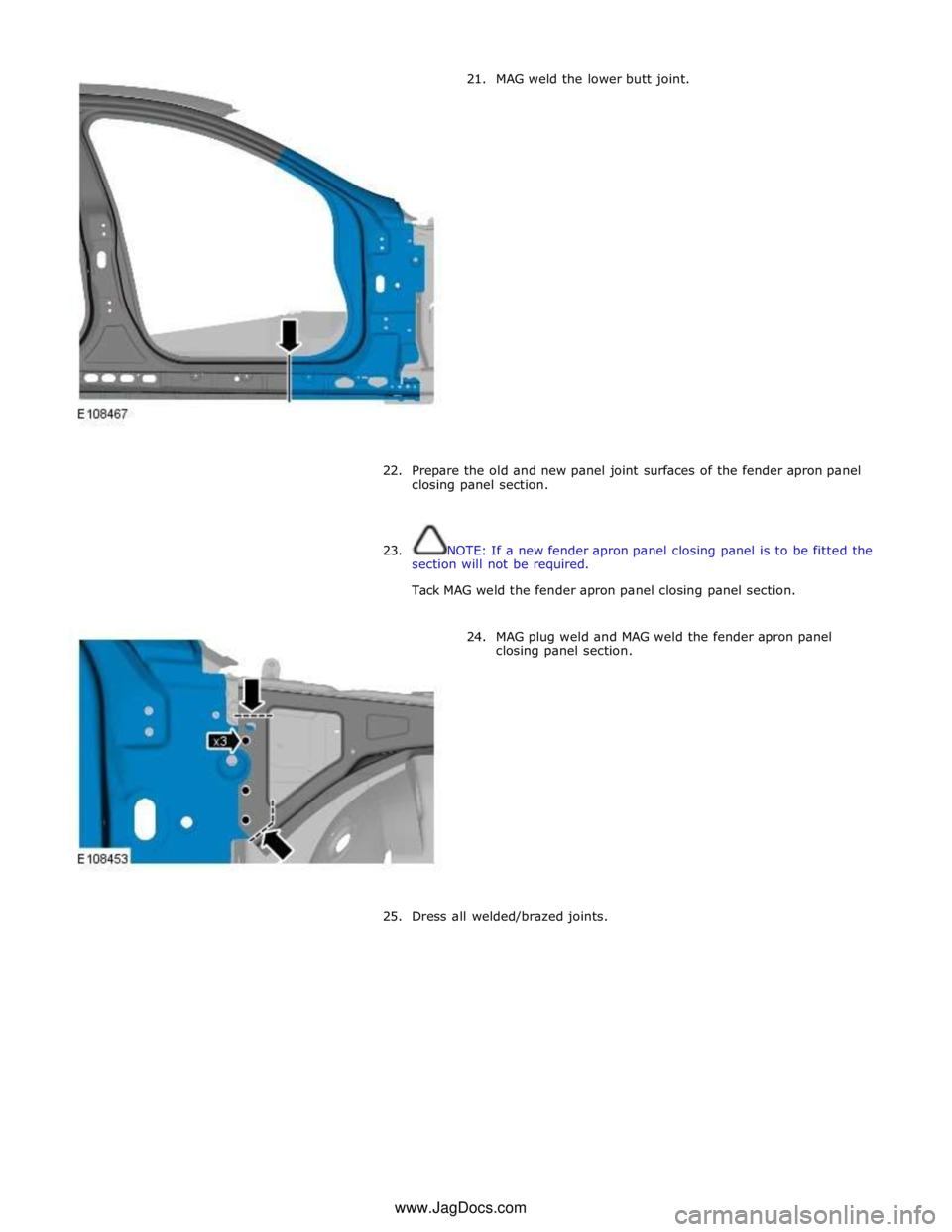
MAG plug weld.
Page 2853 of 3039
Page 2854 of 3039
21. MAG weld the lower butt joint.
22.
Prepare the old and new panel joint surfaces of the fender apron panel
closing panel section.
23. NOTE: If a new fender apron panel closing panel is to be fitted the
section will not be required.
Tack MAG weld the fender apron panel closing panel section.
24. MAG plug weld and MAG weld the fender apron panel
closing panel section.
25. Dress all welded/brazed joints. www.JagDocs.com
Page 2855 of 3039
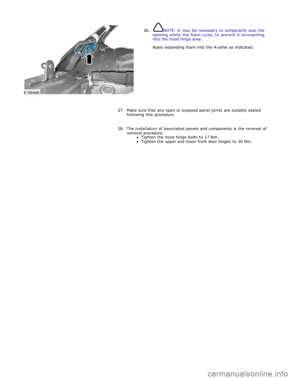
26. NOTE: It may be necessary to temporarily seal the
opening whilst the foam cures, to prevent it encroaching
into the hood hinge area.
Apply expanding foam into the A-pillar as indicated.
27. Make sure that any open or exposed panel joints are suitably sealed
following this procedure.
28. The installation of associated panels and components is the reversal of
removal procedure.
Tighten the hood hinge bolts to 17 Nm.
Tighten the upper and lower front door hinges to 30 Nm.
Page 2856 of 3039
(100-00 General Information, Description and Operation) /
Body Repairs (501-25A Body Repairs - General Information, Description and Operation) /
Corrosion Protection (501-25B Body Repairs - Corrosion Protection, Description and Operation) /
Body and Frame (501-26 Body Repairs - Vehicle Specific Information and Tolerance Checks, Description and Operation).
4. Disconnect the generator electrical connectors.
5. Remove the fender apron panel.
For additional information, refer to: Fender Apron Panel (501-27 Front End Sheet Metal Repairs, Removal and Installation).
6. Remove the A-pillar outer panel.
For additional information, refer to: A-Pillar Outer Panel (501-29 Side
Page 2857 of 3039

Panel Sheet Metal Repairs, Removal and Installation).
7. Remove the side air curtain module.
For additional information, refer to: Side Air Curtain Module (501-20B Supplemental Restraint System, Removal and Installation).
8. Remove the front seat.
For additional information, refer to: Front Seat (501-10 Seating, Removal and Installation).
9. Remove the floor covering.
10. If the passenger side A-pillar reinforcement is to be repaired, remove
the heater core and evaporator core housing.
For additional information, refer to: Heater Core and Evaporator Core Housing (412-01 Climate Control, Removal and Installation).
11. If the right-hand A-pillar reinforcement is to be repaired, remove the
central junction box.
For additional information, refer to: Central Junction Box (CJB) (418-00 Module Communications Network, Removal and Installation).
12. If the drivers side A-pillar reinforcement is to be repaired, remove the
pedal box.
13. Release and lay aside the insulating material at the inner bulkhead.
14. Release and position aside the inner bulkhead and floor panel wiring
harness.
15. NOTE: The NVH components may have already been
removed on the outer panel.
Remove the upper and lower NVH components and if
undamaged retain for reuse.
Page 2858 of 3039
Page 2859 of 3039
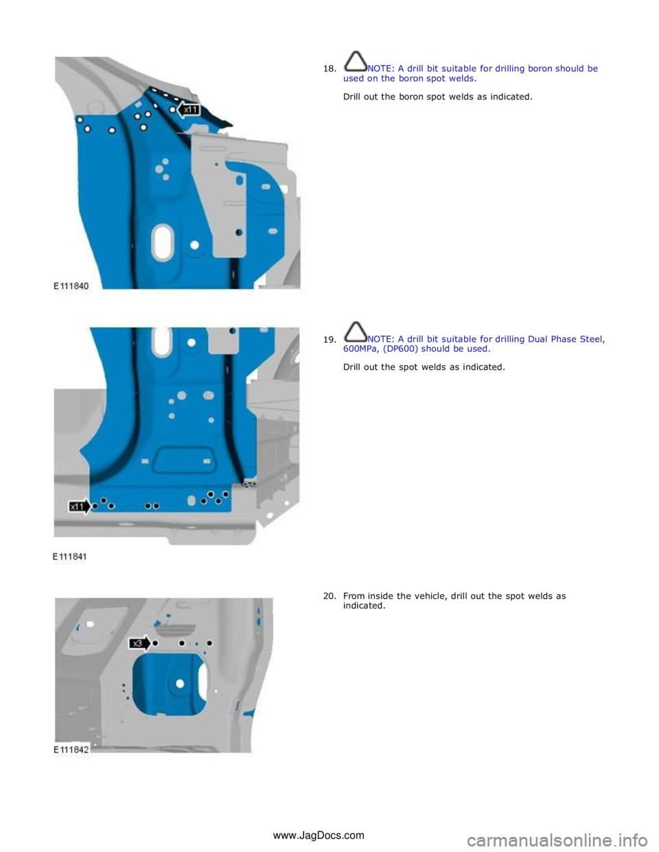
18.
19.
20. NOTE: A drill bit suitable for drilling boron should be
used on the boron spot welds.
Drill out the boron spot welds as indicated.
NOTE: A drill bit suitable for drilling Dual Phase Steel,
600MPa, (DP600) should be used.
Drill out the spot welds as indicated.
From inside the vehicle, drill out the spot welds as
indicated. www.JagDocs.com
Page 2860 of 3039
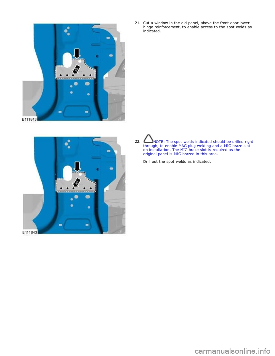
21.
22. Cut a window in the old panel, above the front door lower
hinge reinforcement, to enable access to the spot welds as
indicated.
NOTE: The spot welds indicated should be drilled right
through, to enable MAG plug welding and a MIG braze slot
on installation. The MIG braze slot is required as the
original panel is MIG brazed in this area.
Drill out the spot welds as indicated.
Trending: open gas tank, u0142, isofix, change wheel, service indicator, Key, sat nav
