JAGUAR XFR 2010 1.G Workshop Manual
XFR 2010 1.G
JAGUAR
JAGUAR
https://www.carmanualsonline.info/img/21/7642/w960_7642-0.png
JAGUAR XFR 2010 1.G Workshop Manual
Trending: transmission fluid, B1B86-15, P0700, b100d-87, U2101, drain bolt, u0256
Page 2841 of 3039
Page 2842 of 3039
Page 2843 of 3039
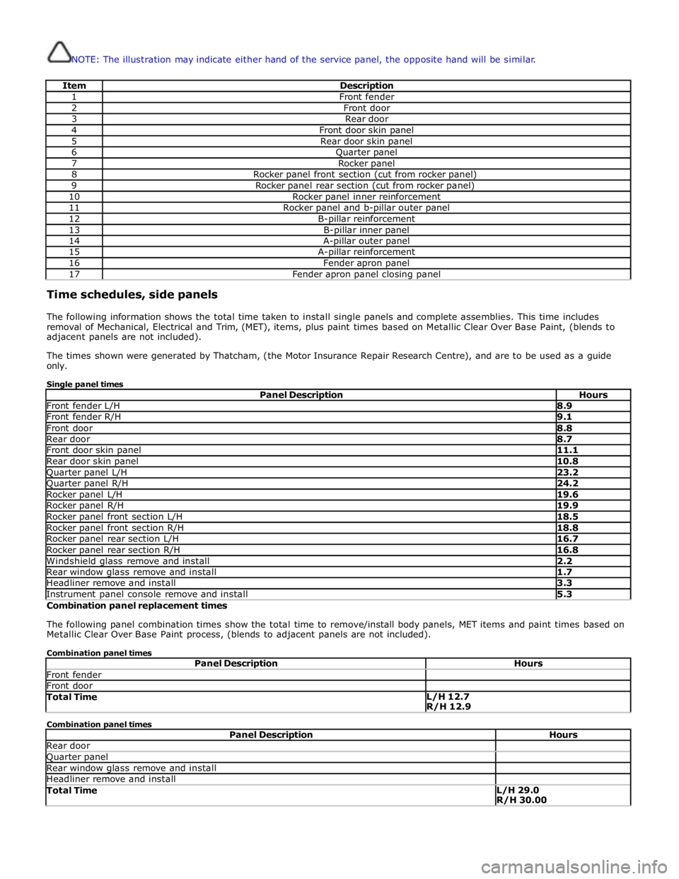
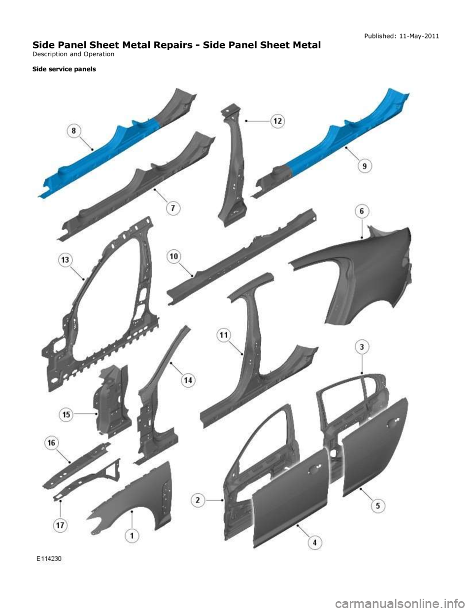
NOTE: The illustration may indicate either hand of the service panel, the opposite hand will be similar.
Item Description 1 Front fender 2 Front door 3 Rear door 4 Front door skin panel 5 Rear door skin panel 6 Quarter panel 7 Rocker panel 8 Rocker panel front section (cut from rocker panel) 9 Rocker panel rear section (cut from rocker panel) 10 Rocker panel inner reinforcement 11 Rocker panel and b-pillar outer panel 12 B-pillar reinforcement 13 B-pillar inner panel 14 A-pillar outer panel 15 A-pillar reinforcement 16 Fender apron panel 17 Fender apron panel closing panel Time schedules, side panels
The following information shows the total time taken to install single panels and complete assemblies. This time includes
removal of Mechanical, Electrical and Trim, (MET), items, plus paint times based on Metallic Clear Over Base Paint, (blends to
adjacent panels are not included).
The times shown were generated by Thatcham, (the Motor Insurance Repair Research Centre), and are to be used as a guide
only.
Single panel times
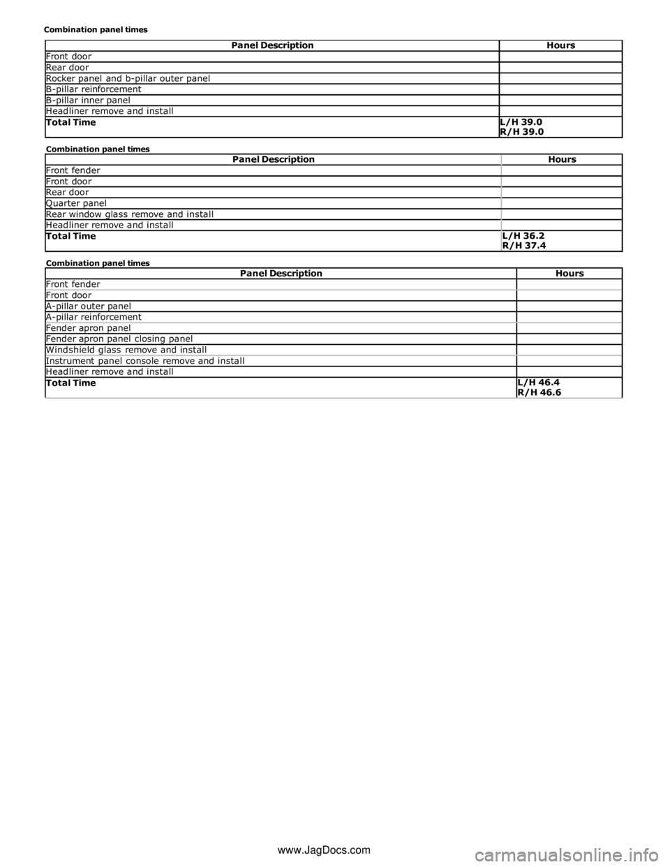
Panel Description Hours Front fender L/H 8.9 Front fender R/H 9.1 Front door 8.8 Rear door 8.7 Front door skin panel 11.1 Rear door skin panel 10.8 Quarter panel L/H 23.2 Quarter panel R/H 24.2 Rocker panel L/H 19.6 Rocker panel R/H 19.9 Rocker panel front section L/H 18.5 Rocker panel front section R/H 18.8 Rocker panel rear section L/H 16.7 Rocker panel rear section R/H 16.8 Windshield glass remove and install 2.2 Rear window glass remove and install 1.7 Headliner remove and install 3.3 Instrument panel console remove and install 5.3 Combination panel replacement times
The following panel combination times show the total time to remove/install body panels, MET items and paint times based on
Metallic Clear Over Base Paint process, (blends to adjacent panels are not included).
Combination panel times
Panel Description Hours Front fender Front door Total Time L/H 12.7
R/H 12.9 Combination panel times
Panel Description Hours Rear door Quarter panel Rear window glass remove and install Headliner remove and install Total Time L/H 29.0
R/H 30.00
Page 2844 of 3039
Front door Rear door Rocker panel and b-pillar outer panel B-pillar reinforcement B-pillar inner panel Headliner remove and install Total Time L/H 39.0
R/H 39.0 Combination panel times
Panel Description Hours Front fender Front door Rear door Quarter panel Rear window glass remove and install Headliner remove and install Total Time L/H 36.2
R/H 37.4 Combination panel times
Panel Description Hours Front fender Front door A-pillar outer panel A-pillar reinforcement Fender apron panel Fender apron panel closing panel Windshield glass remove and install Instrument panel console remove and install Headliner remove and install Total Time L/H 46.4
R/H 46.6 www.JagDocs.com
Page 2845 of 3039
(100-00 General Information, Description and Operation) /
Body Repairs (501-25A Body Repairs - General Information, Description and Operation) /
Corrosion Protection (501-25B Body Repairs - Corrosion Protection, Description and Operation) /
Body and Frame (501-26 Body Repairs - Vehicle Specific Information and Tolerance Checks, Description and Operation).
5. Disconnect the generator electrical connectors.
6. Remove the instrument panel console.
For additional information, refer to: Instrument Panel Console (501-12 Instrument Panel and Console, Removal and Installation).
Page 2846 of 3039
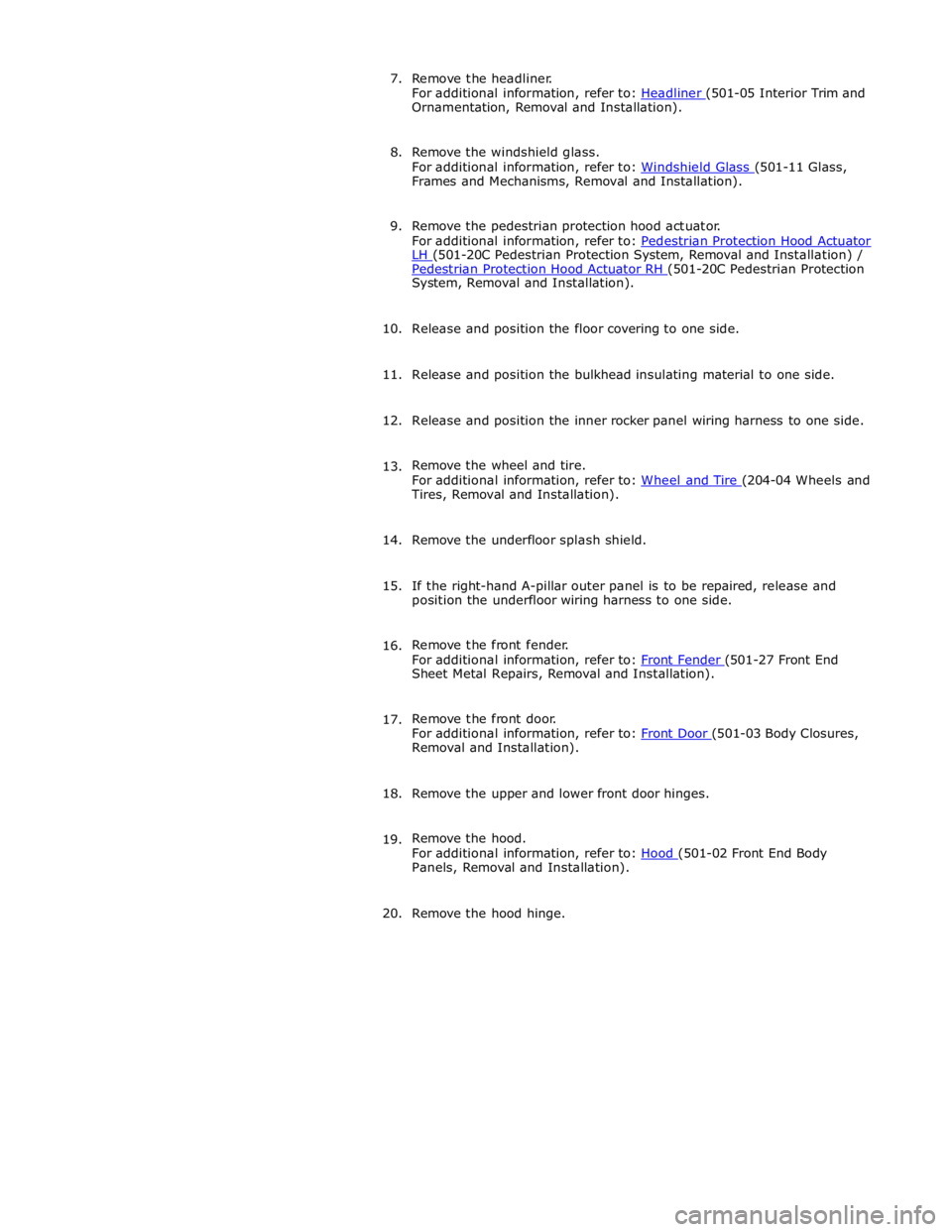
Ornamentation, Removal and Installation).
8. Remove the windshield glass.
For additional information, refer to: Windshield Glass (501-11 Glass, Frames and Mechanisms, Removal and Installation).
9. Remove the pedestrian protection hood actuator.
For additional information, refer to: Pedestrian Protection Hood Actuator LH (501-20C Pedestrian Protection System, Removal and Installation) / Pedestrian Protection Hood Actuator RH (501-20C Pedestrian Protection System, Removal and Installation).
10. Release and position the floor covering to one side.
11. Release and position the bulkhead insulating material to one side.
12. Release and position the inner rocker panel wiring harness to one side.
13. Remove the wheel and tire.
For additional information, refer to: Wheel and Tire (204-04 Wheels and Tires, Removal and Installation).
14. Remove the underfloor splash shield.
15. If the right-hand A-pillar outer panel is to be repaired, release and
position the underfloor wiring harness to one side.
16. Remove the front fender.
For additional information, refer to: Front Fender (501-27 Front End Sheet Metal Repairs, Removal and Installation).
17. Remove the front door.
For additional information, refer to: Front Door (501-03 Body Closures, Removal and Installation).
18. Remove the upper and lower front door hinges.
19. Remove the hood.
For additional information, refer to: Hood (501-02 Front End Body Panels, Removal and Installation).
20. Remove the hood hinge.
Page 2847 of 3039
21.
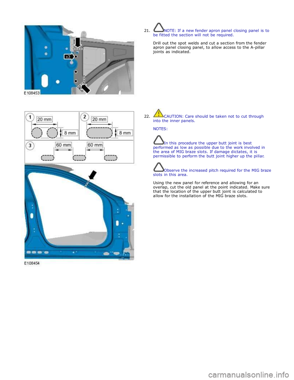
22. NOTE: If a new fender apron panel closing panel is to
be fitted the section will not be required.
Drill out the spot welds and cut a section from the fender
apron panel closing panel, to allow access to the A-pillar
joints as indicated.
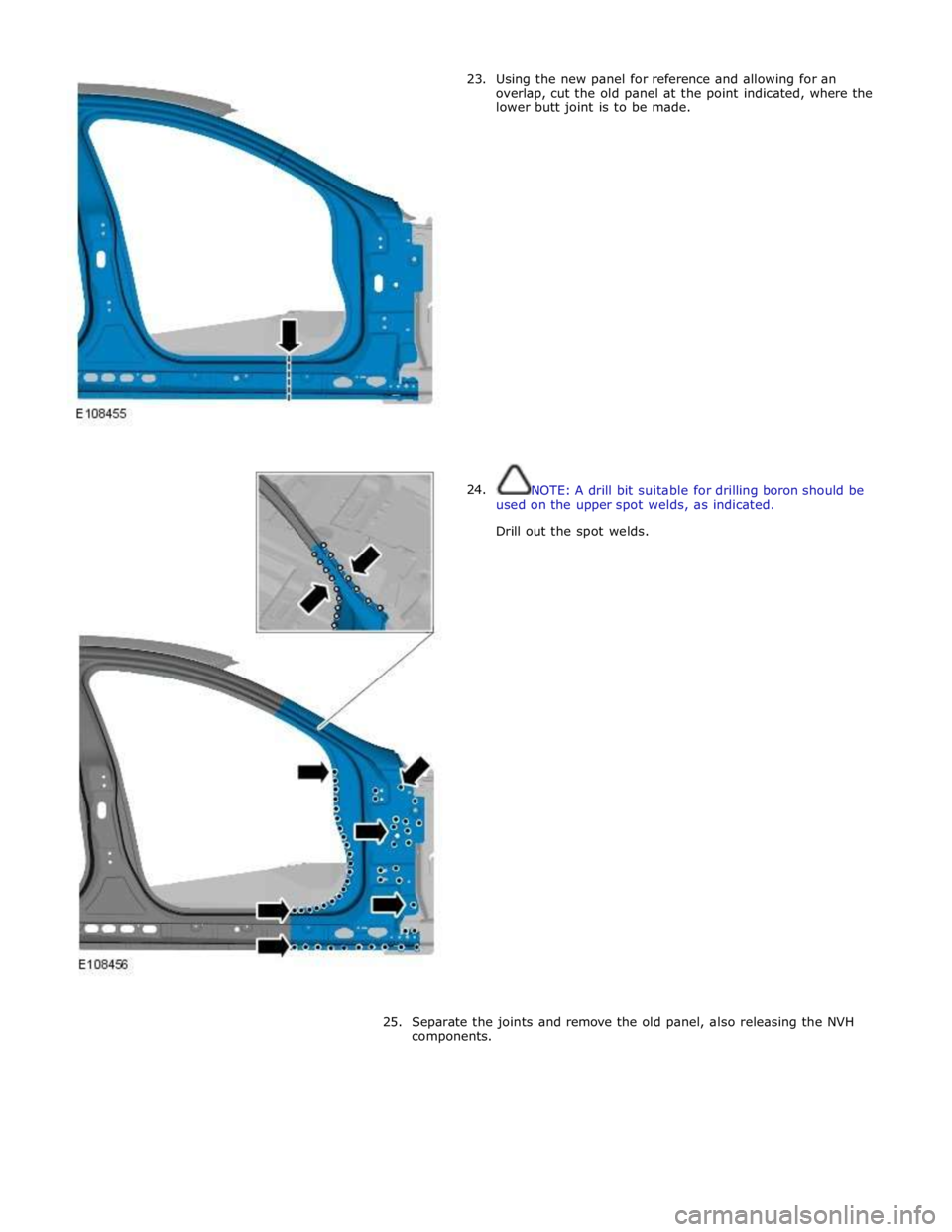
CAUTION: Care should be taken not to cut through
into the inner panels.
NOTES:
In this procedure the upper butt joint is best
performed as low as possible due to the work involved in
the area of MIG braze slots. If damage dictates, it is
permissible to perform the butt joint higher up the pillar.
Observe the increased pitch required for the MIG braze
slots in this area.
Using the new panel for reference and allowing for an
overlap, cut the old panel at the point indicated. Make sure
that the location of the upper butt joint is calculated to
allow for the installation of the MIG braze slots.
Page 2848 of 3039
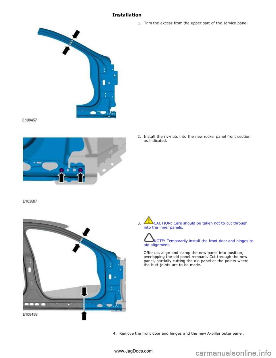
23.
24. Using the new panel for reference and allowing for an
overlap, cut the old panel at the point indicated, where the
lower butt joint is to be made.
NOTE: A drill bit suitable for drilling boron should be
used on the upper spot welds, as indicated.
Drill out the spot welds.
25. Separate the joints and remove the old panel, also releasing the NVH
components.
Page 2849 of 3039
Installation
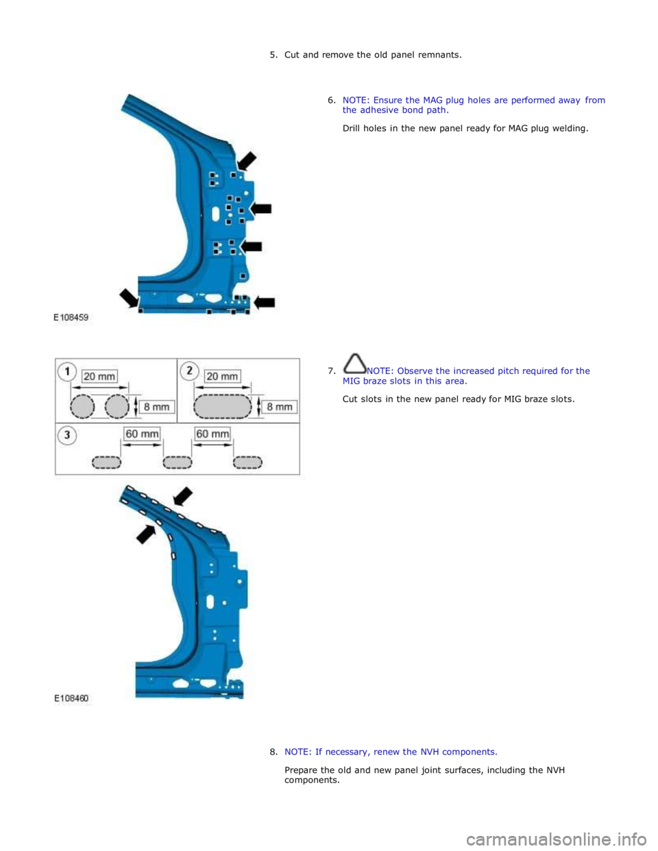
1. Trim the excess from the upper part of the service panel.
2. Install the riv-nuts into the new rocker panel front section
as indicated.
3. CAUTION: Care should be taken not to cut through
into the inner panels.
NOTE: Temporarily install the front door and hinges to
aid alignment.
Offer up, align and clamp the new panel into position,
overlapping the old panel remnant. Cut through the new
panel, partially cutting the old panel at the points where
the butt joints are to be made.
4. Remove the front door and hinges and the new A-pillar outer panel. www.JagDocs.com
Page 2850 of 3039
Trending: parking brake, tailgate, alarm, Oxygen sensor, Rear Drive Axle and Differential, Parking sensors, B100a 87
