JAGUAR XFR 2010 1.G Workshop Manual
XFR 2010 1.G
JAGUAR
JAGUAR
https://www.carmanualsonline.info/img/21/7642/w960_7642-0.png
JAGUAR XFR 2010 1.G Workshop Manual
Trending: sport mode, cruise control, B102, tow, maintenance schedule, radiator cap, b1009-62
Page 2821 of 3039
Lighting, Removal and Installation).
7. Remove the condenser core.
For additional information, refer to: Condenser Core - 2.7L Diesel
(412-03, Removal and Installation) /
Condenser Core - V6 3.0L Petrol (412-03 Air Conditioning, Removal and Installation) /
Condenser Core - 4.2L, Vehicles Without: Supercharger (412-03, Removal
and Installation) /
Condenser Core - 4.2L, Vehicles With: Supercharger (412-03, Removal
and Installation).
8. Remove the radiator.
For additional information, refer to: Radiator (303-03A, Removal and
Installation) /
Radiator (303-03B Engine Cooling - V6 3.0L Petrol, Removal and Installation) /
Radiator - Vehicles With: Supercharger (303-03C, Removal and
Installation) /
Radiator - Vehicles Without: Supercharger (303-03C, Removal and
Installation).
9. Remove the both hood latch panel braces.
10. Remove the cooling fan upper shroud.
11. Remove both crash sensors.
For additional information, refer to: Crash Sensor (501-20B Supplemental Restraint System, Removal and Installation).
12. Remove the both hood latches.
13. Remove the hood safety hook guide.
14. Remove both hood latch panel buffers.
15. Release and lay aside the hood latch panel wiring harness.
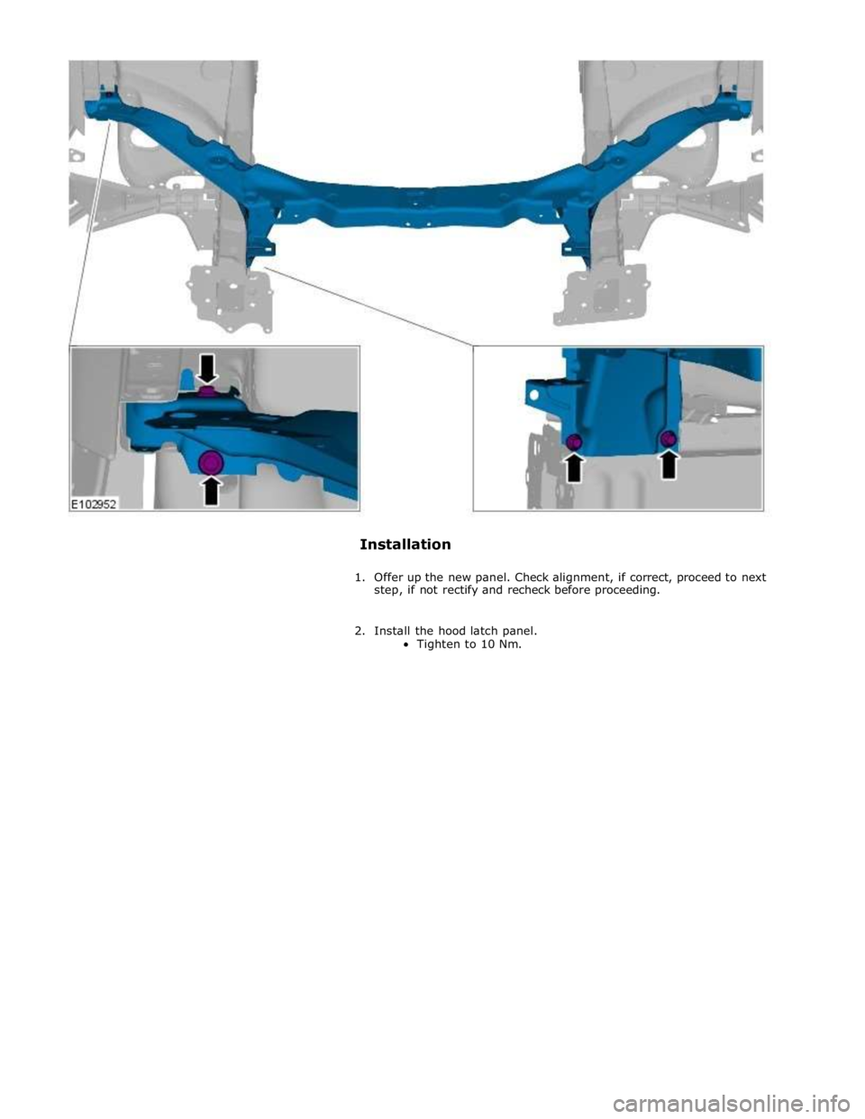
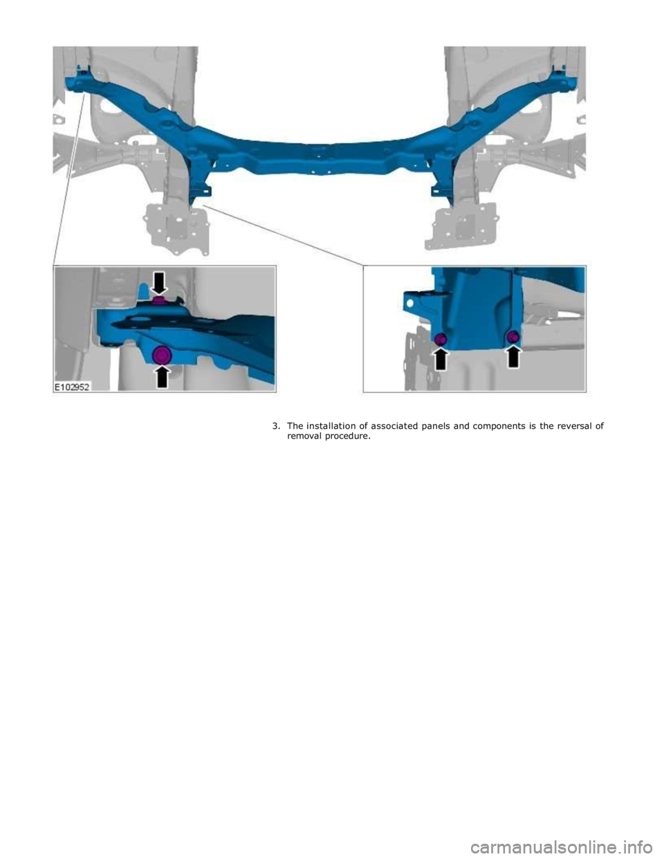
16. Remove the old panel.
Page 2822 of 3039
Page 2823 of 3039
Page 2824 of 3039
Published: 11-May-2011
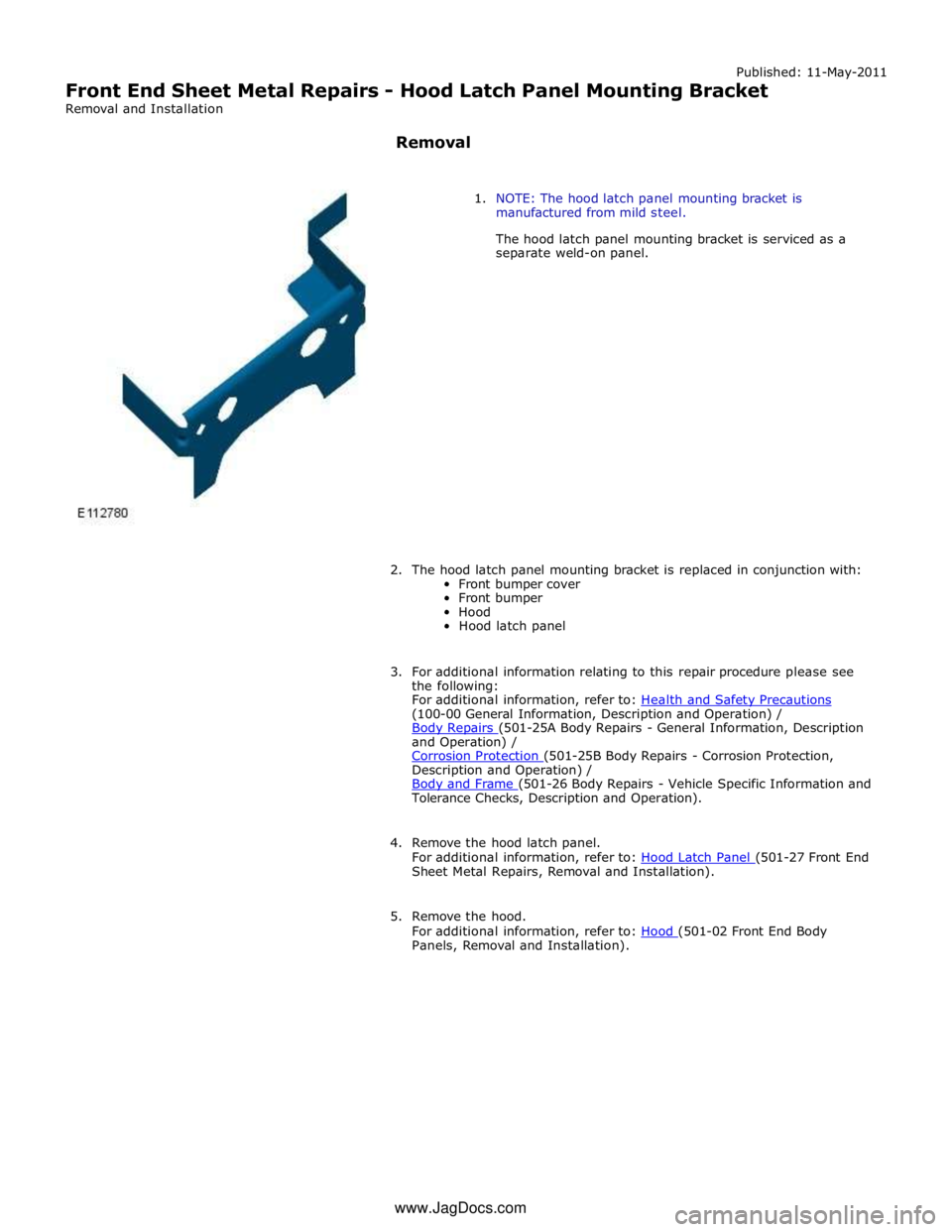
Front End Sheet Metal Repairs - Hood Latch Panel Mounting Bracket
Removal and Installation
Removal
1. NOTE: The hood latch panel mounting bracket is
manufactured from mild steel.
The hood latch panel mounting bracket is serviced as a
separate weld-on panel.
2. The hood latch panel mounting bracket is replaced in conjunction with:
Front bumper cover
Front bumper
Hood
Hood latch panel
3. For additional information relating to this repair procedure please see
the following:
For additional information, refer to: Health and Safety Precautions (100-00 General Information, Description and Operation) /
Body Repairs (501-25A Body Repairs - General Information, Description and Operation) /
Corrosion Protection (501-25B Body Repairs - Corrosion Protection, Description and Operation) /
Body and Frame (501-26 Body Repairs - Vehicle Specific Information and Tolerance Checks, Description and Operation).
4. Remove the hood latch panel.
For additional information, refer to: Hood Latch Panel (501-27 Front End Sheet Metal Repairs, Removal and Installation).
5. Remove the hood.
For additional information, refer to: Hood (501-02 Front End Body Panels, Removal and Installation). www.JagDocs.com
Page 2825 of 3039
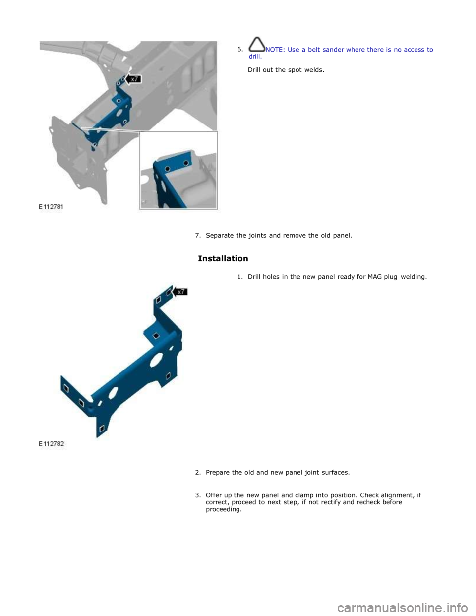
6. drill. NOTE: Use a belt sander where there is no access to
Drill out the spot welds.
7. Separate the joints and remove the old panel.
Installation
1. Drill holes in the new panel ready for MAG plug welding.
2. Prepare the old and new panel joint surfaces.
3. Offer up the new panel and clamp into position. Check alignment, if
correct, proceed to next step, if not rectify and recheck before
proceeding.
Page 2826 of 3039
Page 2827 of 3039
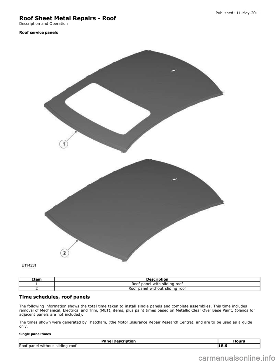
1 Roof panel with sliding roof 2 Roof panel without sliding roof Time schedules, roof panels
The following information shows the total time taken to install single panels and complete assemblies. This time includes
removal of Mechanical, Electrical and Trim, (MET), items, plus paint times based on Metallic Clear Over Base Paint, (blends for
adjacent panels are not included).
The times shown were generated by Thatcham, (the Motor Insurance Repair Research Centre), and are to be used as a guide
only.
Single panel times
Panel Description Hours Roof panel without sliding roof 18.6
Page 2828 of 3039
Published: 11-May-2011
Roof Sheet Metal Repairs - Roof Panel Vehicles With: Sliding Roof Opening
Panel
Removal and Installation
Removal
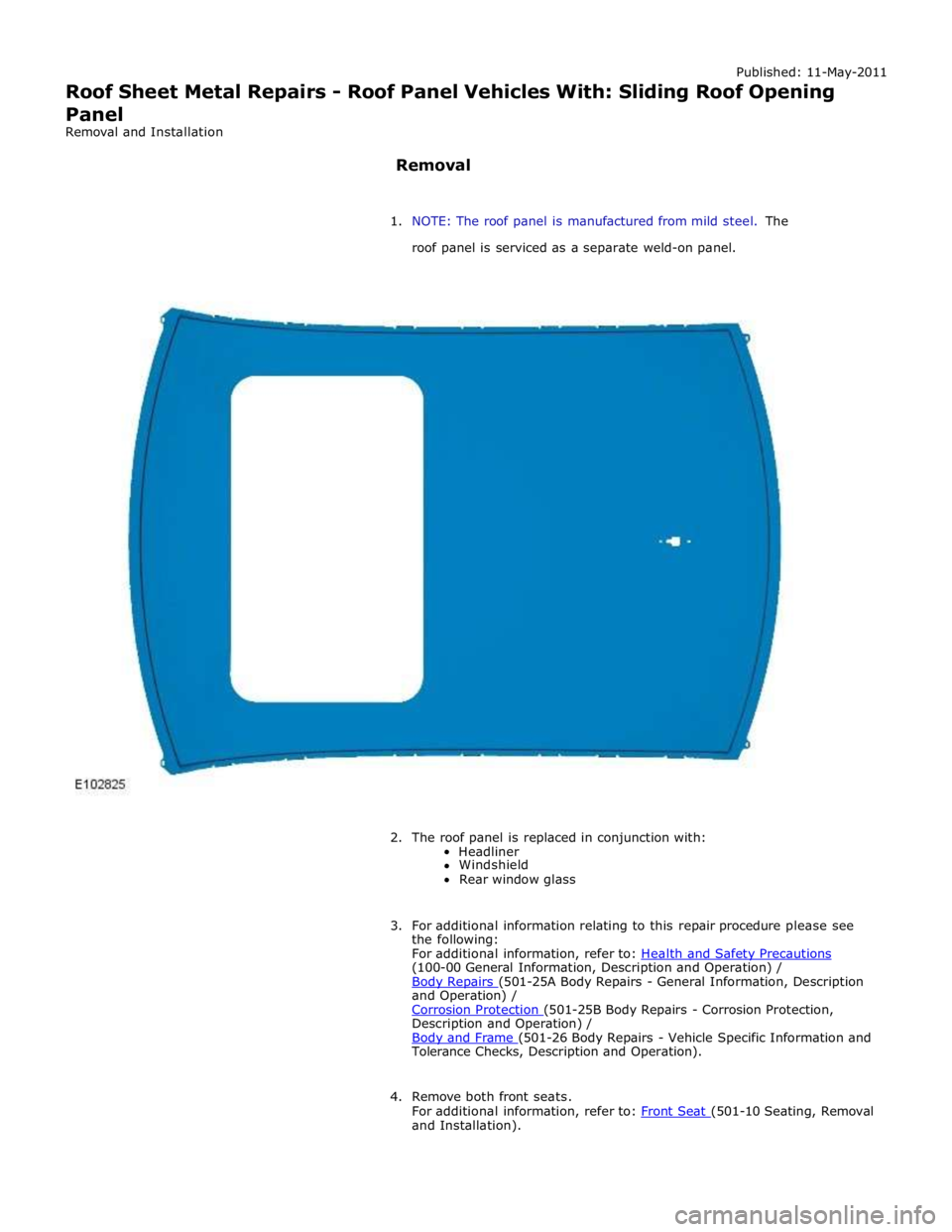
1. NOTE: The roof panel is manufactured from mild steel. The
roof panel is serviced as a separate weld-on panel.
2. The roof panel is replaced in conjunction with:
Headliner
Windshield
Rear window glass
3. For additional information relating to this repair procedure please see
the following:
For additional information, refer to: Health and Safety Precautions (100-00 General Information, Description and Operation) /
Body Repairs (501-25A Body Repairs - General Information, Description and Operation) /
Corrosion Protection (501-25B Body Repairs - Corrosion Protection, Description and Operation) /
Body and Frame (501-26 Body Repairs - Vehicle Specific Information and Tolerance Checks, Description and Operation).
4. Remove both front seats.
For additional information, refer to: Front Seat (501-10 Seating, Removal and Installation).
Page 2829 of 3039

(414-01 Battery, Mounting and Cables, General Procedures).
6. Disconnect the generator electrical connectors.
7. Remove the windshield glass.
For additional information, refer to: Windshield Glass (501-11 Glass, Frames and Mechanisms, Removal and Installation).
8. Remove the rear window glass.
For additional information, refer to: Rear Window Glass (501-11 Glass, Frames and Mechanisms, Removal and Installation).
9. Remove the roof opening panel frame.
For additional information, refer to: Roof Opening Panel Frame (501-17 Roof Opening Panel, Removal and Installation).
10. Remove the driver and passenger side front scuff plate trim panels.
For additional information, refer to: Front Scuff Plate Trim Panel (501-05 Interior Trim and Ornamentation, Removal and Installation).
11. Remove the driver and passenger side rear scuff plate trim panels.
For additional information, refer to: Rear Scuff Plate Trim Panel (501-05 Interior Trim and Ornamentation, Removal and Installation).
12. Remove the driver and passenger side air curtain modules.
For additional information, refer to: Side Air Curtain Module (501-20B Supplemental Restraint System, Removal and Installation).
13. Remove the rear seat backrest.
14. Remove the driver and passenger side rear safety belt retractors.
For additional information, refer to: Rear Safety Belt Retractor (501-20A Safety Belt System, Removal and Installation).
15. Remove the rear center safety belt retractor.
For additional information, refer to: Rear Center Safety Belt Retractor (501-20A Safety Belt System, Removal and Installation).
16. Remove the driver and passenger side RF filters.
17. Remove the diversity antenna module.
18. Remove the antenna.
For additional information, refer to: Navigation System Antenna (419-07 Navigation System, Removal and Installation).
19. Release and position the roof wiring harnesses to one side
20. Position the roof opening panel front and rear drain hoses to one side.
21. Remove the driver and passenger side roof mouldings.
22. Drill out the spot welds.
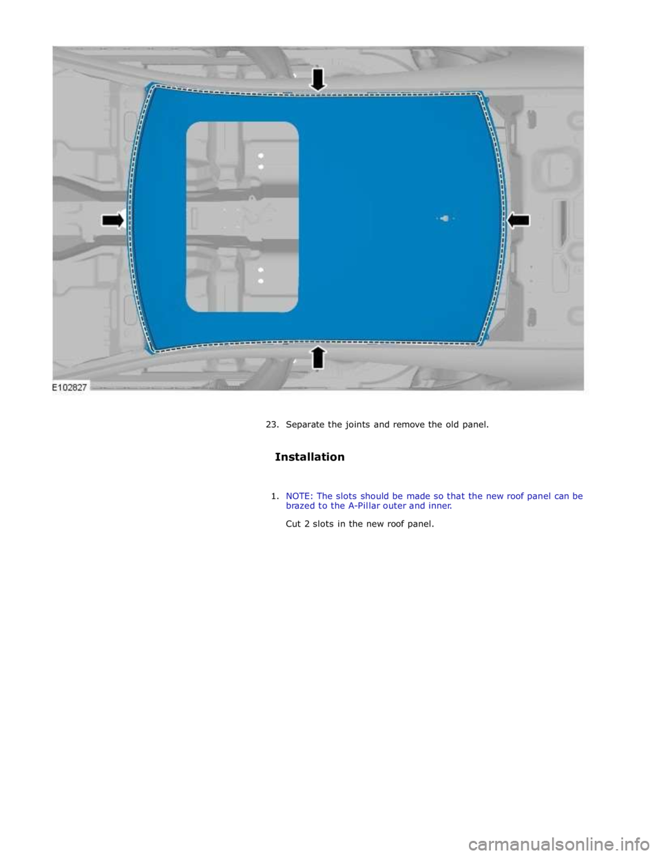
www.JagDocs.com
Page 2830 of 3039
Trending: catalytic converter, diagram, spare wheel, Throttle, electrical wiring diagrams, Spark plugs, airbag disable

