JAGUAR XFR 2010 1.G Workshop Manual
XFR 2010 1.G
JAGUAR
JAGUAR
https://www.carmanualsonline.info/img/21/7642/w960_7642-0.png
JAGUAR XFR 2010 1.G Workshop Manual
Trending: flat tire, Pedestrian protection, srs, lights, seat recline motor, Timing, dimensions
Page 2901 of 3039
Page 2902 of 3039
(100-00 General Information, Description and Operation) /
Body Repairs (501-25A Body Repairs - General Information, Description and Operation) /
Corrosion Protection (501-25B Body Repairs - Corrosion Protection, Description and Operation) /
Body and Frame (501-26 Body Repairs - Vehicle Specific Information and Tolerance Checks, Description and Operation).
Page 2903 of 3039

and Installation).
5. Disconnect the generator electrical connectors.
6. Remove the right-hand and left-hand front scuff plate trim panels.
For additional information, refer to: Front Scuff Plate Trim Panel (501-05 Interior Trim and Ornamentation, Removal and Installation).
7. Remove the front and rear door weatherstrips.
8. Remove the right-hand and left-hand rear scuff plate trim panels.
For additional information, refer to: Rear Scuff Plate Trim Panel (501-05 Interior Trim and Ornamentation, Removal and Installation).
9. Remove the headliner.
For additional information, refer to: Headliner (501-05 Interior Trim and Ornamentation, Removal and Installation).
10. Remove the side air curtain module.
For additional information, refer to: Side Air Curtain Module (501-20B Supplemental Restraint System, Removal and Installation).
11. Remove the rear seat cushion.
For additional information, refer to: Rear Seat Cushion (501-10 Seating, Removal and Installation).
12. Remove the rear seat backrest.
13. Release and position the roof wiring harness to one side.
14. Remove the roof moulding.
15. Remove the cowl side trim panel.
For additional information, refer to: Cowl Side Trim Panel (501-05 Interior Trim and Ornamentation, Removal and Installation).
16. Remove the front safety belt retractor.
For additional information, refer to: Front Safety Belt Retractor (501-20A Safety Belt System, Removal and Installation).
17. Remove the B-pillar side impact sensor.
For additional information, refer to: B-Pillar Side Impact Sensor (501-20B Supplemental Restraint System, Removal and Installation).
18. Remove the C-pillar side impact sensor.
For additional information, refer to: C-Pillar Side Impact Sensor (501-20B Supplemental Restraint System, Removal and Installation).
19. Release and position the floor covering to one side.
20. Release and position the inner rocker panel wiring harness to one side.
21. Remove the rear wheel and tire.
For additional information, refer to: Wheel and Tire (204-04 Wheels and
Page 2904 of 3039
Tires, Removal and Installation).
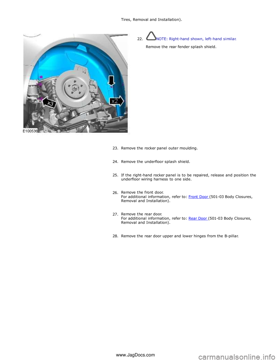
22. NOTE: Right-hand shown, left-hand similar.
Remove the rear fender splash shield.
23. Remove the rocker panel outer moulding.
24. Remove the underfloor splash shield.
25. If the right-hand rocker panel is to be repaired, release and position the
underfloor wiring harness to one side.
26. Remove the front door.
For additional information, refer to: Front Door (501-03 Body Closures, Removal and Installation).
27. Remove the rear door.
For additional information, refer to: Rear Door (501-03 Body Closures, Removal and Installation).
28. Remove the rear door upper and lower hinges from the B-pillar. www.JagDocs.com
Page 2905 of 3039
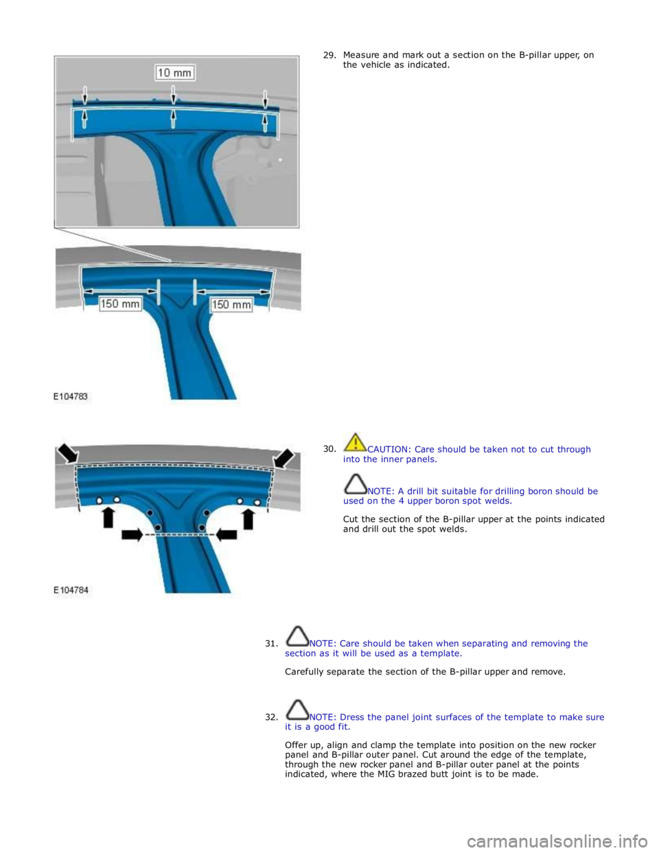
29.
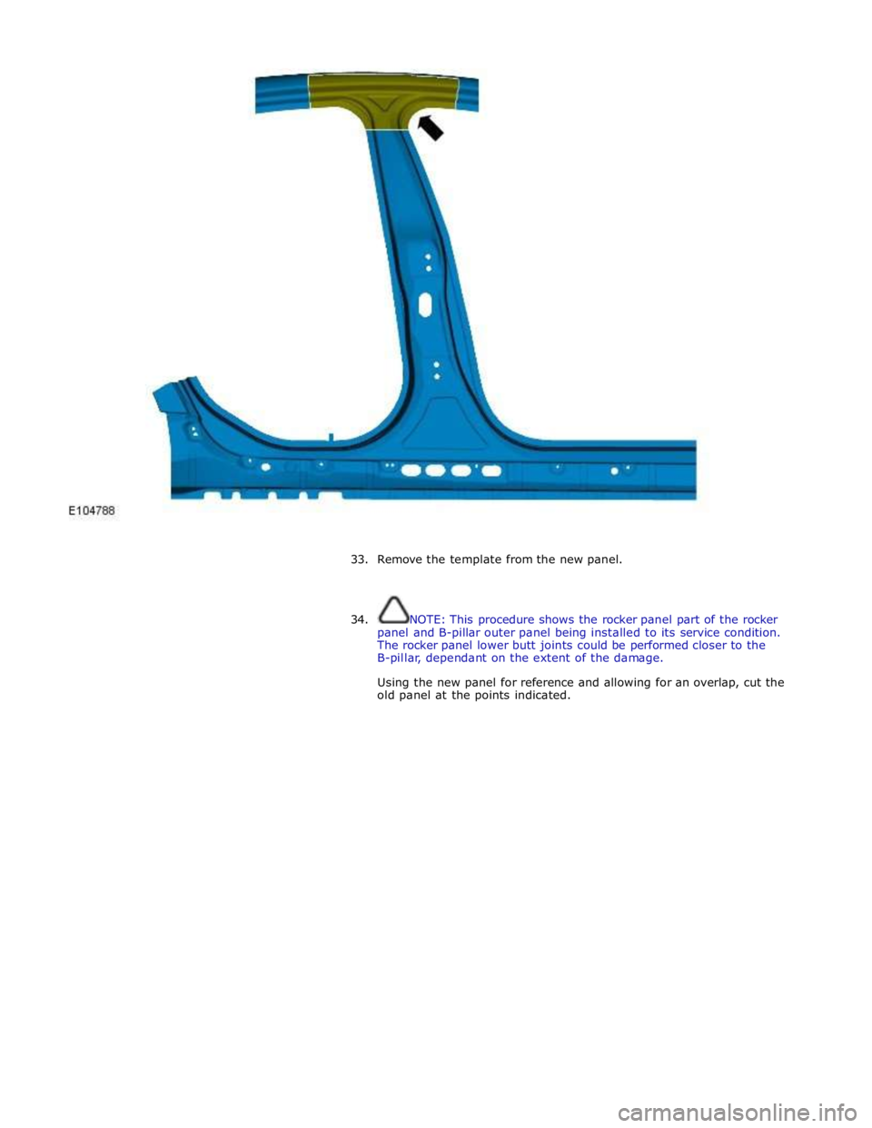
30. Measure and mark out a section on the B-pillar upper, on
the vehicle as indicated.
CAUTION: Care should be taken not to cut through
into the inner panels.
NOTE: A drill bit suitable for drilling boron should be
used on the 4 upper boron spot welds.
Cut the section of the B-pillar upper at the points indicated
and drill out the spot welds.
31.
NOTE: Care should be taken when separating and removing the
section as it will be used as a template.
Carefully separate the section of the B-pillar upper and remove.
32. NOTE: Dress the panel joint surfaces of the template to make sure
it is a good fit.
Offer up, align and clamp the template into position on the new rocker
panel and B-pillar outer panel. Cut around the edge of the template,
through the new rocker panel and B-pillar outer panel at the points
indicated, where the MIG brazed butt joint is to be made.
Page 2906 of 3039
33. Remove the template from the new panel.
34. NOTE: This procedure shows the rocker panel part of the rocker
panel and B-pillar outer panel being installed to its service condition.
The rocker panel lower butt joints could be performed closer to the
B-pillar, dependant on the extent of the damage.
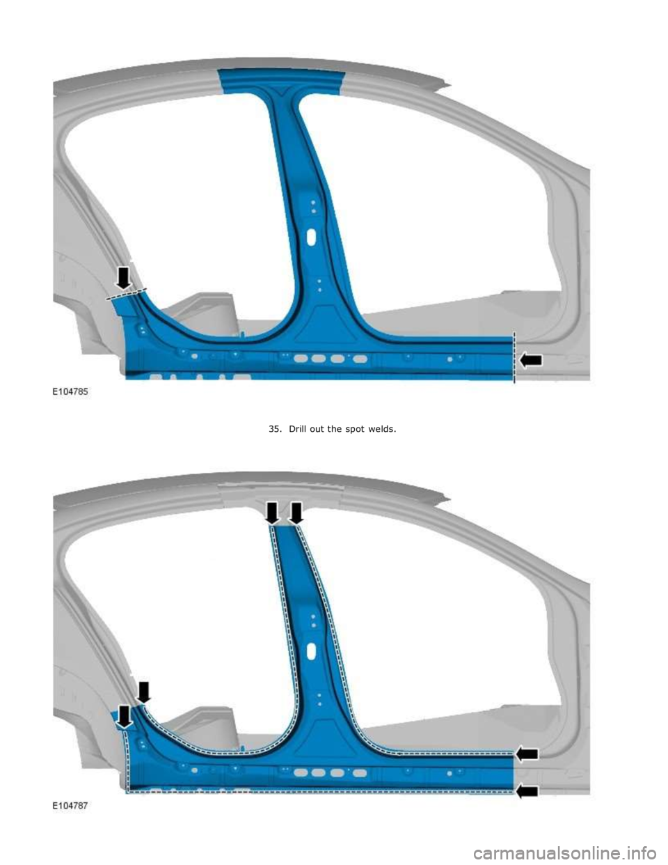
Using the new panel for reference and allowing for an overlap, cut the
old panel at the points indicated.
Page 2907 of 3039
Page 2908 of 3039
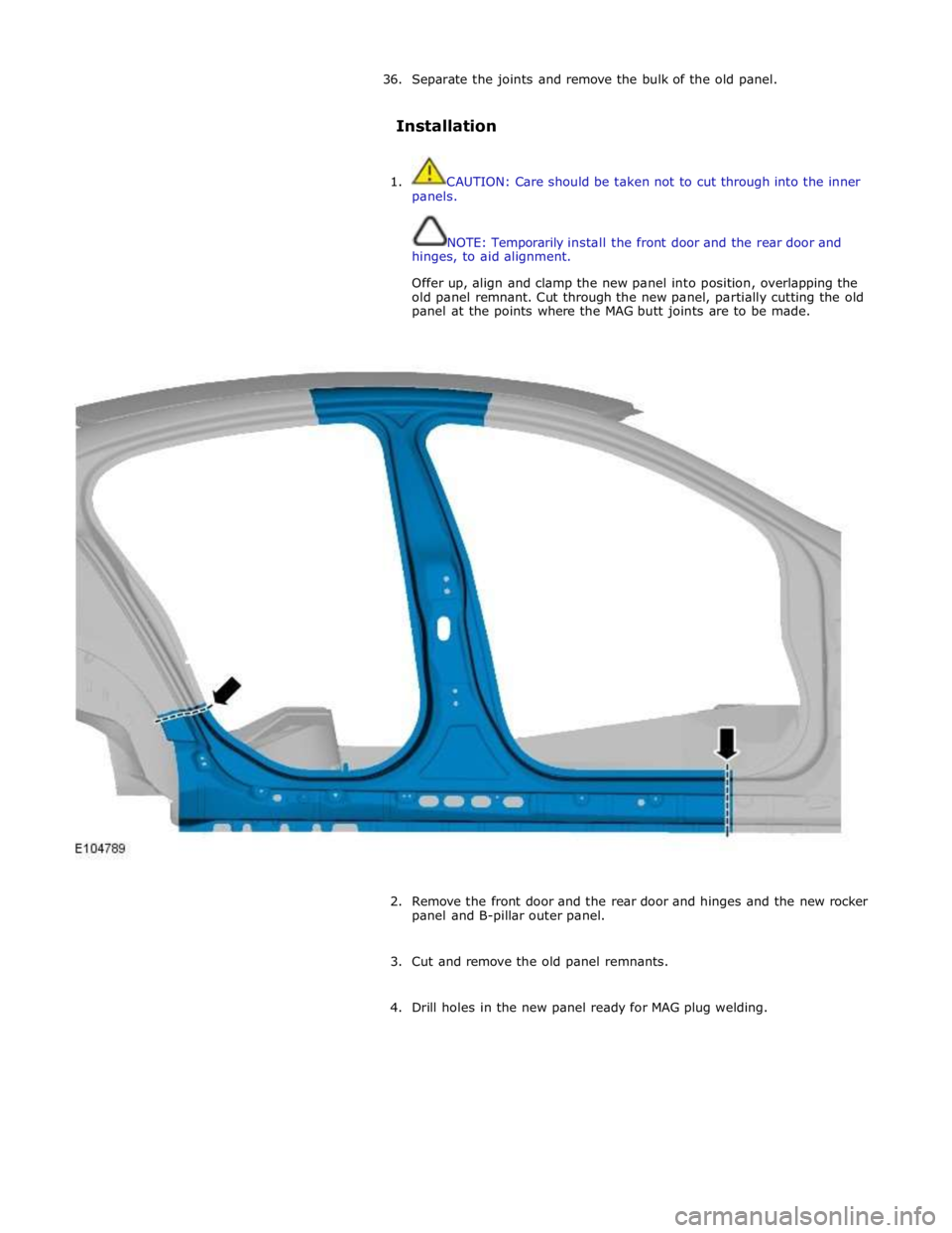
36. Separate the joints and remove the bulk of the old panel.
Installation
1. CAUTION: Care should be taken not to cut through into the inner
panels.
NOTE: Temporarily install the front door and the rear door and
hinges, to aid alignment.
Offer up, align and clamp the new panel into position, overlapping the
old panel remnant. Cut through the new panel, partially cutting the old
panel at the points where the MAG butt joints are to be made.
2. Remove the front door and the rear door and hinges and the new rocker
panel and B-pillar outer panel.
3. Cut and remove the old panel remnants.
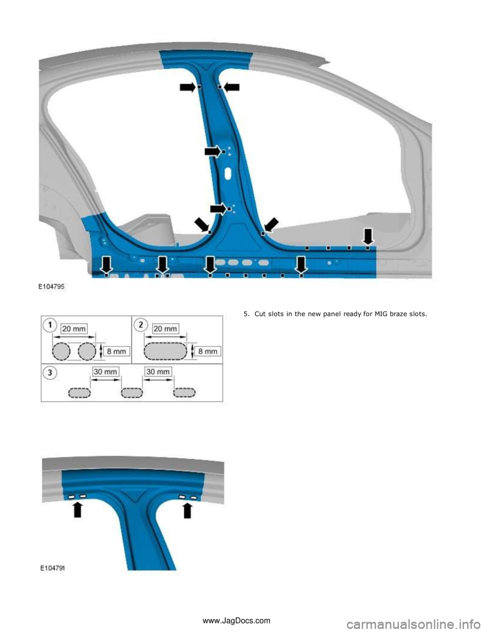
4. Drill holes in the new panel ready for MAG plug welding.
Page 2909 of 3039
Page 2910 of 3039
6. NOTE: If necessary, renew the NVH component.
Prepare the old and new panel joint surfaces, including the NVH
component.
7. NOTE: Temporarily install the front door and the rear door and
hinges, to aid alignment.
Offer up the new panel and clamp into position. Check alignment, if
correct, proceed to next step, if not, rectify and recheck before
proceeding.
8. Remove the front door and the rear door and hinges and the new rocker
panel and B-pillar outer panel.
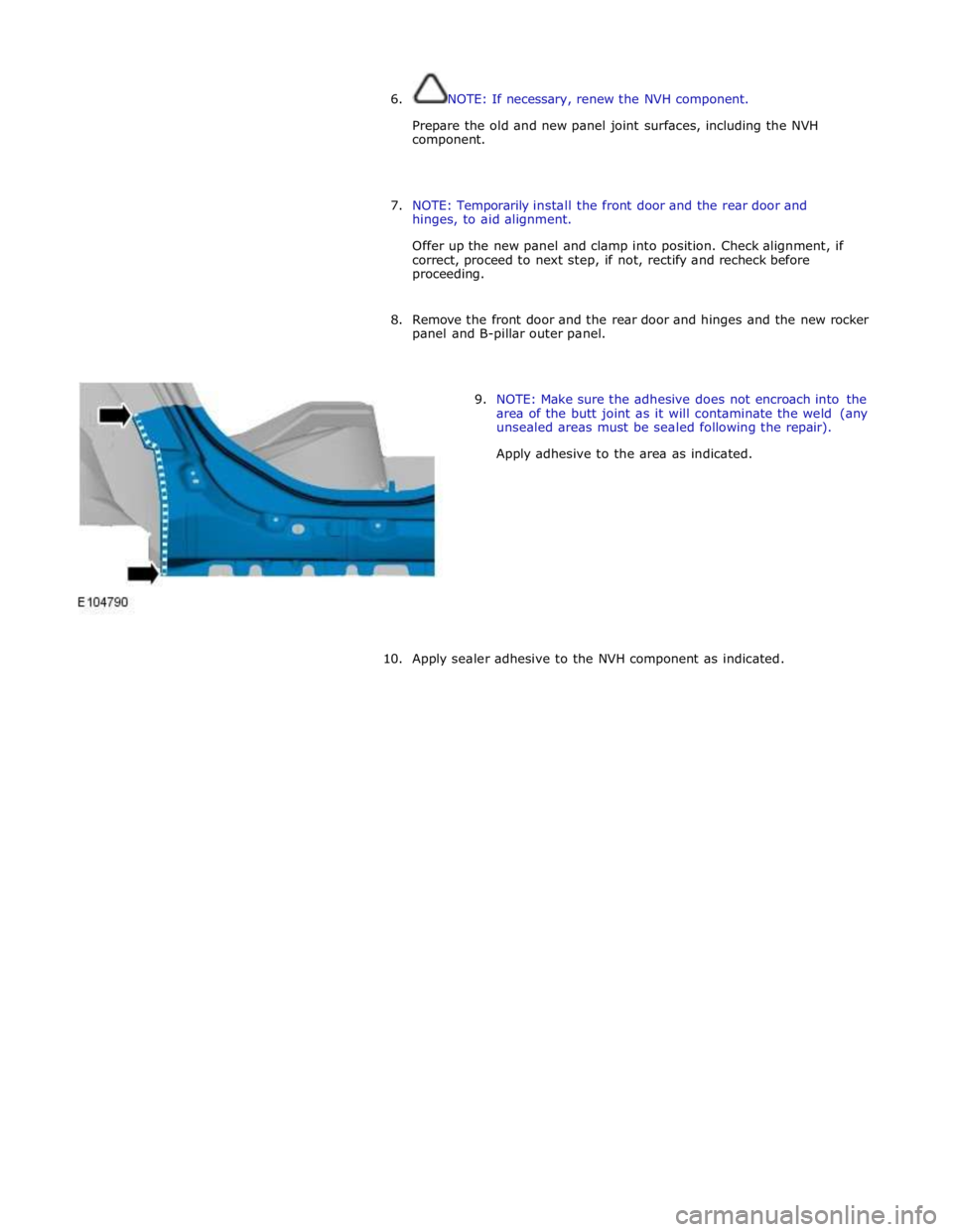
9. NOTE: Make sure the adhesive does not encroach into the
area of the butt joint as it will contaminate the weld (any
unsealed areas must be sealed following the repair).
Apply adhesive to the area as indicated.
10. Apply sealer adhesive to the NVH component as indicated.
Trending: oil capacities, B100d-64, jacking points, height, park assist, Rear Drive, ect sensor electrical diagram
