box JAGUAR XFR 2010 1.G Repair Manual
[x] Cancel search | Manufacturer: JAGUAR, Model Year: 2010, Model line: XFR, Model: JAGUAR XFR 2010 1.GPages: 3039, PDF Size: 58.49 MB
Page 1125 of 3039
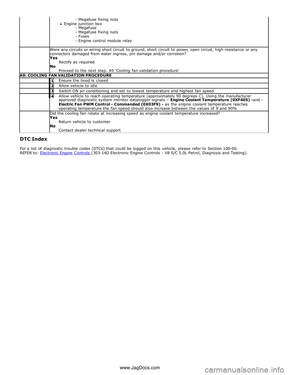
- Megafuse fixing nuts
Engine junction box
- Megafuse
- Megafuse fixing nuts
- Fuses
- Engine control module relay Were any circuits or wiring short circuit to ground, short circuit to power, open circuit, high resistance or any
connectors damaged from water ingress, pin damage and/or corrosion?
Yes
Rectify as required
No
Proceed to the next step. A9 'Cooling fan validation procedure' A9: COOLING FAN VALIDATION PROCEDURE 1 Ensure the hood is closed 2 Allow vehicle to idle 3 Switch ON air conditioning and set to lowest temperature and highest fan speed 4 Allow vehicle to reach operating temperature (approximately 90 degrees C). Using the manufacturer approved diagnostic system monitor datalogger signals – Engine Coolant Temperature (0XF405) -and -
Electric Fan PWM Control - Commanded (0X03F9) - as the engine coolant temperature reaches
operating temperature the fan speed should also increase between the values of 9 and 90% Did the cooling fan rotate at increasing speed as engine coolant temperature increased?
Yes
Return vehicle to customer
No
Contact dealer technical support DTC Index
For a list of diagnostic trouble codes (DTCs) that could be logged on this vehicle, please refer to Section 100-00.
REFER to: Electronic Engine Controls (303-14D Electronic Engine Controls - V8 S/C 5.0L Petrol, Diagnosis and Testing). www.JagDocs.com
Page 1169 of 3039
Published: 11-May-2011
Supercharger Cooling - V8 S/C 5.0L Petrol - Supercharger Cooling - System
Operation and Component Description
Description and Operation
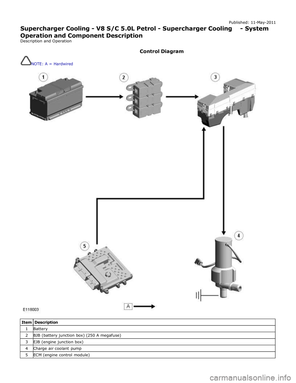
Control Diagram
NOTE: A = Hardwired
Item Description 1 Battery 2 BJB (battery junction box) (250 A megafuse) 3 EJB (engine junction box) 4 Charge air coolant pump 5 ECM (engine control module)
Page 1170 of 3039
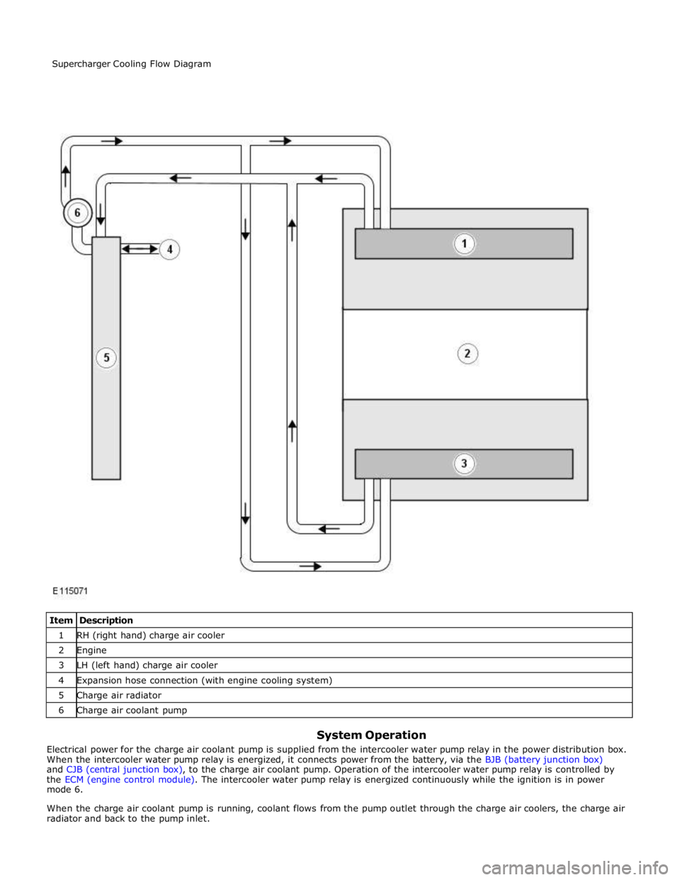
1 RH (right hand) charge air cooler 2 Engine 3 LH (left hand) charge air cooler 4 Expansion hose connection (with engine cooling system) 5 Charge air radiator 6 Charge air coolant pump
System Operation
Electrical power for the charge air coolant pump is supplied from the intercooler water pump relay in the power distribution box.
When the intercooler water pump relay is energized, it connects power from the battery, via the BJB (battery junction box)
and CJB (central junction box), to the charge air coolant pump. Operation of the intercooler water pump relay is controlled by
the ECM (engine control module). The intercooler water pump relay is energized continuously while the ignition is in power
mode 6.
When the charge air coolant pump is running, coolant flows from the pump outlet through the charge air coolers, the charge air
radiator and back to the pump inlet. Supercharger Cooling Flow Diagram
Page 1180 of 3039
Published: 15-Mar-2013
Fuel Charging and Controls - V8 S/C 5.0L Petrol - Fuel Charging and Controls
- System Operation and Component Description
Description and Operation
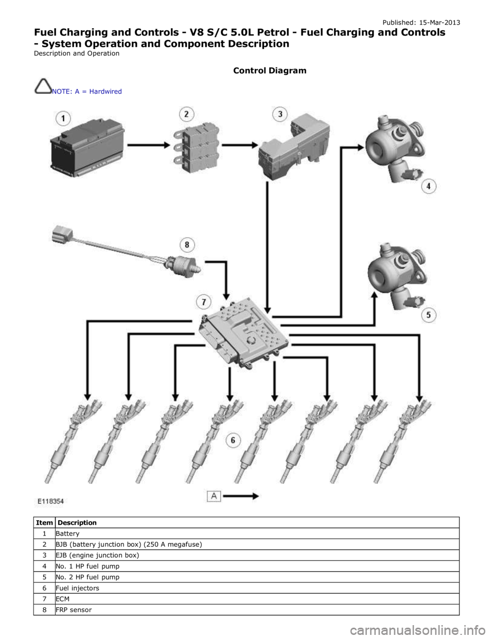
Control Diagram
NOTE: A = Hardwired
Item Description 1 Battery 2 BJB (battery junction box) (250 A megafuse) 3 EJB (engine junction box) 4 No. 1 HP fuel pump 5 No. 2 HP fuel pump 6 Fuel injectors 7 ECM 8 FRP sensor
Page 1262 of 3039
When the ECM receives a crank request, it energizes the starter relay in the EJB (engine junction box). The energized starter relay supplies 12 V power (fed via the 250 A megafuse in the BJB (battery junction box)) to energize the pull-in coil of the
starter solenoid. Once activated, the pull-in coil engages the solenoid plunger, which engages the pinion with the ring gear.
The plunger then closes the solenoid circuit, feeding power from the 400 A megafuse in the BJB to the starter motor.
Page 1263 of 3039
Published: 11-May-2011
Starting System - V8 5.0L Petrol/V8 S/C 5.0L Petrol - Starting System
Diagnosis and Testing
Principles of Operation
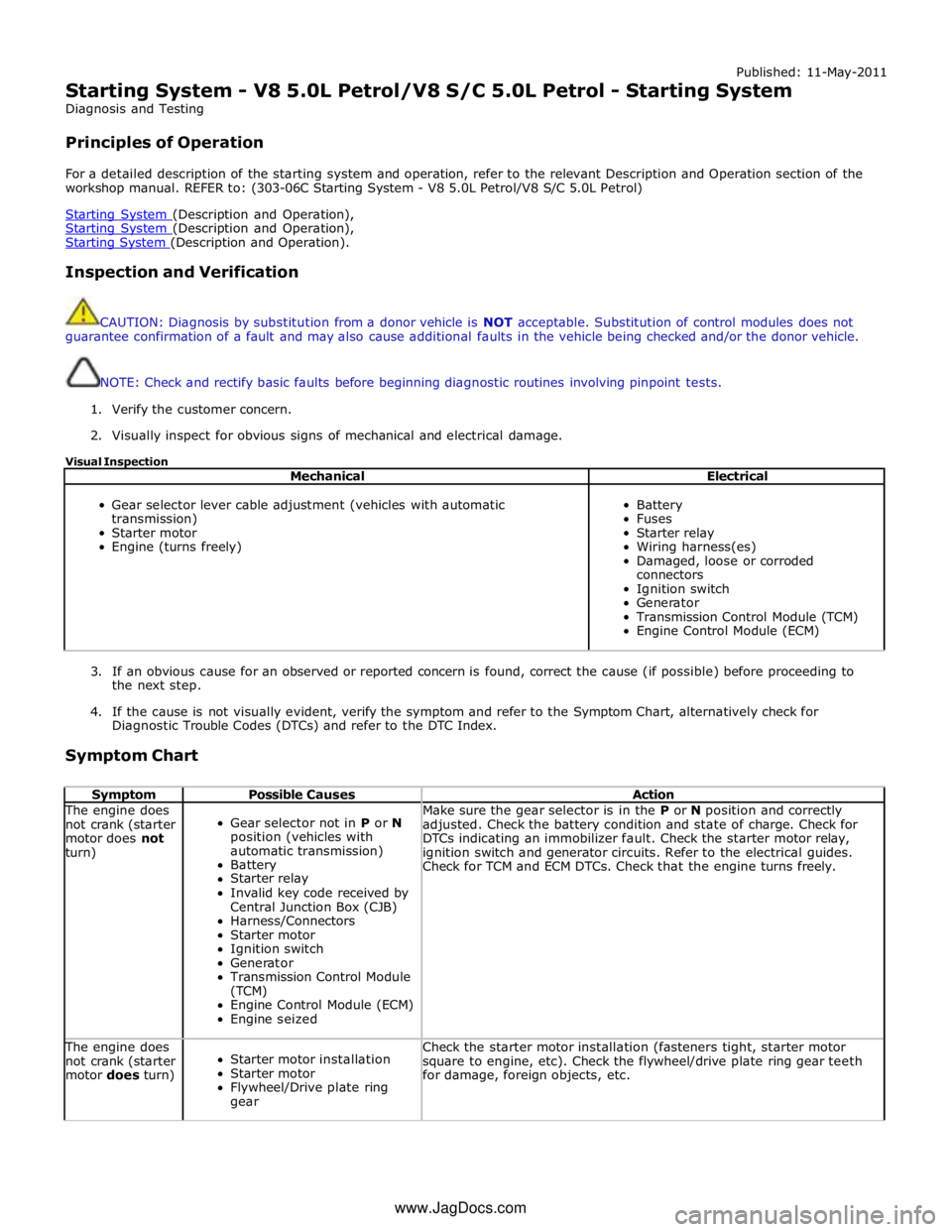
For a detailed description of the starting system and operation, refer to the relevant Description and Operation section of the
workshop manual. REFER to: (303-06C Starting System - V8 5.0L Petrol/V8 S/C 5.0L Petrol)
Starting System (Description and Operation), Starting System (Description and Operation), Starting System (Description and Operation).
Inspection and Verification
CAUTION: Diagnosis by substitution from a donor vehicle is NOT acceptable. Substitution of control modules does not
guarantee confirmation of a fault and may also cause additional faults in the vehicle being checked and/or the donor vehicle.
NOTE: Check and rectify basic faults before beginning diagnostic routines involving pinpoint tests.
1. Verify the customer concern.
2. Visually inspect for obvious signs of mechanical and electrical damage.
Visual Inspection
Mechanical Electrical
Gear selector lever cable adjustment (vehicles with automatic
transmission)
Starter motor
Engine (turns freely)
Battery
Fuses
Starter relay
Wiring harness(es)
Damaged, loose or corroded
connectors
Ignition switch
Generator
Transmission Control Module (TCM)
Engine Control Module (ECM)
3. If an obvious cause for an observed or reported concern is found, correct the cause (if possible) before proceeding to
the next step.
4. If the cause is not visually evident, verify the symptom and refer to the Symptom Chart, alternatively check for
Diagnostic Trouble Codes (DTCs) and refer to the DTC Index.
Symptom Chart
Symptom Possible Causes Action The engine does
not crank (starter
motor does not
turn)
Gear selector not in P or N
position (vehicles with
automatic transmission)
Battery
Starter relay
Invalid key code received by
Central Junction Box (CJB)
Harness/Connectors
Starter motor
Ignition switch
Generator
Transmission Control Module
(TCM)
Engine Control Module (ECM)
Engine seized Make sure the gear selector is in the P or N position and correctly
adjusted. Check the battery condition and state of charge. Check for
DTCs indicating an immobilizer fault. Check the starter motor relay,
ignition switch and generator circuits. Refer to the electrical guides.
Check for TCM and ECM DTCs. Check that the engine turns freely. The engine does
not crank (starter
motor does turn)
Starter motor installation
Starter motor
Flywheel/Drive plate ring
gear Check the starter motor installation (fasteners tight, starter motor
square to engine, etc). Check the flywheel/drive plate ring gear teeth
for damage, foreign objects, etc. www.JagDocs.com
Page 1273 of 3039
Published: 11-May-2011
Engine Ignition - V8 5.0L Petrol/V8 S/C 5.0L Petrol - Engine Ignition - System Operation and Component Description
Description and Operation
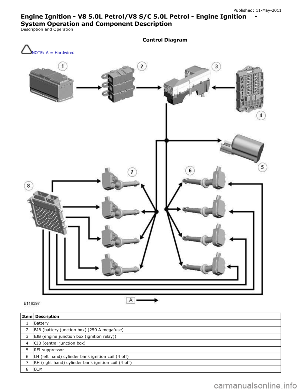
Control Diagram
NOTE: A = Hardwired
Item Description 1 Battery 2 BJB (battery junction box) (250 A megafuse) 3 EJB (engine junction box (ignition relay)) 4 CJB (central junction box) 5 RFI suppressor 6 LH (left hand) cylinder bank ignition coil (4 off) 7 RH (right hand) cylinder bank ignition coil (4 off) 8 ECM
Page 1274 of 3039
GENERAL System Operation
The ignition coils are supplied with electrical power from the battery via a 250 A megafuse in the BJB (battery junction box)
and the ignition relay in the EJB (engine junction box). The control signal for the ignition relay is supplied by the CJB (central
junction box).
The ECM (engine control module) sends a separate signal to each ignition coil to trigger the power stage switching. The ECM calculates the dwell time from the battery voltage and engine speed, to ensure a constant energy level is produced in the
secondary coil each time the power stage is switched. This ensures sufficient spark energy is available without excessive
primary current flow, which avoids overheating and damage to the ignition coils.
The ECM calculates the ignition timing for individual cylinders from: Engine speed
Camshaft position
Engine load
Engine temperature
The knock control function
The shift control function
The idle speed control function.
IGNITION COILS Component Description
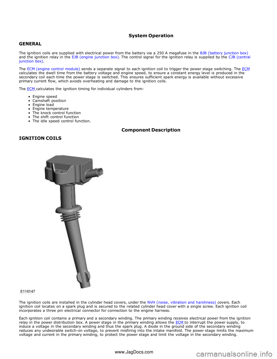
The ignition coils are installed in the cylinder head covers, under the NVH (noise, vibration and harshness) covers. Each
ignition coil locates on a spark plug and is secured to the related cylinder head cover with a single screw. Each ignition coil
incorporates a three pin electrical connector for connection to the engine harness.
Each ignition coil contains a primary and a secondary winding. The primary winding receives electrical power from the ignition
relay in the power distribution box. A power stage in the primary winding allows the ECM to interrupt the power supply, to induce a voltage in the secondary winding and thus the spark plug. A diode in the ground side of the secondary winding
reduces any undesirable switch-on voltage, to prevent misfiring into the intake manifold. The power stage limits the maximum
voltage and current in the primary winding, to protect the power stage and limit the voltage in the secondary winding. www.JagDocs.com
Page 1288 of 3039

Published: 11-May-2011
Intake Air Distribution and Filtering - V8 S/C 5.0L Petrol - Intake Air
Distribution and Filtering - System Operation and Component Description
Description and Operation
Control Diagram
NOTE: A = Hardwired
Item Description 1 Battery 2 BJB (battery junction box) (250 A megafuse) 3 EJB (engine junction box) (EMS high current relay) 4 Tuning valve 5 ECM (engine control module)
Page 1289 of 3039

SUPERCHARGER System Operation
At closed or partially open throttle positions, the bypass valve is fully open, allowing a flow of air from the SC (supercharger)
outlet back to the inlet side. This results in little or no pressure increase across the SC. Progressive opening of the throttle reduces the depression downstream of the electric throttle. This is sensed by the pneumatic actuator, which moves to close
the bypass valve. As the bypass valve closes there is a corresponding increase in the outlet pressure from the SC, which increases engine power output.
NOISE FEEDBACK SYSTEM
Sound waves from the RH (right-hand) intake manifold are filtered by the calibrated orifice in the inlet pipe connection on the
symposer. The sound waves make the paddle oscillate and generate pulsations in the outlet chambers. When the pneumatic
valve is open, the pulsations are transmitted through the outlet pipe and feedback tube to the resonator in the passenger
compartment.
The tuning valve of the noise feedback system receives a power feed from the power distribution box and is connected to
ground through the ECM (engine control module). At lower engine loads and speeds the ECM keeps the ground open circuit and the tuning valve is de-energized closed. Atmospheric pressure is sensed at the pneumatic valve through the vent cap on the
tuning valve, which keeps the pneumatic valve closed and prevents sound from the symposer entering the feedback system.
At higher engine loads and speeds the ECM connects the tuning valve to ground. The tuning valve energizes, blanks off the atmospheric vent and opens the vacuum line between the brake vacuum system and the pneumatic valve. The depression in
the brake vacuum system is sensed at the pneumatic valve, which opens and allows sound from the symposer into the
feedback system.
The status of the pneumatic valve at various engine loads and speeds is given below:
Pneumatic Valve Status
NOTE: Values are for valve opening with increasing engine load and speed. Deduct 0.05 g/rev and 50 rev/min for valve
closing with decreasing engine load and speed.
Engine Load: g/rev Engine Speed: rev/min 0 500 1000 2500 3000 4000 5800 6500 1.30 Closed Closed Closed Closed Closed Closed Closed Closed 1.35 Closed Closed Closed Closed Closed Closed Closed Closed 1.40 Closed Closed Closed Closed Closed Closed Closed Open 1.60 Closed Closed Closed Closed Closed Closed Closed Open 1.80 Closed Closed Closed Closed Closed Closed Closed Open 2.50 Closed Closed Closed Closed Closed Open Open Open 3.00 Closed Closed Closed Closed Closed Open Open Open 3.50 Closed Closed Closed Open Open Open Open Open