box JAGUAR XFR 2010 1.G Manual PDF
[x] Cancel search | Manufacturer: JAGUAR, Model Year: 2010, Model line: XFR, Model: JAGUAR XFR 2010 1.GPages: 3039, PDF Size: 58.49 MB
Page 1358 of 3039
Published: 11-May-2011
Electronic Engine Controls - V8 S/C 5.0L Petrol - Electronic Engine Controls - System Operation and Component Description
Description and Operation
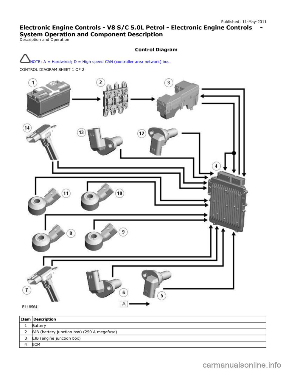
Control Diagram
NOTE: A = Hardwired; D = High speed CAN (controller area network) bus.
CONTROL DIAGRAM SHEET 1 OF 2
Item Description 1 Battery 2 BJB (battery junction box) (250 A megafuse) 3 EJB (engine junction box) 4 ECM
Page 1366 of 3039
the period of rich to lean and lean to rich switching monitors the response rate of the upstream sensors.
Diagnosis of electrical faults is continually monitored in both the upstream and downstream sensors. This is achieved by
checking the signal against maximum and minimum threshold, for open and short circuit conditions.
If a heated oxygen sensor fails:
The ECM defaults to open loop fueling for the related cylinder bank The CO (carbon monoxide) and emissions content of the exhaust gases increases
The exhaust smells of rotten eggs (hydrogen sulphide).
With a failed heated oxygen sensor, the engine will suffer from unstable operation and reduced performance.
ACCELERATOR PEDAL POSITION SENSOR
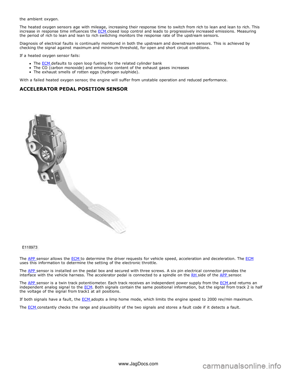
The APP sensor allows the ECM to determine the driver requests for vehicle speed, acceleration and deceleration. The ECM uses this information to determine the setting of the electronic throttle.
The APP sensor is installed on the pedal box and secured with three screws. A six pin electrical connector provides the interface with the vehicle harness. The accelerator pedal is connected to a spindle on the RH side of the APP sensor.
The APP sensor is a twin track potentiometer. Each track receives an independent power supply from the ECM and returns an independent analog signal to the ECM. Both signals contain the same positional information, but the signal from track 2 is half the voltage of the signal from track1 at all positions.
If both signals have a fault, the ECM adopts a limp home mode, which limits the engine speed to 2000 rev/min maximum. The ECM constantly checks the range and plausibility of the two signals and stores a fault code if it detects a fault. www.JagDocs.com
Page 1368 of 3039

(engine junction box).
When the ignition is turned on, battery voltage is applied to the ignition sense input. The ECM then starts its power up routines and energizes the main relay.
When the ignition is turned off, the ECM maintains its powered up state while it conducts the power down routines (up to 20 minutes in extreme cases, when cooling fans are required) and on completion will turn off the main relay.
Page 1373 of 3039

DTC Description Possible Causes Action B10AC-81
Cruise Control Switch -
invalid serial data received
The Engine Control Module
(ECM) has received an invalid
command from the steering
wheel switch pack Clear the DTC and press all the steering wheel
switches, re-check for DTCs. Refer to the
electrical circuit diagrams and check the Cruise
control switch circuit for open circuit, short to
power, short to ground, disconnected. Check
and install a new Steering Wheel Module (SWM) as required. B10AC-82 Cruise Control Switch - alive / sequence counter incorrect / not updated
Cruise Buttons alive counter is
not incrementing. Which
suggests that the LIN bus is
faulty
Steering Wheel Module (SWM) is
not connected
Steering Wheel Module (SWM)
failure Refer to the electrical circuit diagrams and
check the Cruise control switch circuit for open
circuit, short to power, short to ground,
disconnected. Check and install a new Steering
Wheel Module (SWM) as required. B10AC-83
Cruise Control Switch - value
of signal protection
calculation incorrect
Cruise buttons checksum
incorrect, incorrect cruise
switches fitted to vehicle Check and install new cruise switches as
required. B10AC-96
Cruise Control Switch -
component internal failure
Cruise control switch circuit,
open circuit, short to power,
short to ground, disconnected
Cruise Control Switch failure
Steering Wheel Module (SWM)
failure Check for related DTCs in other Central
Junction Box (CJB)s. Refer to the electrical
circuit diagrams and check the Cruise control
switch circuit for open circuit, short to power,
short to ground, disconnected. Check and
install a new cruise control switch as required.
Check and install a new Steering Wheel
Module (SWM) as required. B10FF-68
Ignition Control - Event
information
Spark plug(s) fault
Wiring harness fault
Ignition coil(s) fault Refer to repair manual and check spark plug(s)
for condition and security. Replace any
defective components as required. Refer to
electrical wiring diagrams and check ignition
coil circuit for intermittent open circuit, short
to power, short to ground. Check and install a
new coil(s) as required. B11DB-01
Battery Monitoring Module -
General Electrical Failure
Charging system fault Battery
monitoring signal line
circuit fault
Vehicle battery fault Refer to electrical wiring diagrams and check
charging system for faults. Perform any repairs
required. Refer to the electrical wiring
diagrams and check the Battery Monitoring
System (BMS) module circuit for open circuit,
short to ground, short to power. Refer to the
battery care manual and check and install a
new battery. B11DB-87
Battery Monitoring Module -
missing message
Battery signal line circuit fault Refer to the electrical wiring diagrams and
check the Battery Monitoring System (BMS)
module circuit for open circuit, short to ground,
short to power. B1206-68
Crash Occurred - event
information
Engine control Module (ECM) has
detected the vehicle has crashed
- event information DTC only Refer to the electrical circuit diagrams and
check the Engine Control Module (ECM) to
Restraints Control Module (RCM) circuit for
short to ground, short to power, open circuit.
Repair circuit as required, clear DTC and retest
system to confirm repair. C0031-00
Left Front Wheel Speed
Sensor - No sub type
information
Invalid data received from
Anti-lock Braking System (ABS)
module - left front wheel speed
signal fault Check Anti-lock Braking System (ABS) module
for related DTCs and refer to relevant DTC
Index. C0034-00
Right Front Wheel Speed
Sensor - No sub type
information
Invalid data received from
Anti-lock Braking System (ABS)
module - right front wheel speed
signal fault Check Anti-lock Braking System (ABS) module
for related DTCs and refer to relevant DTC
Index. C0037-00
Left Rear Wheel Speed
Sensor - No sub type
information
Invalid data received from
Anti-lock Braking System (ABS)
module - left rear wheel speed
signal fault Check Anti-lock Braking System (ABS) module
for related DTCs and refer to relevant DTC
Index. C003A-00
Right Rear Wheel Speed
Sensor - No sub type
information
Invalid data received from
Anti-lock Braking System (ABS)
module - right rear wheel speed
signal fault Check Anti-lock Braking System (ABS) module
for related DTCs and refer to relevant DTC
Index.
Page 1411 of 3039

Published: 11-May-2011
Automatic Transmission/Transaxle - TDV6 3.0L Diesel /V8 5.0L Petrol/V8 S/C 5.0L Petrol - Transmission Description - System Operation and Component Description
Description and Operation
Control Diagram
NOTE: A = Hardwired; B = K bus; D = High speed CAN (controller area network) bus; O = LIN (local interconnect
network) bus
Item Description 1 Battery 2 BJB (battery junction box) (250 A megafuse) 3 EJB (engine junction box) 4 CJB (central junction box)
Page 1422 of 3039
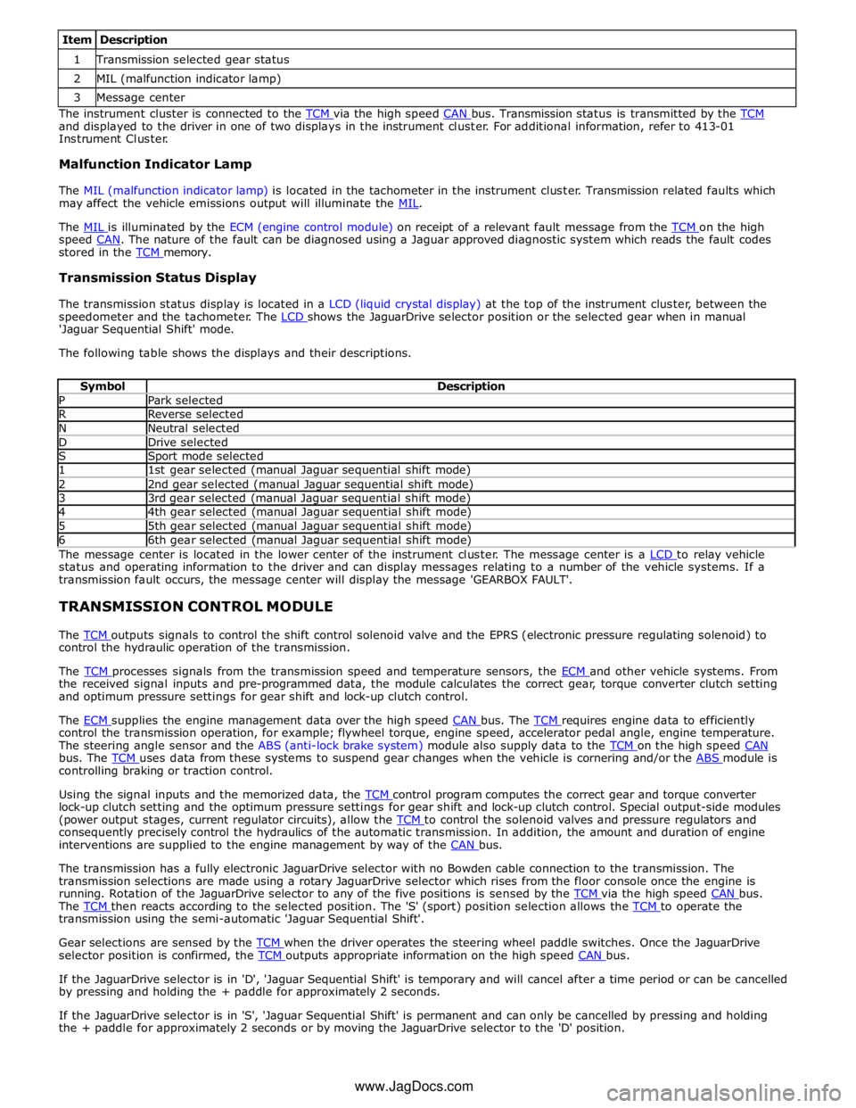
1 Transmission selected gear status 2 MIL (malfunction indicator lamp) 3 Message center The instrument cluster is connected to the TCM via the high speed CAN bus. Transmission status is transmitted by the TCM and displayed to the driver in one of two displays in the instrument cluster. For additional information, refer to 413-01
Instrument Cluster.
Malfunction Indicator Lamp
The MIL (malfunction indicator lamp) is located in the tachometer in the instrument cluster. Transmission related faults which
may affect the vehicle emissions output will illuminate the MIL.
The MIL is illuminated by the ECM (engine control module) on receipt of a relevant fault message from the TCM on the high speed CAN. The nature of the fault can be diagnosed using a Jaguar approved diagnostic system which reads the fault codes stored in the TCM memory.
Transmission Status Display
The transmission status display is located in a LCD (liquid crystal display) at the top of the instrument cluster, between the
speedometer and the tachometer. The LCD shows the JaguarDrive selector position or the selected gear when in manual 'Jaguar Sequential Shift' mode.
The following table shows the displays and their descriptions.
Symbol Description P Park selected R Reverse selected N Neutral selected D Drive selected S Sport mode selected 1 1st gear selected (manual Jaguar sequential shift mode) 2 2nd gear selected (manual Jaguar sequential shift mode) 3 3rd gear selected (manual Jaguar sequential shift mode) 4 4th gear selected (manual Jaguar sequential shift mode) 5 5th gear selected (manual Jaguar sequential shift mode) 6 6th gear selected (manual Jaguar sequential shift mode) The message center is located in the lower center of the instrument cluster. The message center is a LCD to relay vehicle status and operating information to the driver and can display messages relating to a number of the vehicle systems. If a
transmission fault occurs, the message center will display the message 'GEARBOX FAULT'.
TRANSMISSION CONTROL MODULE
The TCM outputs signals to control the shift control solenoid valve and the EPRS (electronic pressure regulating solenoid) to control the hydraulic operation of the transmission.
The TCM processes signals from the transmission speed and temperature sensors, the ECM and other vehicle systems. From the received signal inputs and pre-programmed data, the module calculates the correct gear, torque converter clutch setting
and optimum pressure settings for gear shift and lock-up clutch control.
The ECM supplies the engine management data over the high speed CAN bus. The TCM requires engine data to efficiently control the transmission operation, for example; flywheel torque, engine speed, accelerator pedal angle, engine temperature.
The steering angle sensor and the ABS (anti-lock brake system) module also supply data to the TCM on the high speed CAN bus. The TCM uses data from these systems to suspend gear changes when the vehicle is cornering and/or the ABS module is controlling braking or traction control.
Using the signal inputs and the memorized data, the TCM control program computes the correct gear and torque converter lock-up clutch setting and the optimum pressure settings for gear shift and lock-up clutch control. Special output-side modules
(power output stages, current regulator circuits), allow the TCM to control the solenoid valves and pressure regulators and consequently precisely control the hydraulics of the automatic transmission. In addition, the amount and duration of engine
interventions are supplied to the engine management by way of the CAN bus.
The transmission has a fully electronic JaguarDrive selector with no Bowden cable connection to the transmission. The
transmission selections are made using a rotary JaguarDrive selector which rises from the floor console once the engine is
running. Rotation of the JaguarDrive selector to any of the five positions is sensed by the TCM via the high speed CAN bus. The TCM then reacts according to the selected position. The 'S' (sport) position selection allows the TCM to operate the transmission using the semi-automatic 'Jaguar Sequential Shift'.
Gear selections are sensed by the TCM when the driver operates the steering wheel paddle switches. Once the JaguarDrive selector position is confirmed, the TCM outputs appropriate information on the high speed CAN bus.
If the JaguarDrive selector is in 'D', 'Jaguar Sequential Shift' is temporary and will cancel after a time period or can be cancelled
by pressing and holding the + paddle for approximately 2 seconds.
If the JaguarDrive selector is in 'S', 'Jaguar Sequential Shift' is permanent and can only be cancelled by pressing and holding
the + paddle for approximately 2 seconds or by moving the JaguarDrive selector to the 'D' position.
www.JagDocs.com
Page 1423 of 3039
The TCM can be reprogrammed using a Jaguar approved diagnostic system using a flash code. The TCM processor has a 440 kb internal flash memory. Of this capacity, approximately 370 kb are used by the basic transmission program. The remainder,
approximately 70 kb is used to store vehicle-specific application data.
Engine Stall
If the vehicle stalls it will coast down in gear, with the transmission providing drive to the engine. A restart can be attempted
at this point and the engine may start and the driver can continue.
If the coast down speed reduces such that the speed of the engine is less than 600 rev/min, the transmission will go to
neutral, D illumination will flash in the instrument cluster. The driver needs to select neutral or park and then press the brake
pedal to restart the engine.
If the start/stop button is pressed when driving, the message ENGINE STOP BUTTON PRESSED is displayed in the message
center but there will be no change to the ignition state. If the driver requires to switch off the engine, the start/stop button
must be pressed for a second time. The engine will be stopped and will be back driven by the transmission as the vehicle
coasts down. When the engine speed is less than 600 rev/min the transmission engages neutral (flashing D illumination in the
instrument cluster). When vehicle speed is less than 2 km/h (1.2 mph) Park is engaged. The JaguarDrive selector automatically
rotates back to its lowered P position and the vehicle ignition is switched off.
The park engagement is prevented in a stall case as the ignition power is on and D was the last selected gear. The park
engagement speed at ignition off is from the least value of the wheel speeds (CAN signal) and transmission output speed (internal signal).
TRANSMISSION Component Description
The transmission comprises the main casing which houses all of the transmission components. The main casing also
incorporates an integral bell housing.
A fluid pan is attached to the lower face of the main casing and is secured with bolts. The fluid pan is sealed to the main
casing with a gasket. Removal of the fluid pan allows access to the Mechatronic valve block. The fluid pan has a magnet
located around the drain plug which collects any metallic particles present in the transmission fluid.
A fluid filter is located inside the fluid pan. If the transmission fluid becomes contaminated or after any service work, the fluid
pan with integral filter must be replaced.
The integral bell housing provides protection for the torque converter assembly and also provides the attachment for the
gearbox to the engine cylinder block. The torque converter is a non-serviceable assembly which also contains the lock-up clutch
mechanism. The torque converter drives a crescent type pump via drive tangs. The fluid pump is located in the main casing,
behind the torque converter.
The main casing contains the following major components:
Input shaft
Output shaft
Mechatronic valve block which contains the solenoids, speed sensors and the TCM Three rotating multiplate drive clutches
Two fixed multiplate brake clutches
A single planetary gear train and a double planetary gear train.
Page 1430 of 3039

1 Securing ring 2 Shaft oil seal 3 O-ring seal 4 Pump housing 5 Ring gear 6 Crescent spacer 7 Roller bearing 8 Impeller 9 Centering pin 10 Spring washer 11 Outlet port (high pressure) 12 Inlet port (low pressure) The pump comprises a housing, a crescent spacer, an impeller and a ring gear. The housing has inlet and outlet ports to direct
flow and is located in the intermediate plate by a centering pin. The pump action is achieved by the impeller, ring gear and
crescent spacer.
The crescent spacer is fixed in its position by a pin and is located between the ring gear and the impeller. The impeller is
driven by drive from the torque converter hub which is located on a needle roller bearing in the pump housing. The impeller
teeth mesh with those of the ring gear. When the impeller is rotated, the motion is transferred to the ring gear which rotates
in the same direction.
The rotational motion of the ring gear and the impeller collects fluid from the intake port in the spaces between the teeth.
When the teeth reach the crescent spacer, the oil is trapped in the spaces between the teeth and is carried with the rotation
of the gears. The spacer tapers near the outlet port. This reduces the space between the gear teeth causing a build up of fluid
pressure as the oil reaches the outlet port. When the teeth pass the end of the spacer the pressurized fluid is released into
the outlet port.
The fluid emerging from the outlet port is passed through the fluid pressure control valve. At high operating speeds the
pressure control valve maintains the output pressure to the gearbox at a predetermined maximum level. Excess fluid is
relieved from the pressure control valve and is directed, via the main pressure valve in the valve block, back to the pump inlet
port. This provides a pressurized feed to the pump inlet which prevents cavitation and reduces pump noise.
Page 1440 of 3039

DTC Description Possible Cause Action P0721-64
Output Shaft Speed Sensor
Circuit Range/Performance -
signal plausibility failure
Signal plausibility failure Clear DTC and test. If code re-detects suspect the
Transmission control module. Install a new
Transmission control module as required, refer to the
new module/component installation note at the top of
the DTC Index P0731-07
Incorrect Gear Ratio-
Mechanical Failures
Gear Ratio Monitoring.
Mechanical Failures Check and correct oil level. Clear DTC. If code
re-detects suspect Transmission (gearbox) internal
fault. Install a new Transmission as required, refer to
the new module/component installation note at the top of the DTC Index P0732-07
Incorrect Gear Ratio-
Mechanical Failures
Gear Ratio Monitoring.
Mechanical Failures Check and correct oil level. Clear DTC. If code
re-detects suspect Transmission (gearbox) internal
fault. Install a new Transmission as required, refer to
the new module/component installation note at the top of the DTC Index P0733-07
Incorrect Gear Ratio-
Mechanical Failures
Gear Ratio Monitoring.
Mechanical Failures Check and correct oil level. Clear DTC. If code
re-detects suspect Transmission (gearbox) internal
fault. Install a new Transmission as required, refer to
the new module/component installation note at the top of the DTC Index P0734-07
Incorrect Gear Ratio-
Mechanical Failures
Gear Ratio Monitoring.
Mechanical Failures Check and correct oil level. Clear DTC. If code
re-detects suspect Transmission (gearbox) internal
fault. Install a new Transmission as required, refer to
the new module/component installation note at the top of the DTC Index P0735-07
Incorrect Gear Ratio-
Mechanical Failures
Gear Ratio Monitoring.
Mechanical Failures Check and correct oil level. Clear DTC. If code
re-detects suspect Transmission (gearbox) internal
fault. Install a new Transmission as required, refer to
the new module/component installation note at the top of the DTC Index P0736-07
Incorrect Gear Ratio-
Mechanical Failures
Gear Ratio Monitoring.
Mechanical Failures Check and correct oil level. Clear DTC. If code
re-detects suspect Transmission (gearbox) internal
fault. Install a new Transmission as required, refer to
the new module/component installation note at the top of the DTC Index P0740-13 Torque Converter Clutch
Solenoid Circuit / Open -
Circuit Open
Pressure control solenoid
2 Circuit Open Circuit Clear DTC and test. If code re-detects suspect the
Transmission control module. Install a new
Transmission control module as required, refer to the
new module/component installation note at the top of
the DTC Index P0741-07 Torque Converter Clutch
Solenoid Circuit
Performance/Stuck Off -
Mechanical Failures
Too high slip at torque
converter clutch.
Mechanical Failures Suspect torque converter lockup clutch. Install a new
torque converter, refer to the new module/component
installation note at the top of the DTC Index. If
transmission fluid is in very poor condition and dirty,
install a new transmission, refer to the new
module/component installation note at the top of the
DTC Index P0745-04 Pressure Control Solenoid A
- System Internal Failures
System Internal Failures Suspect the Transmission control module. Install a
new Transmission control module as required, refer to
the new module/component installation note at the top of the DTC Index P0745-48 Pressure Control Solenoid A
- Supervision Software
Failure
Supervision Software
Failure Suspect the Transmission control module. Install a
new Transmission control module as required, refer to
the new module/component installation note at the top of the DTC Index P0758-12
Shift Solenoid B Electrical -
Circuit Short to Battery
Circuit Short to Power Suspect the Transmission control module. Install a
new Transmission control module as required, refer to
the new module/component installation note at the top of the DTC Index P0758-13
Shift Solenoid B Electrical -
Circuit Open
Solenoid valve 1 or
Pressure control Solenoid
G Circuit Open Circuit Suspect the Transmission control module. Install a
new Transmission control module as required, refer to
the new module/component installation note at the
top of the DTC Index P0771-71
Shift Solenoid E
Performance/Stuck Off -
actuator stuck
Actuator stuck Suspect the Transmission control module. Install a
new Transmission control module as required, refer to
the new module/component installation note at the top of the DTC Index P0775-04 Pressure Control Solenoid B
- System Internal Failures
System Internal Failures Suspect the Transmission control module. Install a
new Transmission control module as required, refer to
the new module/component installation note at the top of the DTC Index P0775-48 Pressure Control Solenoid B
- Supervision Software
Failure
Supervision Software
Failure Suspect the Transmission control module. Install a
new Transmission control module as required, refer to
the new module/component installation note at the top of the DTC Index
Page 1441 of 3039

DTC Description Possible Cause Action P0781-07
1-2 Shift - Mechanical
Failures
Gear Ratio Monitoring.
Mechanical Failures Check and correct oil level. Clear DTC. If code
re-detects suspect Transmission (Gearbox) internal
fault. Install a new Transmission as required, refer to
the new module/component installation note at the top of the DTC Index P0781-77
2-1 Shift - commanded
position not reachable
Gear Ratio Monitoring.
Mechanical Failures Check and correct oil level. Clear DTC. If code
re-detects suspect Transmission (Gearbox) internal
fault. Install a new Transmission as required, refer to
the new module/component installation note at the top of the DTC Index P0782-07
2-3 Shift - commanded
position not reachable
Gear Ratio Monitoring.
Mechanical Failures Check and correct oil level. Clear DTC. If code
re-detects suspect Transmission (Gearbox) internal
fault. Install a new Transmission as required, refer to
the new module/component installation note at the top of the DTC Index P0782-77
3-2 Shift - commanded
position not reachable
Gear Ratio Monitoring.
Mechanical Failures Check and correct oil level. Clear DTC. If code
re-detects suspect Transmission (Gearbox) internal
fault. Install a new Transmission as required, refer to
the new module/component installation note at the top of the DTC Index P0783-07
3-4 Shift - Mechanical
Failures
Gear Ratio Monitoring.
Mechanical Failures Check and correct oil level. Clear DTC. If code
re-detects suspect Transmission (Gearbox) internal
fault. Install a new Transmission as required, refer to
the new module/component installation note at the top of the DTC Index P0783-77
3-4 Shift - commanded
position not reachable
Gear Ratio Monitoring.
Mechanical Failures Check and correct oil level. Clear DTC. If code
re-detects suspect Transmission (Gearbox) internal
fault. Install a new Transmission as required, refer to
the new module/component installation note at the top of the DTC Index P0784-07
4-5 Shift - Mechanical
Failures
Gear Ratio Monitoring.
Mechanical Failures Check and correct oil level. Clear DTC. If code
re-detects suspect Transmission (Gearbox) internal
fault. Install a new Transmission as required, refer to
the new module/component installation note at the top of the DTC Index P0784-77
4-5 Shift - commanded
position not reachable
Gear Ratio Monitoring.
Mechanical Failures Check and correct oil level. Clear DTC. If code
re-detects suspect Transmission (Gearbox) internal
fault. Install a new Transmission as required, refer to
the new module/component installation note at the top of the DTC Index P0798-1A
Pressure Control Solenoid C
Electrical - Circuit Resistance
Below Threshold
Pressure control solenoid
C Circuit resistance
below threshold Suspect the Transmission control module. Install a
new Transmission control module as required, refer to
the new module/component installation note at the
top of the DTC Index P0798-1E
Pressure Control Solenoid C
Electrical - Circuit Short to
Ground
Pressure control solenoid
C electrical circuit short
to ground Suspect the Transmission control module. Install a
new Transmission control module as required, refer to
the new module/component installation note at the
top of the DTC Index P0798-21
Pressure Control Solenoid C
Electrical - signal amplitude
< minimum
Pressure Control Solenoid
C Electrical signal
amplitude < minimum Suspect the Transmission control module. Install a
new Transmission control module as required, refer to
the new module/component installation note at the
top of the DTC Index P0814-62 Transmission Range Display
Circuit - signal compare
failure
Transmission Range
Display Circuit signal
compare failure Suspect the Transmission control module. Install a
new Transmission control module as required, refer to
the new module/component installation note at the
top of the DTC Index P0826-08
Up and Down Switch circuit -
Bus Signal Message Failures
Invalid CAN signal from
BCM/Instrument cluster
Stuck switch
CAN bus circuit fault Check Central junction box and Instrument cluster for
stored DTCs. Check gear change switches for correct
operation. Refer to circuit diagrams and check CAN bus
for a circuit fault P0826-81
Up and Down Switch Circuit -
invalid serial data received
Invalid Can signal from
BCM / Instrument cluster
Stuck switch
CAN Bus Circuit fault Check Central junction box and Instrument cluster for
stored DTCs. Check Gear Change Switches for correct
operation. Refer to Circuit diagrams and check CAN
Bus for Circuit fault P0826-88
Up and Down Switch Circuit -
Bus off
SWM to BCM /
Instrument cluster LIN
Bus failure Check Central junction box and Steering Wheel Ice
Switches for stored DTCs. Refer to Circuit diagrams
and check LIN Bus for Circuit fault