JAGUAR XJ6 1994 2.G Workshop Manual
Manufacturer: JAGUAR, Model Year: 1994, Model line: XJ6, Model: JAGUAR XJ6 1994 2.GPages: 521, PDF Size: 17.35 MB
Page 211 of 521

1. SERVICE TOOLS & EQUIPMENT
Illustration
Not illustrated
Jaguar Number
JDID
JD 60
JDIOO
JD115
JD133
JD135
JD143
JD143-1
50143-2
JD143-3
Description
Hub Remover Rear Suspension
Nishbone Upper Bush Remover
1 Replacer
Remover Steering Arm and Swivel
Hub Ball Pins
Spring Compressor Front Suspension
Camber Tie Down Link (Front)
RemoverIRenewer Front Damper
Lower Bush
Remover
1 Renewer Suspension
Bushes (Main
Tool)
Adaptor Ring Front Sub Frame Rear
Bushes
Anvil adapter
Adaptor Remover
1 Renewer
Suspension Bushes
Issue 1 August 1994 ii X300 VSM
Page 212 of 521

Suspension Systems
Not illustrated
1. SERVICE TOOLS & EQUIPMENT (continued)
JD199
0
Fixing
To be issued
Tightening Torque
(Nm)
JD199-1 Not i II ustrated
Description US98
LM Multi - purpose grease
Molib Alloy
PI907 No1
Molykote 11 1
Lower damper bolt
Wishbone to crossmember fulcrum shaft
Stabilizer mounting bushes
& rear damper top
guide bush
Caliper to carrier bolts
/ guide pins
Description
Notes
Adaptor Remover / Renewer
Suspension Bushes (Bottom Front
Wishbone Inner)
____~ ~ Spring
Compressor Rear Suspension
Damper Retaining Tie Rear
Suspension
Adaptor
Replacer Rear Hub Pivot
Bearing Cup
Driver Handle
Adaptor Remover
Main Shaft Pilot
Bearing Outer Track
Impulse Extractor (slide Hammer)
UNF. Basic Tool
Notes
Issue 1 August 1994 X300 VSM iii
Page 213 of 521
Suspension Systems
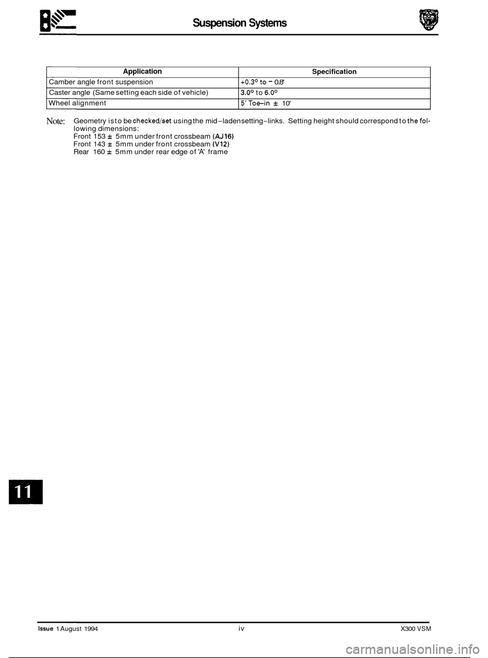
Application
Camber angle front suspension
Caster angle (Same setting each side of vehicle)
Wheel alignment
Specification
+0.3' to - 0.8'
3.0' to 6.0'
5'Toe-in f 10'
Note: Geometry is to be checked/set using the mid-laden setting-links. Setting height should correspond to thefol- lowing dimensions:
Front 153 f 5mm under front crossbeam (AJ16) Front 143 f 5mm under front crossbeam (V12) Rear 160 f 5mm under rear edge of 'A' frame
Issue 1 August 1994 iv X300 VSM
Page 214 of 521

Suspension Systems
11.1 INTRODUCTION
This section describes the front and rear suspension systems, and also covers diagnostic procedures.
Fig. 1 Front Suspension Layout
11.2 FRONT SUSPENSION, DESCRIPTION
Theupperrearwishbone(1 Fig.l)andthe upperfrontwishbone(2 Fig.1)arepivotedon the upperfulcrum bolt (3Fig.l), passing through the front cross beam assembly. They are also fitted via an upper ball joint assembly (4 Fig.1) to a verti- cal linkaccommodating the stub axle (5 Fig.l), whereas the vertical linkisfittedvia a lower ball joint assembly (6 Fig.1) to the lower wishbone assembly.
The lower wishbone assembly comprises
a lower rear wishbone (7 Fig.l), lower front wishbone (8 Fig.l), damper (9 Fig.1) (incorporating damper bush 10 Fig.1) and spring pan (1 1 Fig.1) supporting the road spring (12 Fig.1). The lower
wishbone assembly is pivoted on the bushed lower fulcrum shaft (13 Fig.1) which also passes through thecross beam
assembly.
Both independent front suspension assemblies are linked by a stabilizer bar (14 Fig.1) which is secured to the cross
member using a fixing arrangement of mounting rubbers (15 Fig.1, clamps (16 Fig.l), nuts bolts, washers (17 Fig.1) and two link arm assemblies (18 Fig.1). Each link arm assembly is fitted to one end of the stabilizer bar and to one end
of the lower front wishbone using a fixing arrangement of bolts washers and self locking nuts.
All suspension loads, except the damper, are fed into a pressed steel crossbeam which is isolated from the body by
rubber bushes. This mounting method allows the necessary amount of compliance.
The degree
of caster is adjustable via shims positioned on either side of the upper ball joint assembly but camber is facton/ set and is not adjustable. The vertical link and the steering arm form a single forging. Cast iron hubs rotate
on twin tapered roller bearings.
X300 VSM 1 Issue 1 August 1994
Page 215 of 521
Suspension Systems
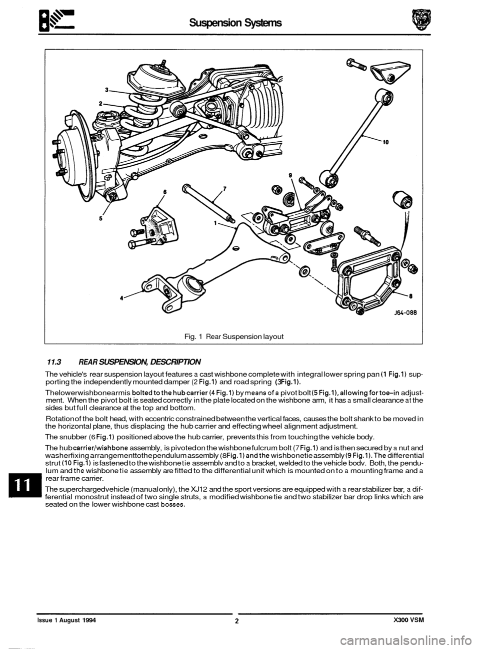
Fig. 1 Rear Suspension layout
11.3 REAR SUSPENSION, DESCRIPTION
The vehicle's rear suspension layout features a cast wishbone complete with integral lower spring pan (1 Fig.1) sup- porting the independently mounted damper (2 Fig.1) and road spring (3 Fig.1).
Thelowerwishbonearmis boltedtothehubcarrier(4 Fig.1) by meansofa pivot bolt (5Fig.l),allowingfortoe-in adjust- ment. When the pivot bolt is seated correctly in the plate located on the wishbone arm, it has a small clearance at the
sides but full clearance at the top and bottom.
Rotation of the bolt head, with eccentric constrained between the vertical faces, causes the bolt shank to be moved in
the horizontal plane, thus displacing the hub carrier and effecting wheel alignment adjustment.
The snubber
(6 Fig.1) positioned above the hub carrier, prevents this from touching the vehicle body.
The hub
carrier/wishbone assembly, is pivoted on the wishbone fulcrum bolt (7 Fig.1) and is then secured by a nut and
washerfixing arrangementtothe pendulum assembly (8 Fig.1) andthe wishbonetie assembly (9 Fig.l).The differential
strut (10 Fia.1) is fastened to the wishbone tie assemblv and to a bracket, welded to the vehicle bodv. Both, the pendu- lum and the wishbone tie assembly are fitted to the differential unit which is mounted on to a mounting frame and a rear frame carrier.
The supercharged vehicle (manual only), the XJ12 and the sport versions are equipped with
a rear stabilizer bar, a dif- ferential monostrut instead of two single struts, a modified wishbone tie and two stabilizer bar drop links which are
seated on the lower wishbone cast bosses.
0
0
e
Issue 1 August 1994 X300 VSM
Page 216 of 521
may include:
0
0
Loose or worn wheel bearings.
Loose or worn suspensions or steering components.
0 Worn or damaged drive shaft slip yoke joint.
0 Front disc rotor runout.
o Loose engine or transmission supports.
0 Driveline alignment.
0 Engine driven accessories.
Suspension Systems
11.4 DIAGNOSIS AND TESTING
' 11.4.1 Tire Wear
Tires should be inspected as abnormal or excessive wear may becaused by incorrect wheel alignment, wheelbire im- balance, or incorrect tire pressure.
1 1.4.2 vibration and Roughness
Vibration, roughness, and shimmy conditions may be caused by excessive tire or wheel runout, worn or cupped tires,
or wheel and tire unbalance.
Most of these conditions are due to irregularities in the road surface, hence driving the vehicle on different types of
road surface will often indicate the cause of the condition.
Do not automatically suspect the tires when attempting to diagnose a vibration concern as other sources of vibration
Before investigating any other vibration concerns,
a roaG &est and a customer inter\,.dw (if possible) should be carried
out. This can provide much of the information needed to find the source of vibration.
Drive the vehicle on a road that is preferably smooth and free of undulation and
if vibration is apparent note, the speed at which thevibration occurs, whattype of vibration occurs in each speed range (mechanical or audible), howthevibra- tion is affected by changes in vehicle speed , engine speed and engine torque, and the type of vibration sensitivity
(torque sensitive, vehicle speed sensitive, or speed sensitive).
Some of the condition terms used when describing sources of vibration are explained as follows:
0 Torque Sensitive
This condition can be improved or worsened by accelerating, decelerating, coasting, maintaining
a steady
vehicle speed and application of engine torque.
0 Vehicle Speed Sensitive
This means that the vibration always occurs at the same vehicle speed and is not affected by engine torque,
engine rpm, or transmission gear selection.
B
0 Engine Speed Sensitive
This means that the vibration occurs
at varying vehicle speeds when a different transmission gear is selected.
It can sometimes be isolated by increasing or decreasing engine speed with the transmission in 'NEUTRAL', or
by stall testing with the engine in gear. If the condition is enginesensitive, the condition is not related to tires.
If the road tests indicates that the vibration is related to the tires or wheels,use a 'lire Wear Diagnosis Chart' to
investigate the cause of concern. Should the road test indicate that there is tire whine, but noshake or vibration,
the noise originates from the contact between the tire and the road surface.
X300 VSM 3 Issue 1 August 1994
Page 217 of 521
Suspension Systems
11.4.3 Front End Inspection
Do not check and adjust front wheel alignment without carrying out the following inspection for front end damage and
wear:
. Check for specified air pressure in all four tires.
Raise front of vehicle off the floor; grasping upper and lower surface of the tire, shake each front wheel to check for
. Check front suspension lower arm ball joint and mounts for looseness, wear and damage.
Check steering gear mountings and all steering linkages for looseness.
. Renew parts if necessary.
. Grasp upper and lower surface of tire and shake each wheel to check wheel bearing end play.
. Check the action of the front dampers and the condition of their attachments, as sticking or binding front dampers
worn
bearings.
Check brake caliper mountings.
may not allow the vehicle to settle in to a normal level position, possibly affecting the front-wheel alignment.
m: Front wheel bearings are adjustable (0.001 to 0.003 in. endfloat).
11.4.4
. Check the wheel bearings.
. Inspect the front suspension upper joint and renew front suspension lower wishbone if needed.
Raise vehicle and position floor jacks beneath the front suspension lower wishbone.
Grasp the lower edge of the tire and move the wheel in and out.
While moving the wheel, observe the upper and lower wishbone.
. Movement between the vertical links and the wishbones indicates abnormal ball joint wear.
. Renew ball joints.
. Check the front wheel bearings.
. Check for excessive play and wear.
Upper / Lower Ball Joint Inspection
11.4.5 Damper Inspection
m: The gas-pressurized hydraulic front dampers are not serviceable, adjustable or refillable.
Verify that all attachments of the suspension components and the front dampers are tight. Renew any front damper
. Check front dampers for external damage.
. Check for oil leakage and vehicle sag.
that
has a damaged integral lower mounting bushing.
0 Oil Leak
Leakage is the condition in which the entire damper body is covered with oil and from where
it will drip on to
the pavement. Due to correct damper lubrication a light film of oil (weepage) can usually be seen on the upper
portion of the damper.
Should there be any leakage, ensure that the fluid does not originate from sources other than the front damper.
Renew worn or damaged dampers.
0 Vehicle Sag
Renewing front dampers will not correct the problem of vehicle sag, as basically this is controlled by the spring
units.
issue 1 August 1994 4 X300 VSM
Page 218 of 521
Suspension Systems
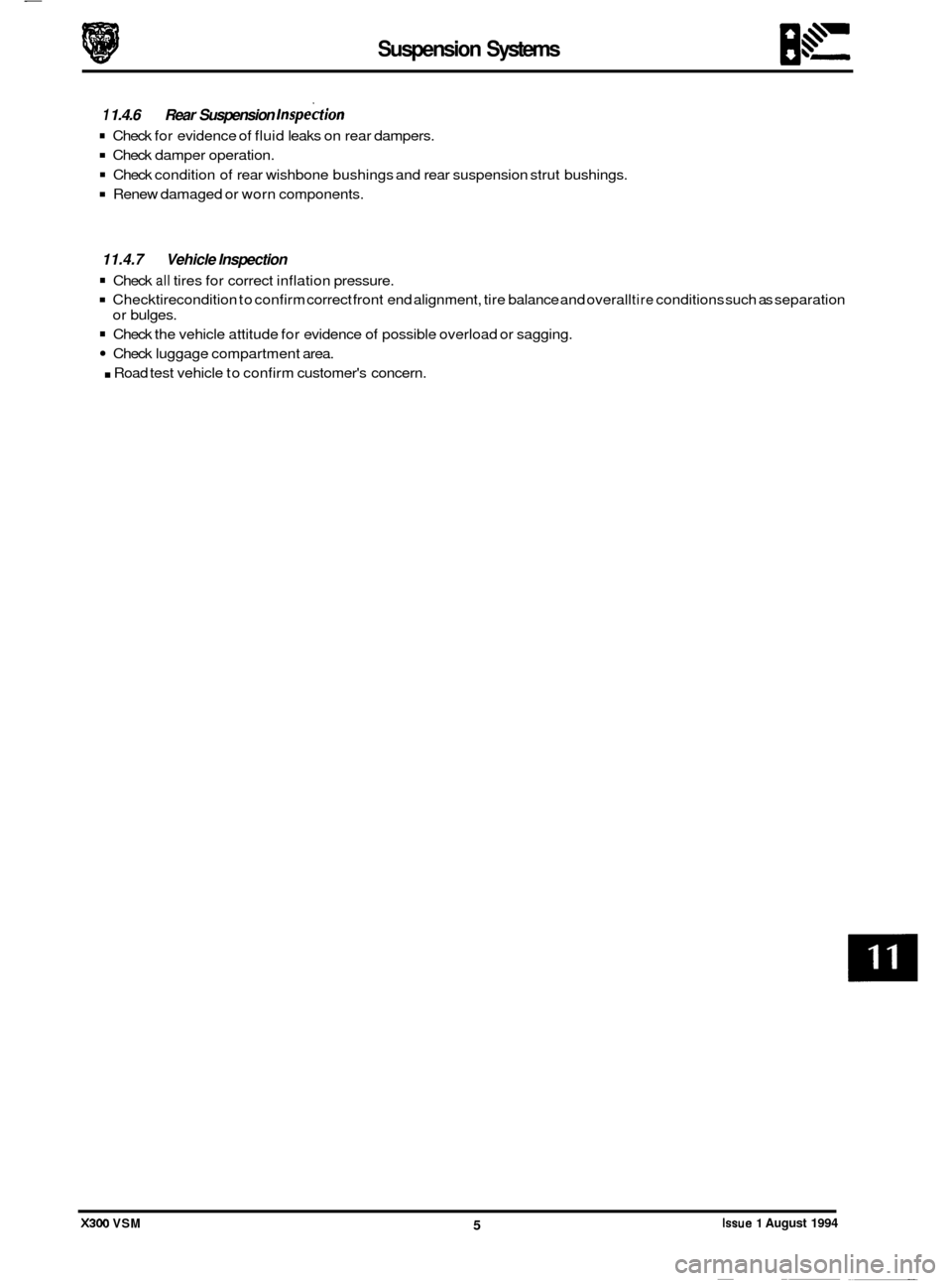
1 1.4.6 Rear Suspension lnspe&on
Check damper operation.
Check condition of rear wishbone bushings and rear suspension strut bushings.
Renew damaged or worn components.
0 Check for evidence of fluid leaks on rear dampers.
11.4.7 Vehicle Inspection
Check all tires for correct inflation pressure.
Checktire condition to confirm correct front end alignment, tire balance and overall tire conditions such as separation
Check the vehicle attitude for evidence of possible overload or sagging.
Check luggage compartment area.
. Road test vehicle to confirm customer's concern.
or
bulges.
X300 VSM 5 Issue 1 August 1994 ~ ~~
Page 219 of 521
Suspension Systems
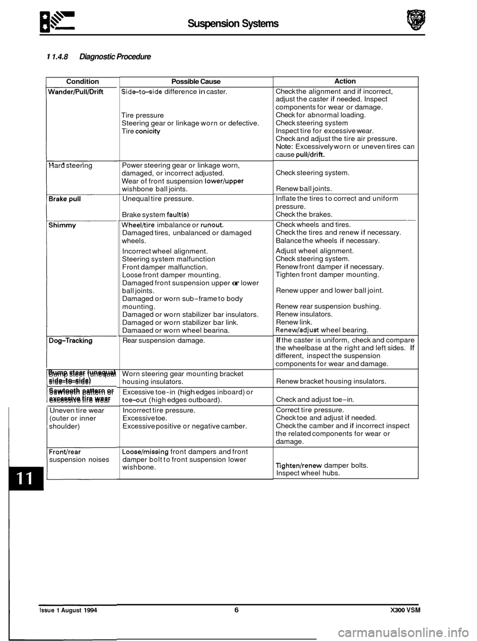
1 1.4.8 Diagnostic Procedure
Condition
Hard steering
Shimmy
I----
Bump steer (unequal
side-to-side)
Sawtooth pattern or
t excessive tire wear
Uneven tire wear
(outer or inner
shoulder)
Fronvrear
suspension noises
Possible Cause
Side-to-side difference in caster.
Tire pressure Steering gear or linkage worn or defective.
Tire
conicity
Power steering gear or linkage worn,
damaged, or incorrect adjusted.
Wear of front suspension
lower/upper
wishbone ball joints.
Unequal tire pressure.
Brake system
fault(s)
Wheel/tire imbalance or runout.
Damaged tires, unbalanced or damaged
wheels.
Incorrect wheel alignment.
Steering system malfunction
Front damper malfunction.
Loose front damper mounting.
Damaged front suspension upper
or lower
ball joints.
Damaged or worn sub
-frame to body
mounting. Damaged or worn stabilizer bar insulators.
Damaged or worn stabilizer bar link.
Damaaed or worn wheel bearina.
Rear suspension damage.
Worn steering gear mounting bracket
housing insulators.
Excessive toe
-in (high edges inboard) or
toe-out (high edges outboard).
Incorrect tire pressure.
Excessive toe.
Excessive positive or negative camber.
Loose/missing front dampers and front
damper bolt to front suspension lower
wish bone.
Action
Check the alignment and if incorrect,
adjust the caster
if needed. Inspect
components for wear or damage.
Check for abnormal loading.
Check steering system
Inspect tire for excessive wear.
Check and adjust the tire air pressure.
Note: Excessively worn or uneven tires can
cause
pull/drift.
Check steering system.
Renew ball joints.
Inflate the tires to correct and uniform
pressure.
Check the brakes.
Check wheels and tires.
Check the tires and renew
if necessary.
Balance the wheels
if necessary.
Adjust wheel alignment.
Check steering system.
Renew front damper
if necessary.
Tighten front damper mounting.
-
Renew upper and lower ball joint.
Renew rear suspension bushing.
Renew insulators.
Renew link.
Renew/adjust wheel bearing.
If the caster is uniform, check and compare
the wheelbase at the right and left sides.
If
different, inspect the suspension
components for wear and damage.
Renew bracket housing insulators.
Check and adjust toe
-in.
Correct tire pressure.
Check toe and adjust
if needed.
Check the camber and
if incorrect inspect
the related components for wear or
damage.
Tighten/renew damper bolts.
Inspect wheel hubs.
0
0
0
lssue 1 August 1994 6 X300 VSM
Page 220 of 521
Suspension Systems I.\" b-
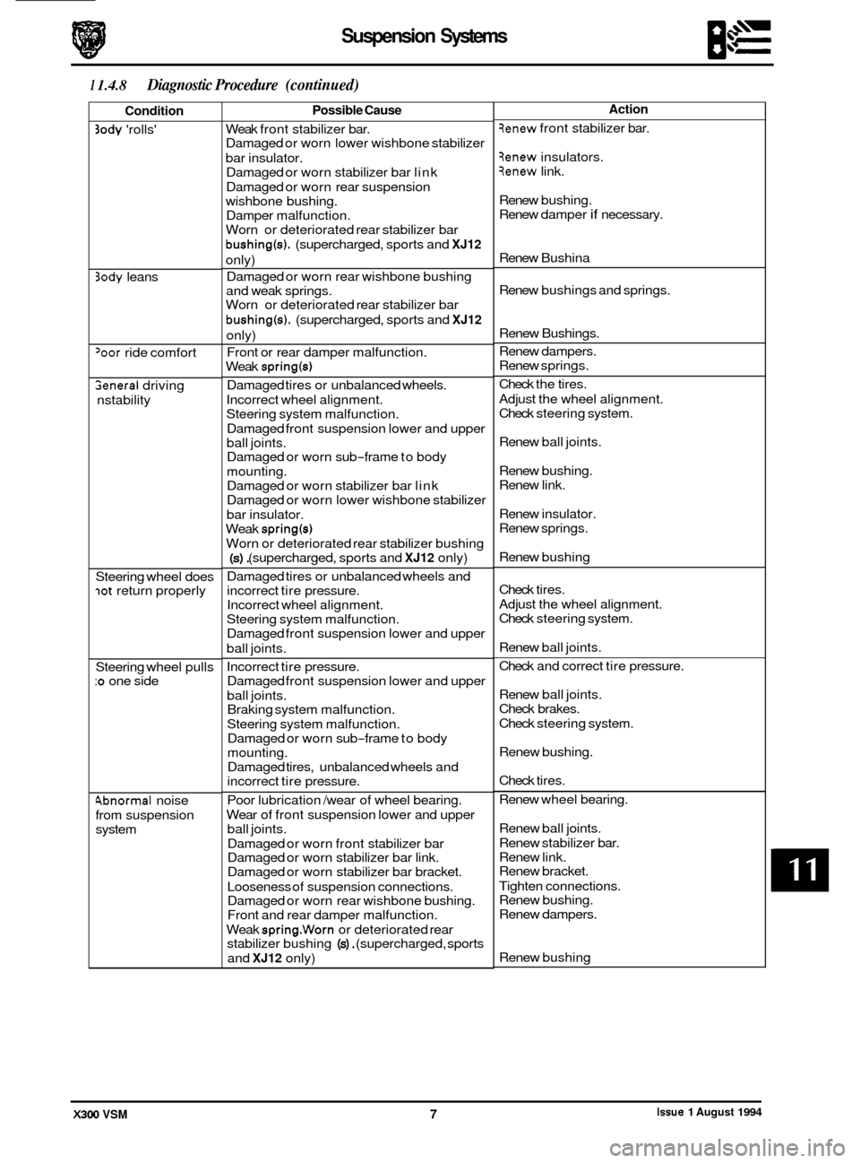
1 1.4.8 Diagnostic Procedure (continued)
Condition
30dy 'rolls'
3ody leans
'oor ride comfort
Seneral driving
nstability
Steering wheel does
lot return properly
Steering wheel pulls
:o one side
4bnormal noise
from suspension
system
Possible Cause
Weak front stabilizer bar.
Damaged or worn lower wishbone stabilizer
bar insulator. Damaged or worn stabilizer bar link
Damaged or worn rear suspension
wishbone bushing.
Damper malfunction.
Worn or deteriorated rear stabilizer bar
bushing(s). (supercharged, sports and XJ12
only)
Damaged or worn rear wishbone bushing
and weak springs.
Worn or deteriorated rear stabilizer bar
bushing(s). (supercharged, sports and XJ12
only)
Front or rear damper malfunction.
Weak
spring(s1
Damaged tires or unbalanced wheels.
Incorrect wheel alignment.
Steering system malfunction.
Damaged front suspension lower and upper
ball joints.
Damaged or worn sub
-frame to body
mounting.
Damaged or worn stabilizer bar link
Damaged or worn lower wishbone stabilizer
bar insulator.
Weak
spring(s)
Worn or deteriorated rear stabilizer bushing
(s). (supercharged, sports and XJ12 only)
Damaged tires or unbalanced wheels and
incorrect tire pressure.
Incorrect wheel alignment.
Steering system malfunction.
Damaged front suspension lower and upper
ball joints.
Incorrect tire pressure.
Damaged front suspension lower and upper
ball joints. Braking system malfunction.
Steering system malfunction.
Damaged or worn sub
-frame to body
mounting.
Damaged tires, unbalanced wheels and
incorrect tire pressure.
Poor lubrication /wear of wheel bearing.
Wear of front suspension lower and upper
ball joints.
Damaged or worn front stabilizer bar
Damaged or worn stabilizer bar link.
Damaged or worn stabilizer bar bracket.
Looseness of suspension connections.
Damaged or worn rear wishbone bushing.
Front and rear damper malfunction.
Weak
spring.Worn or deteriorated rear
stabilizer bushing
(s). (supercharged, sports
and
XJ12 only)
Action
3enew front stabilizer bar.
3enew insulators.
3enew link.
Renew bushing.
Renew damper
if necessary.
Renew Bushina
Renew bushings and springs.
Renew Bushings.
Renew dampers.
Renew springs.
Check the tires.
Adjust the wheel alignment.
Check steering system.
Renew ball joints.
Renew bushing.
Renew link.
Renew insulator.
Renew springs.
Renew bushing
Check tires.
Adjust the wheel alignment.
Check steering system.
Renew ball joints.
Check and correct tire pressure.
Renew ball joints.
Check brakes.
Check steering system.
Renew bushing.
Check tires.
Renew wheel bearing.
Renew ball joints.
Renew stabilizer bar.
Renew link.
Renew bracket.
Tighten connections.
Renew bushing.
Renew dampers.
Renew bushing
Issue 1 August 1994 X300 VSM 7