JEEP CHEROKEE 1995 Service Repair Manual
Manufacturer: JEEP, Model Year: 1995, Model line: CHEROKEE, Model: JEEP CHEROKEE 1995Pages: 2198, PDF Size: 82.83 MB
Page 1811 of 2198
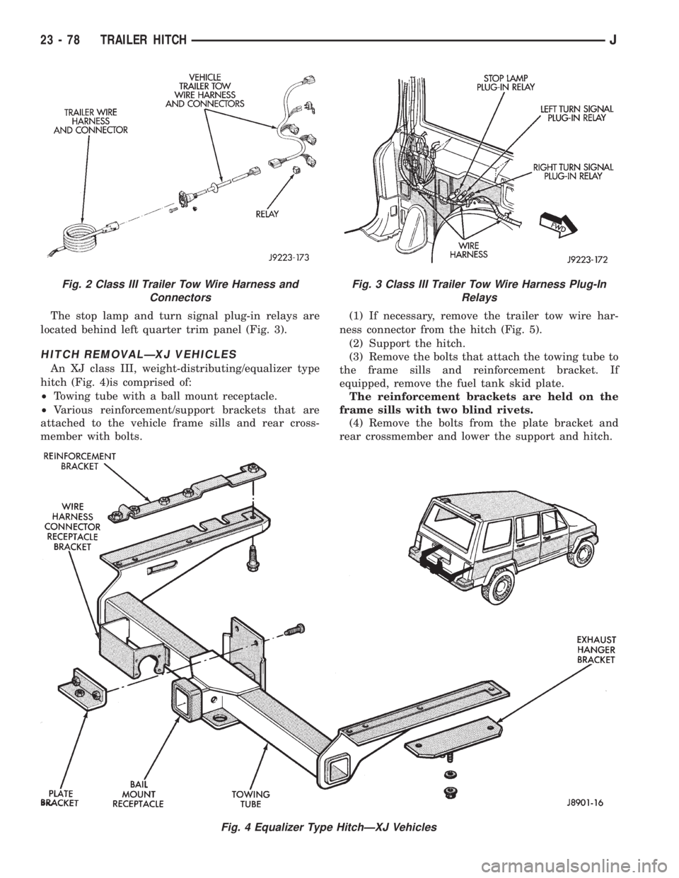
The stop lamp and turn signal plug-in relays are
located behind left quarter trim panel (Fig. 3).
HITCH REMOVALÐXJ VEHICLES
An XJ class III, weight-distributing/equalizer type
hitch (Fig. 4)is comprised of:
²Towing tube with a ball mount receptacle.
²Various reinforcement/support brackets that are
attached to the vehicle frame sills and rear cross-
member with bolts.(1) If necessary, remove the trailer tow wire har-
ness connector from the hitch (Fig. 5).
(2) Support the hitch.
(3) Remove the bolts that attach the towing tube to
the frame sills and reinforcement bracket. If
equipped, remove the fuel tank skid plate.
The reinforcement brackets are held on the
frame sills with two blind rivets.
(4) Remove the bolts from the plate bracket and
rear crossmember and lower the support and hitch.
Fig. 4 Equalizer Type HitchÐXJ Vehicles
Fig. 2 Class III Trailer Tow Wire Harness and
ConnectorsFig. 3 Class III Trailer Tow Wire Harness Plug-In
Relays
23 - 78 TRAILER HITCHJ
Page 1812 of 2198
INSTALLATIONÐXJ VEHICLES
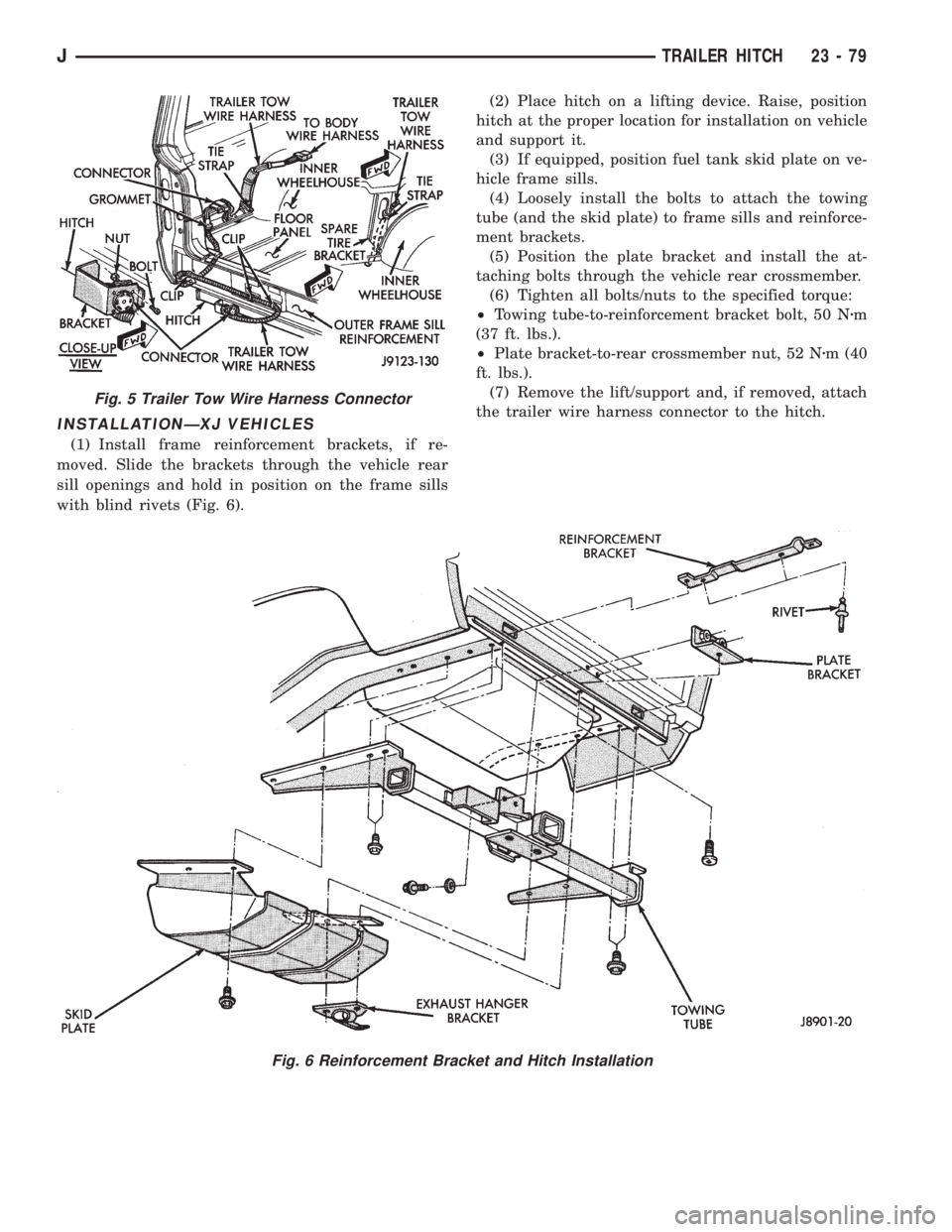
(1) Install frame reinforcement brackets, if re-
moved. Slide the brackets through the vehicle rear
sill openings and hold in position on the frame sills
with blind rivets (Fig. 6).(2) Place hitch on a lifting device. Raise, position
hitch at the proper location for installation on vehicle
and support it.
(3) If equipped, position fuel tank skid plate on ve-
hicle frame sills.
(4) Loosely install the bolts to attach the towing
tube (and the skid plate) to frame sills and reinforce-
ment brackets.
(5) Position the plate bracket and install the at-
taching bolts through the vehicle rear crossmember.
(6) Tighten all bolts/nuts to the specified torque:
²Towing tube-to-reinforcement bracket bolt, 50 Nzm
(37 ft. lbs.).
²Plate bracket-to-rear crossmember nut, 52 Nzm (40
ft. lbs.).
(7) Remove the lift/support and, if removed, attach
the trailer wire harness connector to the hitch.
Fig. 6 Reinforcement Bracket and Hitch Installation
Fig. 5 Trailer Tow Wire Harness Connector
JTRAILER HITCH 23 - 79
Page 1813 of 2198
INTERIOR COMPONENTS
INDEX
page page
Assist HandleÐXJ........................ 89
B/C-Pillar and Liftgate Pillar Trim CoversÐXJ.... 88
Bucket Seat Cushion and CoverÐXJ........... 81
Bucket Seat PlatformÐXJ................... 82
Bucket Seatback Cover and FrameÐXJ........ 81
Cargo BarrierÐXJ........................ 101
Cargo LampÐXJ......................... 94
Carpets and Floor MatsÐXJ................. 99
Dome LampÐXJ......................... 93
Front Bucket SeatsÐXJ.................... 81
Front Carpet/MatÐXJ...................... 99
Front Inner Scuff Plate/Cowl Side Trim PanelÐXJ . 86
Front Shoulder Belt/BuckleÐXJ............... 90
Full Floor ConsoleÐXJ..................... 95
HeadlinerÐXJ............................ 92
I/P Ash Receiver Tray LampÐXJ.............. 80
Instrument Cluster BezelÐXJ................ 80
Interior Trim Panels and Scuff PlatesÐXJ....... 84
Jack StorageÐXJ......................... 97
Keyless Entry ReceiverÐXJ................. 93Mini-Console with Floor ShiftÐXJ............. 94
Mini-Floor ConsoleÐXJ..................... 94
Outer Scuff PlatesÐXJ..................... 89
Overhead ConsoleÐXJ..................... 93
Parking Brake Handle CoverÐXJ............. 94
Quarter and Wheelhouse Trim PanelsÐXJ...... 87
Quarter Trim Panel ExtensionÐXJ............. 87
Rear Carpet/MatÐXJ..................... 100
Rear Seat Cushion CoverÐXJ............... 82
Rear Seat CushionÐXJ.................... 82
Rear Seatback CoverÐXJ................... 84
Rear Seatback Latch Striker and BumperÐXJ.... 84
Rear SeatbackÐXJ........................ 83
Rear Shoulder/Lap Belt/BuckleÐXJ............ 91
Sound BarÐXJ........................... 94
Spare Tire/Wheel Holddown and Floor
BracketsÐXJ........................... 98
SunvisorsÐXJ........................... 93
Windshield Side MoldingÐXJ................ 86
INSTRUMENT CLUSTER BEZELÐXJ
REMOVAL
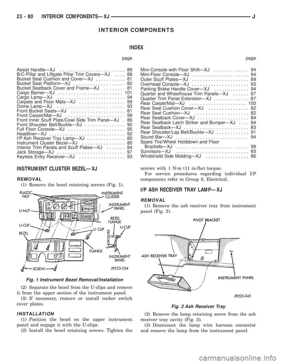
(1) Remove the bezel retaining screws (Fig. 1).
(2) Separate the bezel from the U-clips and remove
it from the upper section of the instrument panel.
(3) If necessary, remove or install rocker switch
cover plates.
INSTALLATION
(1) Position the bezel on the upper instrument
panel and engage it with the U-clips.
(2) Install the bezel retaining screws. Tighten thescrews with 1 Nzm (11 in-lbs) torque.
For service procedures regarding individual I/P
components refer to Group 8, Electrical.
I/P ASH RECEIVER TRAY LAMPÐXJ
REMOVAL
(1) Remove the ash receiver tray from instrument
panel (Fig. 2).
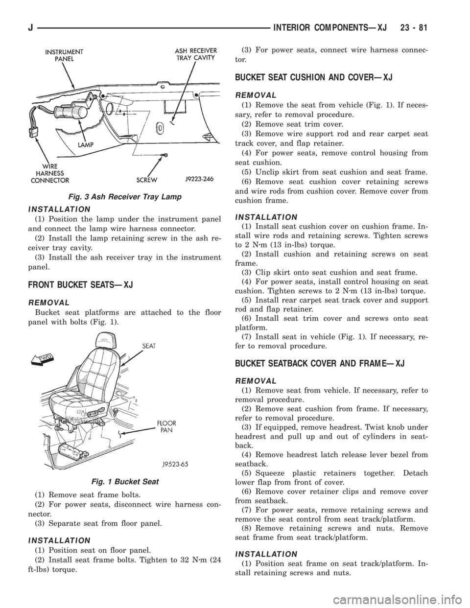
(2) Remove the lamp retaining screw from the ash
receiver tray cavity (Fig. 3).
(3) Disconnect the lamp wire harness connector
and remove the lamp from the instrument panel.
Fig. 1 Instrument Bezel Removal/Installation
Fig. 2 Ash Receiver Tray
23 - 80 INTERIOR COMPONENTSÐXJJ
Page 1814 of 2198
INSTALLATION
(1) Position the lamp under the instrument panel
and connect the lamp wire harness connector.
(2) Install the lamp retaining screw in the ash re-
ceiver tray cavity.
(3) Install the ash receiver tray in the instrument
panel.
FRONT BUCKET SEATSÐXJ
REMOVAL
Bucket seat platforms are attached to the floor
panel with bolts (Fig. 1).
(1) Remove seat frame bolts.
(2) For power seats, disconnect wire harness con-
nector.
(3) Separate seat from floor panel.
INSTALLATION
(1) Position seat on floor panel.
(2) Install seat frame bolts. Tighten to 32 Nzm (24
ft-lbs) torque.(3) For power seats, connect wire harness connec-
tor.
BUCKET SEAT CUSHION AND COVERÐXJ
REMOVAL
(1) Remove the seat from vehicle (Fig. 1). If neces-
sary, refer to removal procedure.
(2) Remove seat trim cover.
(3) Remove wire support rod and rear carpet seat
track cover, and flap retainer.
(4) For power seats, remove control housing from
seat cushion.
(5) Unclip skirt from seat cushion and seat frame.
(6) Remove seat cushion cover retaining screws
and wire rods from cushion cover. Remove cover from
cushion frame.
INSTALLATION
(1) Install seat cushion cover on cushion frame. In-
stall wire rods and retaining screws. Tighten screws
to2Nzm (13 in-lbs) torque.
(2) Install cushion and retaining screws on seat
frame.
(3) Clip skirt onto seat cushion and seat frame.
(4) For power seats, install control housing on seat
cushion. Tighten screws to 2 Nzm (13 in-lbs) torque.
(5) Install rear carpet seat track cover and support
rod and flap retainer.
(6) Install seat trim cover and screws onto seat
platform.
(7) Install seat in vehicle (Fig. 1). If necessary, re-
fer to removal procedure.
BUCKET SEATBACK COVER AND FRAMEÐXJ
REMOVAL
(1) Remove seat from vehicle. If necessary, refer to
removal procedure.
(2) Remove seat cushion from frame. If necessary,
refer to removal procedure.
(3) If equipped, remove headrest. Twist knob under
headrest and pull up and out of cylinders in seat-
back.
(4) Remove headrest latch release lever bezel from
seatback.
(5) Squeeze plastic retainers together. Detach
lower flap from front of cover.
(6) Remove cover retainer clips and remove cover
from seatback.
(7) For power seats, remove retaining screws and
remove the seat control from seat track/platform.
(8) Remove retaining screws and nuts. Remove
seat frame from seat track/platform.
INSTALLATION
(1) Position seat frame on seat track/platform. In-
stall retaining screws and nuts.
Fig. 3 Ash Receiver Tray Lamp
Fig. 1 Bucket Seat
JINTERIOR COMPONENTSÐXJ 23 - 81
Page 1815 of 2198
(2) For power seats, position seat control on seat
track/platform. Install retaining screws. Tighten
screws securely.
(3) Position cover on seatback. Install cover re-
tainer clips.
(4) Attach cover bottom elastic band or attach Vel-
cro flap to front of cover.
(5) Install seatback insert.
(6) Install headrest latch release lever bezel.
(7) Install headrest by pushing it down into seat-
back cylinders.
(8) Install cushion on frame. If necessary, refer to
installation procedure.
(9) Install seat in the vehicle. If necessary, refer to
the installation procedure.
(10) For power seats, test seat operation.
BUCKET SEAT PLATFORMÐXJ
REPLACEMENT
Bucket seat platforms are not repairable. If the
seat platform is damaged, replace platform as a unit.
REAR SEAT CUSHIONÐXJ
REMOVAL
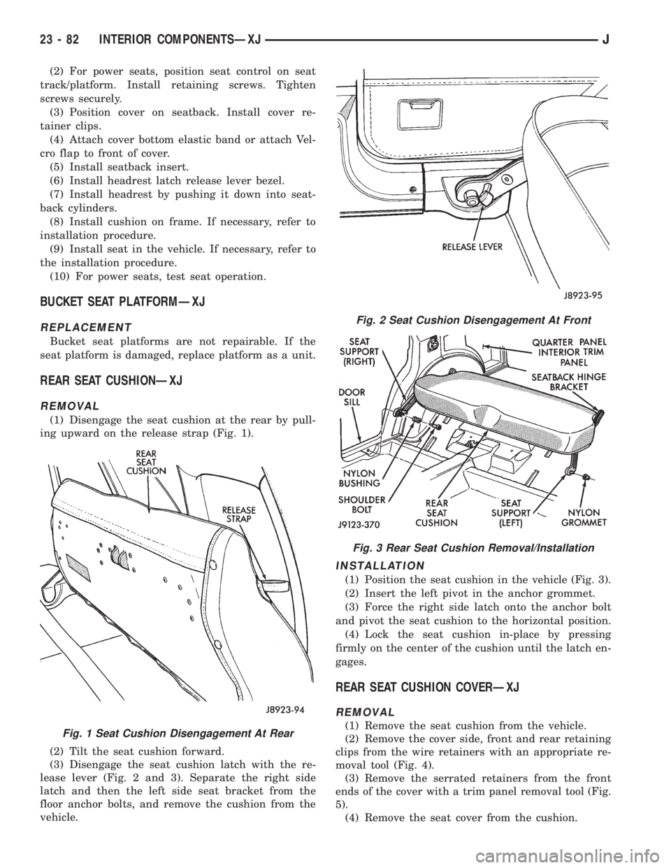
(1) Disengage the seat cushion at the rear by pull-
ing upward on the release strap (Fig. 1).
(2) Tilt the seat cushion forward.
(3) Disengage the seat cushion latch with the re-
lease lever (Fig. 2 and 3). Separate the right side
latch and then the left side seat bracket from the
floor anchor bolts, and remove the cushion from the
vehicle.
INSTALLATION
(1) Position the seat cushion in the vehicle (Fig. 3).
(2) Insert the left pivot in the anchor grommet.
(3) Force the right side latch onto the anchor bolt
and pivot the seat cushion to the horizontal position.
(4) Lock the seat cushion in-place by pressing
firmly on the center of the cushion until the latch en-
gages.
REAR SEAT CUSHION COVERÐXJ
REMOVAL
(1) Remove the seat cushion from the vehicle.
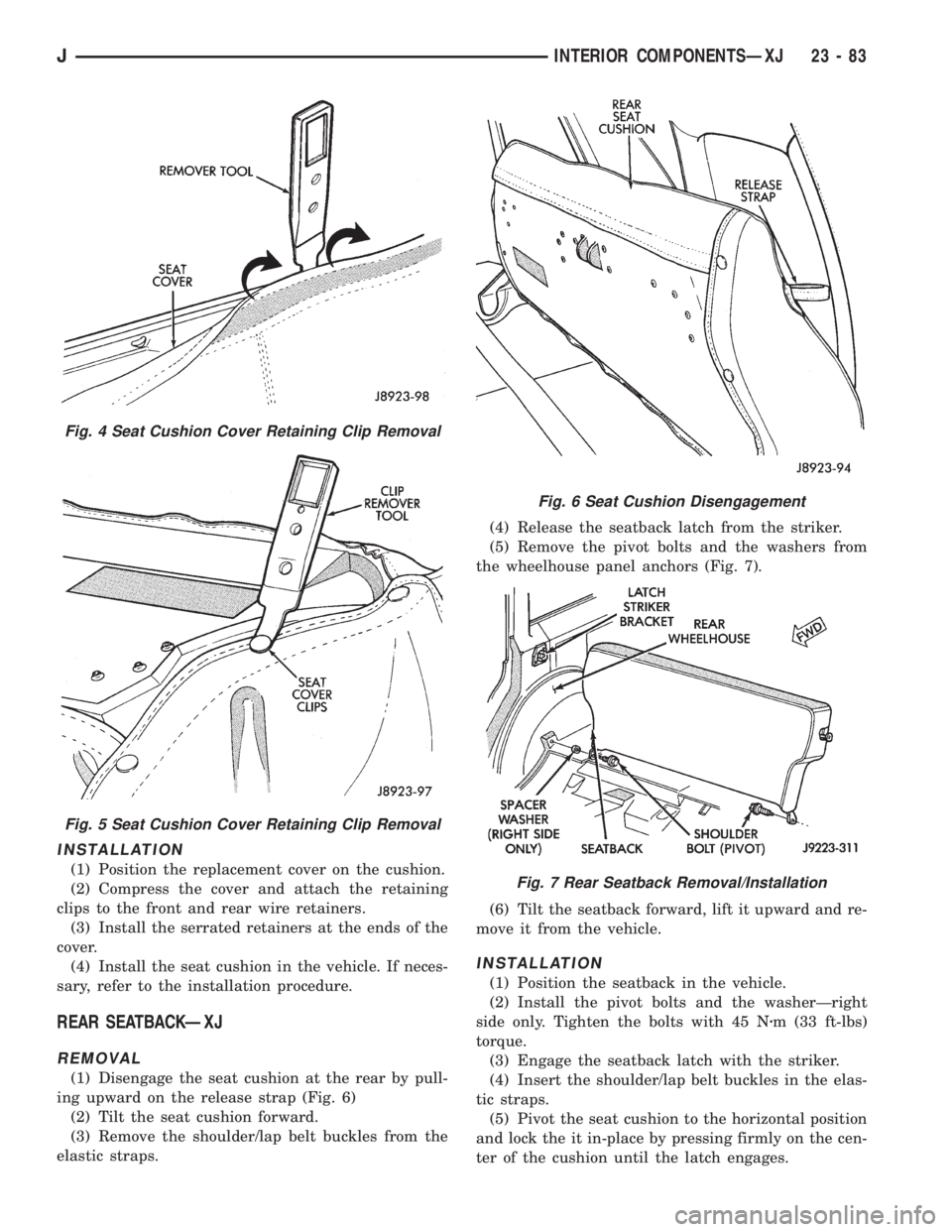
(2) Remove the cover side, front and rear retaining
clips from the wire retainers with an appropriate re-
moval tool (Fig. 4).
(3) Remove the serrated retainers from the front
ends of the cover with a trim panel removal tool (Fig.
5).
(4) Remove the seat cover from the cushion.Fig. 1 Seat Cushion Disengagement At Rear
Fig. 2 Seat Cushion Disengagement At Front
Fig. 3 Rear Seat Cushion Removal/Installation
23 - 82 INTERIOR COMPONENTSÐXJJ
Page 1816 of 2198
INSTALLATION
(1) Position the replacement cover on the cushion.
(2) Compress the cover and attach the retaining
clips to the front and rear wire retainers.
(3) Install the serrated retainers at the ends of the
cover.
(4) Install the seat cushion in the vehicle. If neces-
sary, refer to the installation procedure.
REAR SEATBACKÐXJ
REMOVAL
(1) Disengage the seat cushion at the rear by pull-
ing upward on the release strap (Fig. 6)
(2) Tilt the seat cushion forward.
(3) Remove the shoulder/lap belt buckles from the
elastic straps.(4) Release the seatback latch from the striker.
(5) Remove the pivot bolts and the washers from
the wheelhouse panel anchors (Fig. 7).
(6) Tilt the seatback forward, lift it upward and re-
move it from the vehicle.
INSTALLATION
(1) Position the seatback in the vehicle.
(2) Install the pivot bolts and the washerÐright
side only. Tighten the bolts with 45 Nzm (33 ft-lbs)
torque.
(3) Engage the seatback latch with the striker.
(4) Insert the shoulder/lap belt buckles in the elas-
tic straps.
(5) Pivot the seat cushion to the horizontal position
and lock the it in-place by pressing firmly on the cen-
ter of the cushion until the latch engages.
Fig. 4 Seat Cushion Cover Retaining Clip Removal
Fig. 5 Seat Cushion Cover Retaining Clip Removal
Fig. 6 Seat Cushion Disengagement
Fig. 7 Rear Seatback Removal/Installation
JINTERIOR COMPONENTSÐXJ 23 - 83
Page 1817 of 2198
REAR SEATBACK LATCH STRIKER AND BUMPERÐ
XJ
REMOVAL
(1) Disengage the seat cushion at the rear by pull-
ing upward on the release strap.
(2) Tilt the seat cushion forward.
(3) Release the seatback latch from the striker.
(4) Tilt the seatback forward for access to the
striker bracket.
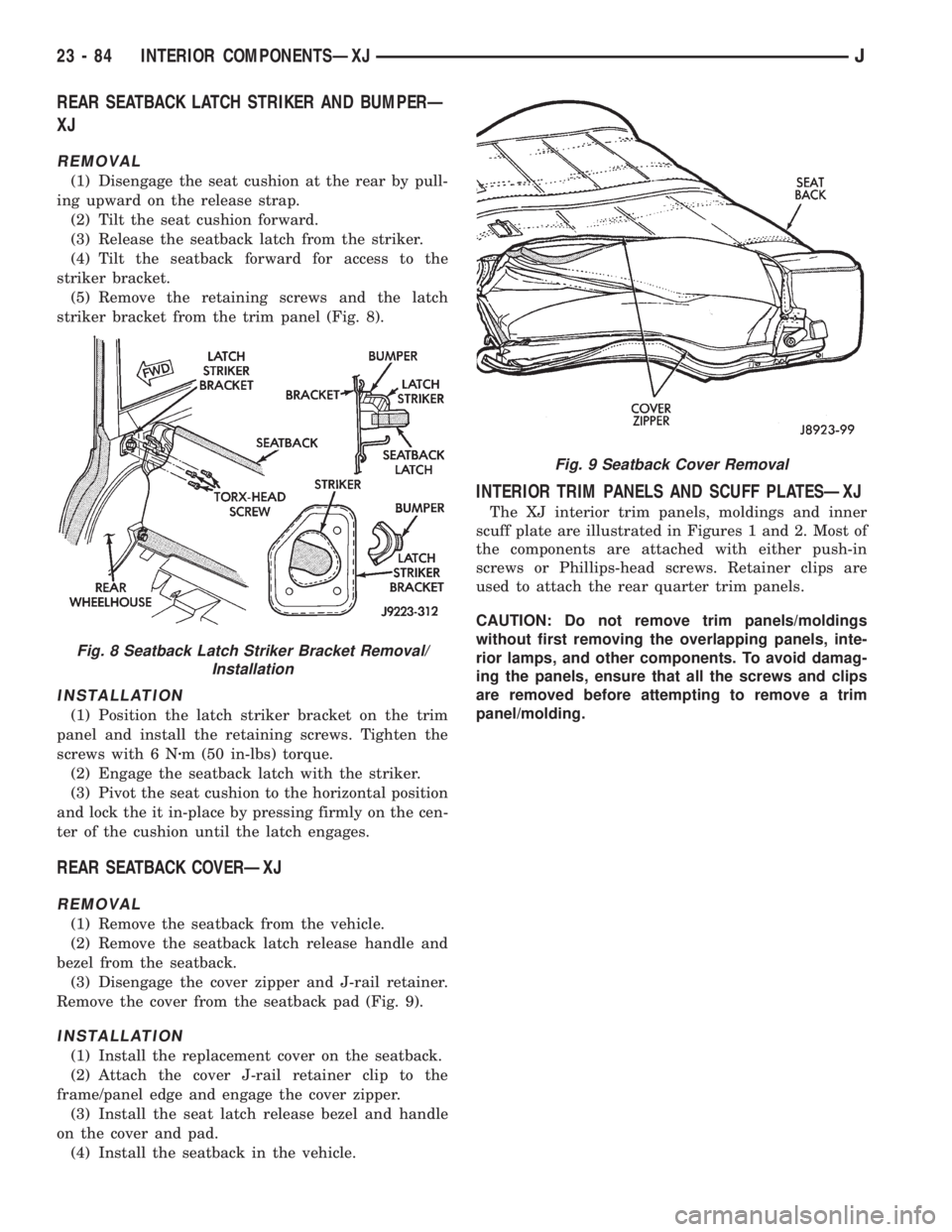
(5) Remove the retaining screws and the latch
striker bracket from the trim panel (Fig. 8).
INSTALLATION
(1) Position the latch striker bracket on the trim
panel and install the retaining screws. Tighten the
screws with 6 Nzm (50 in-lbs) torque.
(2) Engage the seatback latch with the striker.
(3) Pivot the seat cushion to the horizontal position
and lock the it in-place by pressing firmly on the cen-
ter of the cushion until the latch engages.
REAR SEATBACK COVERÐXJ
REMOVAL
(1) Remove the seatback from the vehicle.
(2) Remove the seatback latch release handle and
bezel from the seatback.
(3) Disengage the cover zipper and J-rail retainer.
Remove the cover from the seatback pad (Fig. 9).
INSTALLATION
(1) Install the replacement cover on the seatback.
(2) Attach the cover J-rail retainer clip to the
frame/panel edge and engage the cover zipper.
(3) Install the seat latch release bezel and handle
on the cover and pad.
(4) Install the seatback in the vehicle.
INTERIOR TRIM PANELS AND SCUFF PLATESÐXJ
The XJ interior trim panels, moldings and inner
scuff plate are illustrated in Figures 1 and 2. Most of
the components are attached with either push-in
screws or Phillips-head screws. Retainer clips are
used to attach the rear quarter trim panels.
CAUTION: Do not remove trim panels/moldings
without first removing the overlapping panels, inte-
rior lamps, and other components. To avoid damag-
ing the panels, ensure that all the screws and clips
are removed before attempting to remove a trim
panel/molding.
Fig. 8 Seatback Latch Striker Bracket Removal/
Installation
Fig. 9 Seatback Cover Removal
23 - 84 INTERIOR COMPONENTSÐXJJ
Page 1818 of 2198
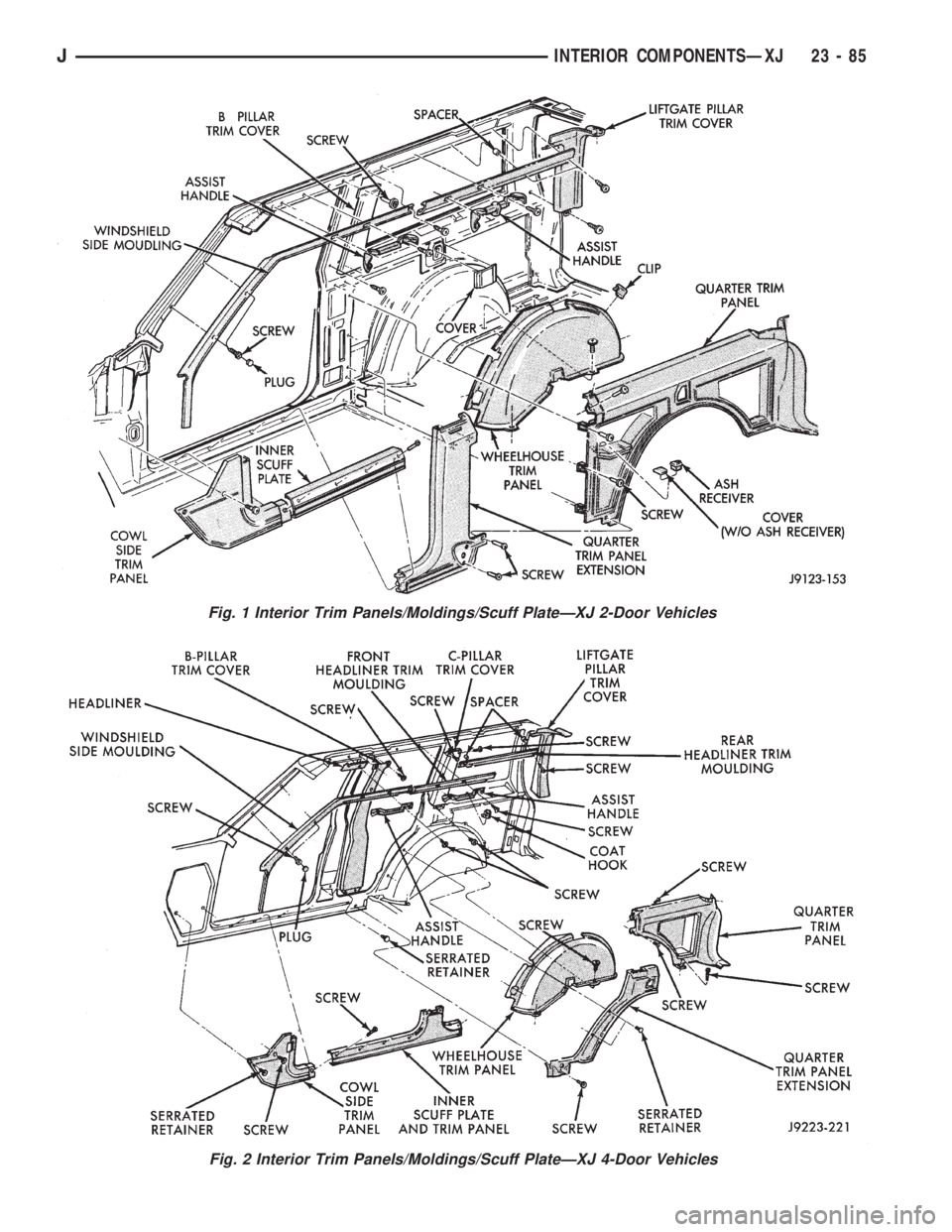
Fig. 1 Interior Trim Panels/Moldings/Scuff PlateÐXJ 2-Door Vehicles
Fig. 2 Interior Trim Panels/Moldings/Scuff PlateÐXJ 4-Door Vehicles
JINTERIOR COMPONENTSÐXJ 23 - 85
Page 1819 of 2198
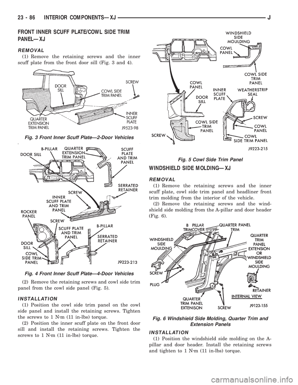
FRONT INNER SCUFF PLATE/COWL SIDE TRIM
PANELÐXJ
REMOVAL
(1) Remove the retaining screws and the inner
scuff plate from the front door sill (Fig. 3 and 4).
(2) Remove the retaining screws and cowl side trim
panel from the cowl side panel (Fig. 5).
INSTALLATION
(1) Position the cowl side trim panel on the cowl
side panel and install the retaining screws. Tighten
the screws to 1 Nzm (11 in-lbs) torque.
(2) Position the inner scuff plate on the front door
sill and install the retaining screws. Tighten the
screws to 1 Nzm (11 in-lbs) torque.
WINDSHIELD SIDE MOLDINGÐXJ
REMOVAL
(1) Remove the retaining screws and the inner
scuff plate, cowl side trim panel and headliner front
trim molding from the interior of the vehicle.
(2) Remove the retaining screws and the wind-
shield side molding from the A-pillar and door header
(Fig. 6).
INSTALLATION
(1) Position the windshield side molding on the A-
pillar and door header. Install the retaining screws
and tighten to 1 Nzm (11 in-lbs) torque.
Fig. 3 Front Inner Scuff PlateÐ2-Door Vehicles
Fig. 4 Front Inner Scuff PlateÐ4-Door Vehicles
Fig. 5 Cowl Side Trim Panel
Fig. 6 Windshield Side Molding, Quarter Trim and
Extension Panels
23 - 86 INTERIOR COMPONENTSÐXJJ
Page 1820 of 2198
(2) Install the headliner front trim molding, the
cowl side trim panel and the inner scuff plate in the
interior of the vehicle. Tighten the retaining screw to
1Nzm (11 in-lbs) torque.
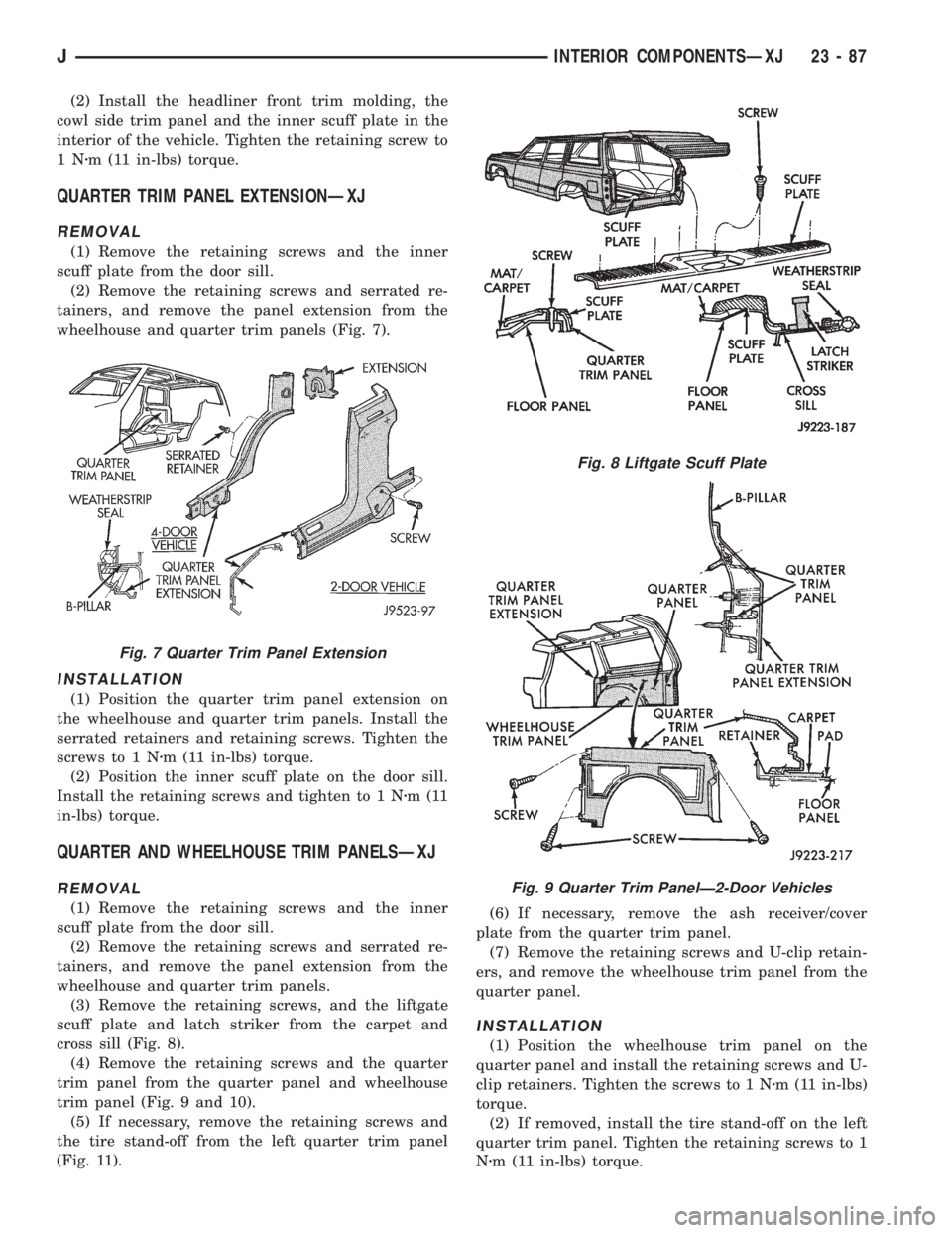
QUARTER TRIM PANEL EXTENSIONÐXJ
REMOVAL
(1) Remove the retaining screws and the inner
scuff plate from the door sill.
(2) Remove the retaining screws and serrated re-
tainers, and remove the panel extension from the
wheelhouse and quarter trim panels (Fig. 7).
INSTALLATION
(1) Position the quarter trim panel extension on
the wheelhouse and quarter trim panels. Install the
serrated retainers and retaining screws. Tighten the
screws to 1 Nzm (11 in-lbs) torque.
(2) Position the inner scuff plate on the door sill.
Install the retaining screws and tighten to 1 Nzm(11
in-lbs) torque.
QUARTER AND WHEELHOUSE TRIM PANELSÐXJ
REMOVAL
(1) Remove the retaining screws and the inner
scuff plate from the door sill.
(2) Remove the retaining screws and serrated re-
tainers, and remove the panel extension from the
wheelhouse and quarter trim panels.
(3) Remove the retaining screws, and the liftgate
scuff plate and latch striker from the carpet and
cross sill (Fig. 8).
(4) Remove the retaining screws and the quarter
trim panel from the quarter panel and wheelhouse
trim panel (Fig. 9 and 10).
(5) If necessary, remove the retaining screws and
the tire stand-off from the left quarter trim panel
(Fig. 11).(6) If necessary, remove the ash receiver/cover
plate from the quarter trim panel.
(7) Remove the retaining screws and U-clip retain-
ers, and remove the wheelhouse trim panel from the
quarter panel.
INSTALLATION
(1) Position the wheelhouse trim panel on the
quarter panel and install the retaining screws and U-
clip retainers. Tighten the screws to 1 Nzm (11 in-lbs)
torque.
(2) If removed, install the tire stand-off on the left
quarter trim panel. Tighten the retaining screws to 1
Nzm (11 in-lbs) torque.
Fig. 7 Quarter Trim Panel Extension
Fig. 8 Liftgate Scuff Plate
Fig. 9 Quarter Trim PanelÐ2-Door Vehicles
JINTERIOR COMPONENTSÐXJ 23 - 87