JEEP CHEROKEE 1995 Service Repair Manual
Manufacturer: JEEP, Model Year: 1995, Model line: CHEROKEE, Model: JEEP CHEROKEE 1995Pages: 2198, PDF Size: 82.83 MB
Page 1821 of 2198
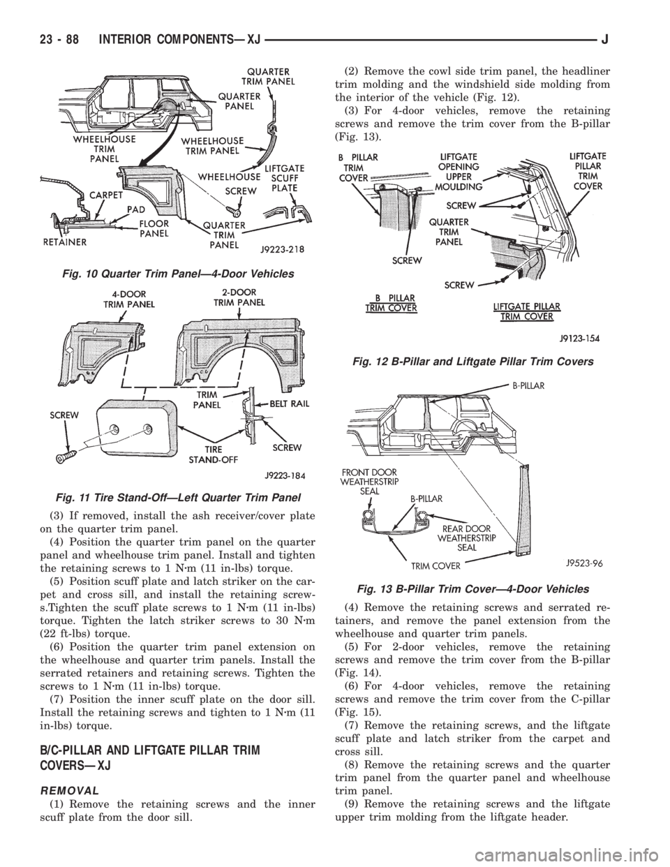
(3) If removed, install the ash receiver/cover plate
on the quarter trim panel.
(4) Position the quarter trim panel on the quarter
panel and wheelhouse trim panel. Install and tighten
the retaining screws to 1 Nzm (11 in-lbs) torque.
(5) Position scuff plate and latch striker on the car-
pet and cross sill, and install the retaining screw-
s.Tighten the scuff plate screws to 1 Nzm (11 in-lbs)
torque. Tighten the latch striker screws to 30 Nzm
(22 ft-lbs) torque.
(6) Position the quarter trim panel extension on
the wheelhouse and quarter trim panels. Install the
serrated retainers and retaining screws. Tighten the
screws to 1 Nzm (11 in-lbs) torque.
(7) Position the inner scuff plate on the door sill.
Install the retaining screws and tighten to 1 Nzm(11
in-lbs) torque.
B/C-PILLAR AND LIFTGATE PILLAR TRIM
COVERSÐXJ
REMOVAL
(1) Remove the retaining screws and the inner
scuff plate from the door sill.(2) Remove the cowl side trim panel, the headliner
trim molding and the windshield side molding from
the interior of the vehicle (Fig. 12).
(3) For 4-door vehicles, remove the retaining
screws and remove the trim cover from the B-pillar
(Fig. 13).
(4) Remove the retaining screws and serrated re-
tainers, and remove the panel extension from the
wheelhouse and quarter trim panels.
(5) For 2-door vehicles, remove the retaining
screws and remove the trim cover from the B-pillar
(Fig. 14).
(6) For 4-door vehicles, remove the retaining
screws and remove the trim cover from the C-pillar
(Fig. 15).
(7) Remove the retaining screws, and the liftgate
scuff plate and latch striker from the carpet and
cross sill.
(8) Remove the retaining screws and the quarter
trim panel from the quarter panel and wheelhouse
trim panel.
(9) Remove the retaining screws and the liftgate
upper trim molding from the liftgate header.
Fig. 10 Quarter Trim PanelÐ4-Door Vehicles
Fig. 11 Tire Stand-OffÐLeft Quarter Trim Panel
Fig. 12 B-Pillar and Liftgate Pillar Trim Covers
Fig. 13 B-Pillar Trim CoverÐ4-Door Vehicles
23 - 88 INTERIOR COMPONENTSÐXJJ
Page 1822 of 2198
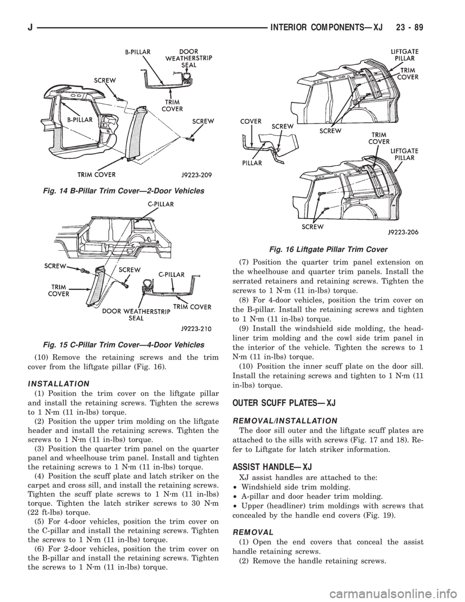
(10) Remove the retaining screws and the trim
cover from the liftgate pillar (Fig. 16).
INSTALLATION
(1) Position the trim cover on the liftgate pillar
and install the retaining screws. Tighten the screws
to1Nzm (11 in-lbs) torque.
(2) Position the upper trim molding on the liftgate
header and install the retaining screws. Tighten the
screws to 1 Nzm (11 in-lbs) torque.
(3) Position the quarter trim panel on the quarter
panel and wheelhouse trim panel. Install and tighten
the retaining screws to 1 Nzm (11 in-lbs) torque.
(4) Position the scuff plate and latch striker on the
carpet and cross sill, and install the retaining screws.
Tighten the scuff plate screws to 1 Nzm (11 in-lbs)
torque. Tighten the latch striker screws to 30 Nzm
(22 ft-lbs) torque.
(5) For 4-door vehicles, position the trim cover on
the C-pillar and install the retaining screws. Tighten
the screws to 1 Nzm (11 in-lbs) torque.
(6) For 2-door vehicles, position the trim cover on
the B-pillar and install the retaining screws. Tighten
the screws to 1 Nzm (11 in-lbs) torque.(7) Position the quarter trim panel extension on
the wheelhouse and quarter trim panels. Install the
serrated retainers and retaining screws. Tighten the
screws to 1 Nzm (11 in-lbs) torque.
(8) For 4-door vehicles, position the trim cover on
the B-pillar. Install the retaining screws and tighten
to1Nzm (11 in-lbs) torque.
(9) Install the windshield side molding, the head-
liner trim molding and the cowl side trim panel in
the interior of the vehicle. Tighten the screws to 1
Nzm (11 in-lbs) torque.
(10) Position the inner scuff plate on the door sill.
Install the retaining screws and tighten to 1 Nzm(11
in-lbs) torque.
OUTER SCUFF PLATESÐXJ
REMOVAL/INSTALLATION
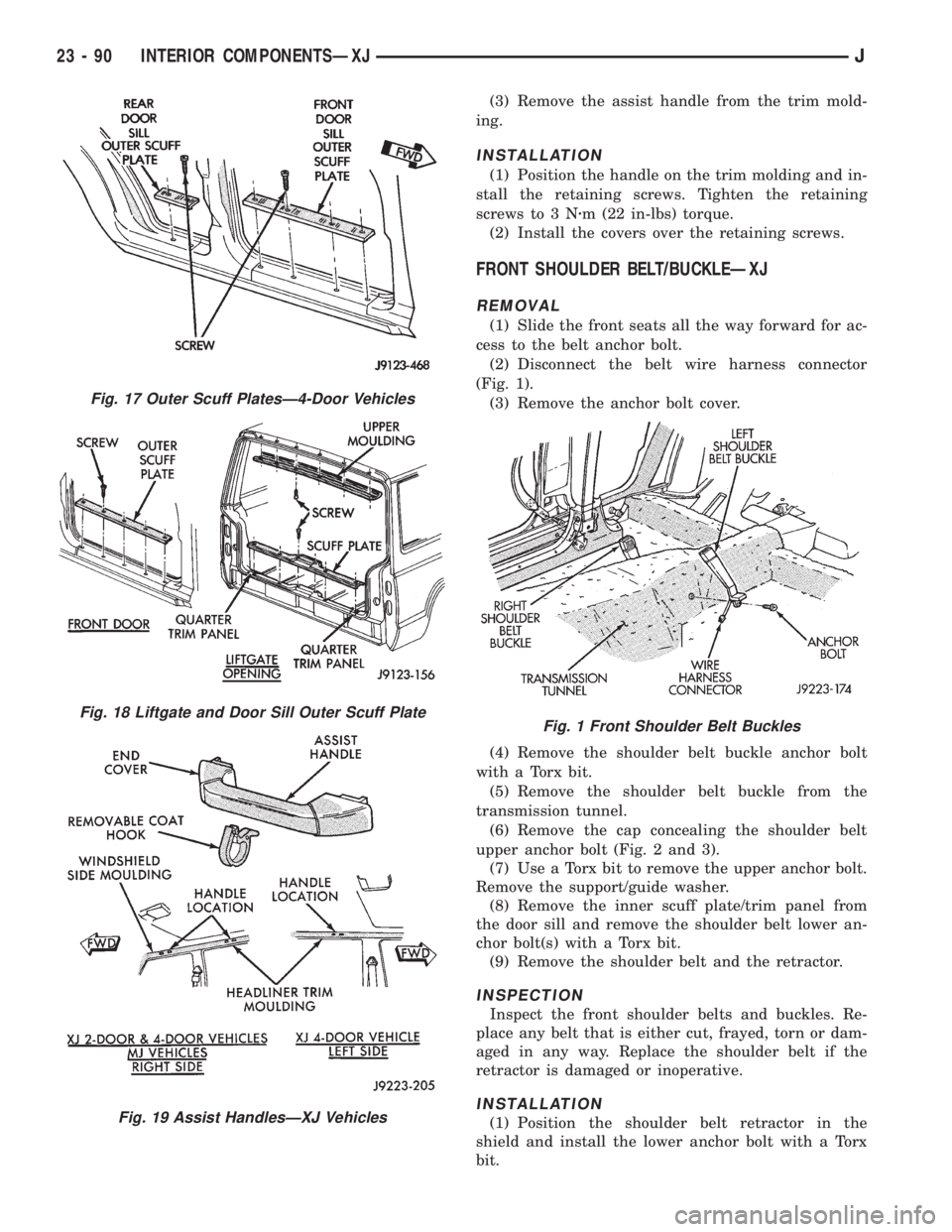
The door sill outer and the liftgate scuff plates are
attached to the sills with screws (Fig. 17 and 18). Re-
fer to Liftgate for latch striker information.
ASSIST HANDLEÐXJ
XJ assist handles are attached to the:
²Windshield side trim molding.
²A-pillar and door header trim molding.
²Upper (headliner) trim moldings with screws that
concealed by the handle end covers (Fig. 19).
REMOVAL
(1) Open the end covers that conceal the assist
handle retaining screws.
(2) Remove the handle retaining screws.
Fig. 14 B-Pillar Trim CoverÐ2-Door Vehicles
Fig. 15 C-Pillar Trim CoverÐ4-Door Vehicles
Fig. 16 Liftgate Pillar Trim Cover
JINTERIOR COMPONENTSÐXJ 23 - 89
Page 1823 of 2198
(3) Remove the assist handle from the trim mold-
ing.
INSTALLATION
(1) Position the handle on the trim molding and in-
stall the retaining screws. Tighten the retaining
screws to 3 Nzm (22 in-lbs) torque.
(2) Install the covers over the retaining screws.
FRONT SHOULDER BELT/BUCKLEÐXJ
REMOVAL
(1) Slide the front seats all the way forward for ac-
cess to the belt anchor bolt.
(2) Disconnect the belt wire harness connector
(Fig. 1).
(3) Remove the anchor bolt cover.
(4) Remove the shoulder belt buckle anchor bolt
with a Torx bit.
(5) Remove the shoulder belt buckle from the
transmission tunnel.
(6) Remove the cap concealing the shoulder belt
upper anchor bolt (Fig. 2 and 3).
(7) Use a Torx bit to remove the upper anchor bolt.
Remove the support/guide washer.
(8) Remove the inner scuff plate/trim panel from
the door sill and remove the shoulder belt lower an-
chor bolt(s) with a Torx bit.
(9) Remove the shoulder belt and the retractor.
INSPECTION
Inspect the front shoulder belts and buckles. Re-
place any belt that is either cut, frayed, torn or dam-
aged in any way. Replace the shoulder belt if the
retractor is damaged or inoperative.
INSTALLATION
(1) Position the shoulder belt retractor in the
shield and install the lower anchor bolt with a Torx
bit.
Fig. 17 Outer Scuff PlatesÐ4-Door Vehicles
Fig. 18 Liftgate and Door Sill Outer Scuff Plate
Fig. 19 Assist HandlesÐXJ Vehicles
Fig. 1 Front Shoulder Belt Buckles
23 - 90 INTERIOR COMPONENTSÐXJJ
Page 1824 of 2198
(2) Position the support/guide washer and shoulder
belt upper anchor plate on the trim panel. Install the
upper anchor bolt with a Torx bit.
(3) Tighten the upper and lower anchor bolts to 41
Nzm (30 ft-lbs) torque.
(4) Install the door sill inner scuff plate/trim panel
and install the cap over the upper anchor bolt.
(5) Install the shoulder belt buckle and anchor
bolt. Connect the wire harness connectors. Tighten
the buckle anchor bolt to 41 Nzm (30 ft-lbs) torque.
(6) Position the cover over the anchor bolt.
REAR SHOULDER/LAP BELT/BUCKLEÐXJ
REMOVAL
(1) Pull the rear seat release strap and tilt the
complete seat forward.
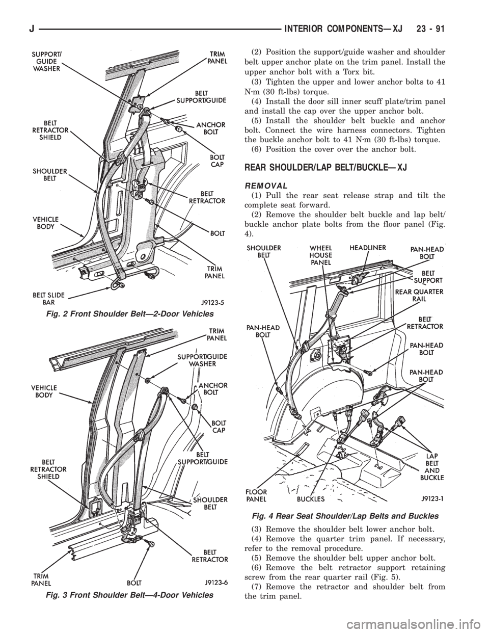
(2) Remove the shoulder belt buckle and lap belt/
buckle anchor plate bolts from the floor panel (Fig.
4).
(3) Remove the shoulder belt lower anchor bolt.
(4) Remove the quarter trim panel. If necessary,
refer to the removal procedure.
(5) Remove the shoulder belt upper anchor bolt.
(6) Remove the belt retractor support retaining
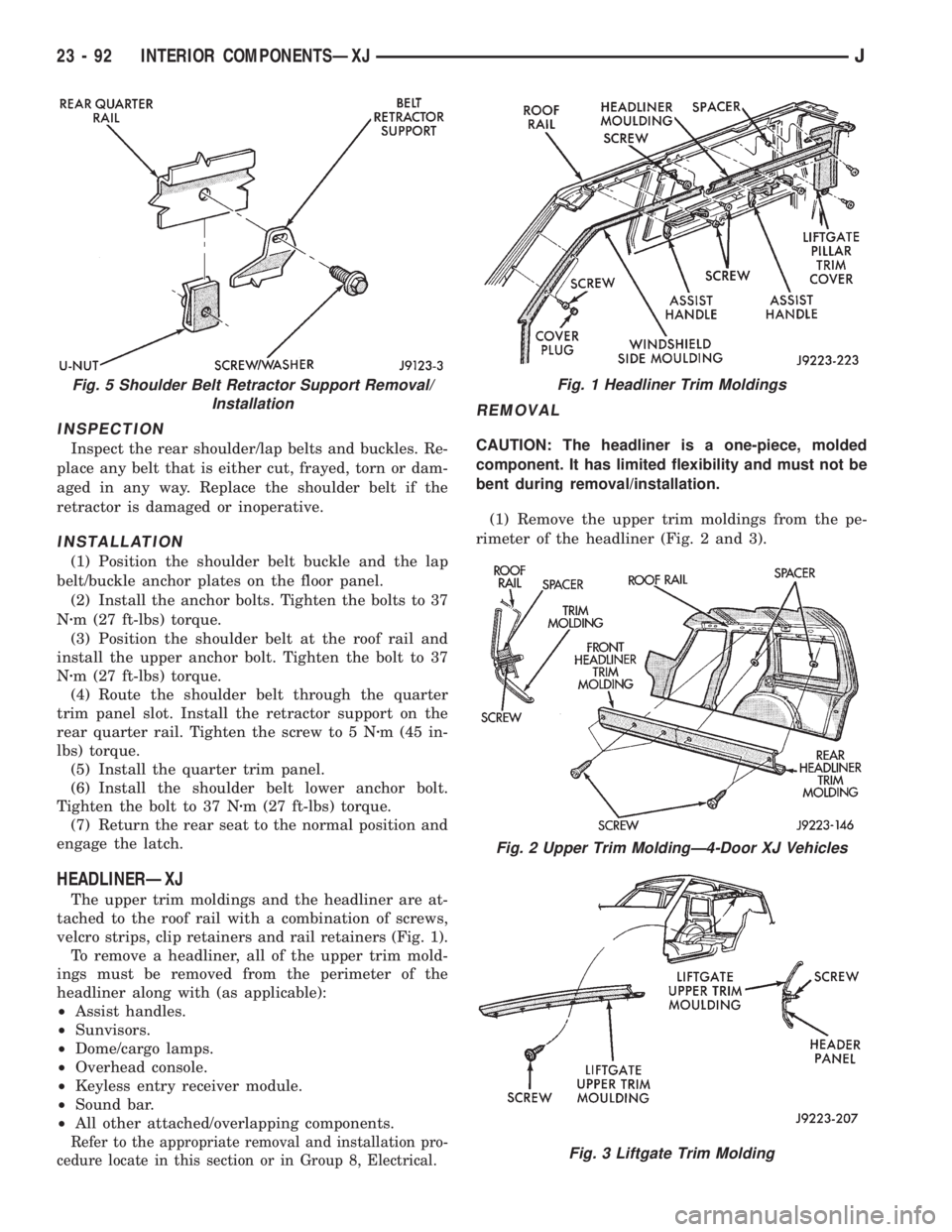
screw from the rear quarter rail (Fig. 5).
(7) Remove the retractor and shoulder belt from
the trim panel.
Fig. 2 Front Shoulder BeltÐ2-Door Vehicles
Fig. 3 Front Shoulder BeltÐ4-Door Vehicles
Fig. 4 Rear Seat Shoulder/Lap Belts and Buckles
JINTERIOR COMPONENTSÐXJ 23 - 91
Page 1825 of 2198
INSPECTION
Inspect the rear shoulder/lap belts and buckles. Re-
place any belt that is either cut, frayed, torn or dam-
aged in any way. Replace the shoulder belt if the
retractor is damaged or inoperative.
INSTALLATION
(1) Position the shoulder belt buckle and the lap
belt/buckle anchor plates on the floor panel.
(2) Install the anchor bolts. Tighten the bolts to 37
Nzm (27 ft-lbs) torque.
(3) Position the shoulder belt at the roof rail and
install the upper anchor bolt. Tighten the bolt to 37
Nzm (27 ft-lbs) torque.
(4) Route the shoulder belt through the quarter
trim panel slot. Install the retractor support on the
rear quarter rail. Tighten the screw to 5 Nzm (45 in-
lbs) torque.
(5) Install the quarter trim panel.
(6) Install the shoulder belt lower anchor bolt.
Tighten the bolt to 37 Nzm (27 ft-lbs) torque.
(7) Return the rear seat to the normal position and
engage the latch.
HEADLINERÐXJ
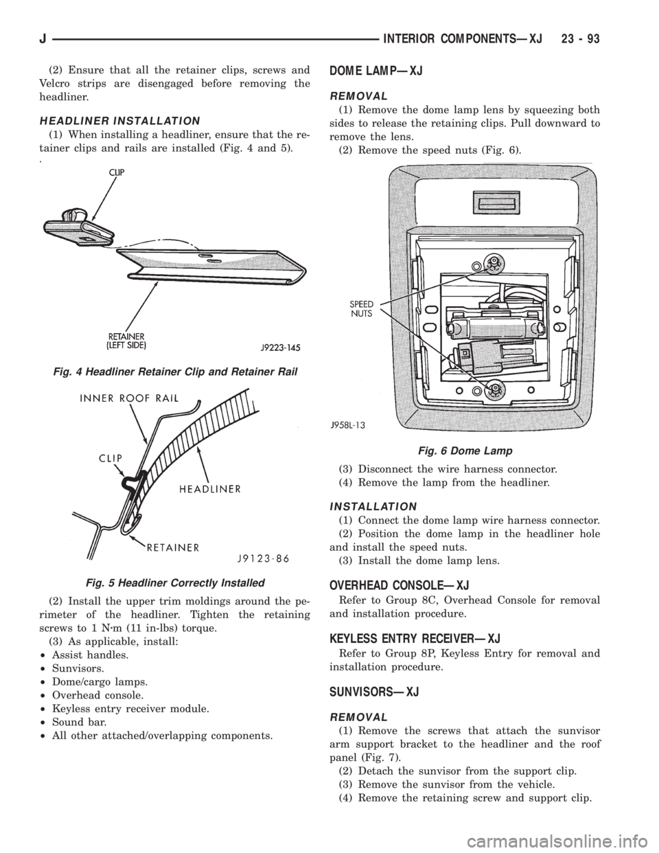
The upper trim moldings and the headliner are at-
tached to the roof rail with a combination of screws,
velcro strips, clip retainers and rail retainers (Fig. 1).
To remove a headliner, all of the upper trim mold-
ings must be removed from the perimeter of the
headliner along with (as applicable):
²Assist handles.
²Sunvisors.
²Dome/cargo lamps.
²Overhead console.
²Keyless entry receiver module.
²Sound bar.
²All other attached/overlapping components.
Refer to the appropriate removal and installation pro-
cedure locate in this section or in Group 8, Electrical.
REMOVAL
CAUTION: The headliner is a one-piece, molded
component. It has limited flexibility and must not be
bent during removal/installation.
(1) Remove the upper trim moldings from the pe-
rimeter of the headliner (Fig. 2 and 3).
Fig. 5 Shoulder Belt Retractor Support Removal/
InstallationFig. 1 Headliner Trim Moldings
Fig. 2 Upper Trim MoldingÐ4-Door XJ Vehicles
Fig. 3 Liftgate Trim Molding
23 - 92 INTERIOR COMPONENTSÐXJJ
Page 1826 of 2198
(2) Ensure that all the retainer clips, screws and
Velcro strips are disengaged before removing the
headliner.
HEADLINER INSTALLATION
(1) When installing a headliner, ensure that the re-
tainer clips and rails are installed (Fig. 4 and 5).
(2) Install the upper trim moldings around the pe-
rimeter of the headliner. Tighten the retaining
screws to 1 Nzm (11 in-lbs) torque.
(3) As applicable, install:
²Assist handles.
²Sunvisors.
²Dome/cargo lamps.
²Overhead console.
²Keyless entry receiver module.
²Sound bar.
²All other attached/overlapping components.
DOME LAMPÐXJ
REMOVAL
(1) Remove the dome lamp lens by squeezing both
sides to release the retaining clips. Pull downward to
remove the lens.
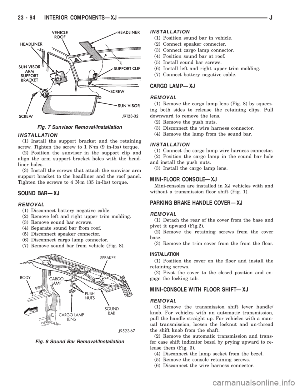
(2) Remove the speed nuts (Fig. 6).
(3) Disconnect the wire harness connector.
(4) Remove the lamp from the headliner.
INSTALLATION
(1) Connect the dome lamp wire harness connector.
(2) Position the dome lamp in the headliner hole
and install the speed nuts.
(3) Install the dome lamp lens.
OVERHEAD CONSOLEÐXJ
Refer to Group 8C, Overhead Console for removal
and installation procedure.
KEYLESS ENTRY RECEIVERÐXJ
Refer to Group 8P, Keyless Entry for removal and
installation procedure.
SUNVISORSÐXJ
REMOVAL
(1) Remove the screws that attach the sunvisor
arm support bracket to the headliner and the roof
panel (Fig. 7).
(2) Detach the sunvisor from the support clip.
(3) Remove the sunvisor from the vehicle.
(4) Remove the retaining screw and support clip.
Fig. 4 Headliner Retainer Clip and Retainer Rail
Fig. 5 Headliner Correctly Installed
Fig. 6 Dome Lamp
JINTERIOR COMPONENTSÐXJ 23 - 93
Page 1827 of 2198
INSTALLATION
(1) Install the support bracket and the retaining
screw. Tighten the screw to 1 Nzm (9 in-lbs) torque.
(2) Position the sunvisor in the support clip and
align the arm support bracket holes with the head-
liner holes.
(3) Install the screws that attach the sunvisor arm
support bracket to the headliner and the roof panel.
Tighten the screws to 4 Nzm (35 in-lbs) torque.
SOUND BARÐXJ
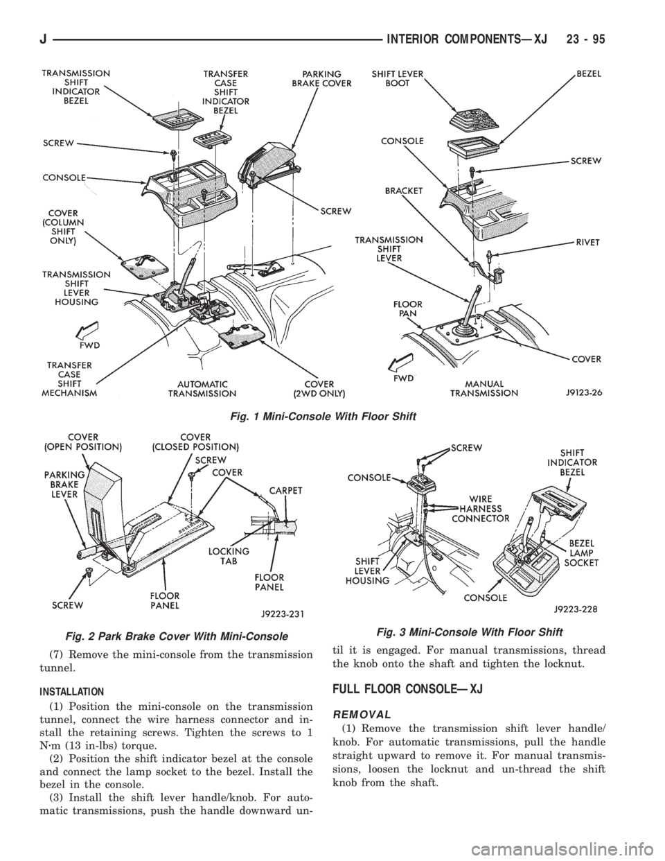
REMOVAL
(1) Disconnect battery negative cable.
(2) Remove left and right upper trim molding.
(3) Remove sound bar screws.
(4) Separate sound bar from roof.
(5) Disconnect speaker connector.
(6) Disconnect cargo lamp connector.
(7) Remove sound bar from vehicle (Fig. 8).
INSTALLATION
(1) Position sound bar in vehicle.
(2) Connect speaker connecter.
(3) Connect cargo lamp connector.
(4) Position sound bar at roof.
(5) Install sound bar screws.
(6) Install left and right upper trim molding.
(7) Connect battery negative cable.
CARGO LAMPÐXJ
REMOVAL
(1) Remove the cargo lamp lens (Fig. 8) by squeez-
ing both sides to release the retaining clips. Pull
downward to remove the lens.
(2) Remove the push nuts.
(3) Disconnect the wire harness connector.
(4) Remove the lamp from the sound bar.
INSTALLATION
(1) Connect the cargo lamp wire harness connector.
(2) Position the cargo lamp in the sound bar hole
and install the push nuts.
(3) Install the cargo lamp lens.
MINI-FLOOR CONSOLEÐXJ
Mini-consoles are installed in XJ vehicles with and
without a transmission floor shift (Fig. 1).
PARKING BRAKE HANDLE COVERÐXJ
REMOVAL
(1) Detach the rear of the cover from the base and
pivot it upward (Fig.2).
(2) Remove the retaining screws from the cover
base.
(3) Remove the trim cover from the from the floor.
INSTALLATION
(1) Position the cover on the floor and install the
retaining screws.
(2) Pivot the cover to the closed position and en-
gage the locking tab.
MINI-CONSOLE WITH FLOOR SHIFTÐXJ
REMOVAL
(1) Remove the transmission shift lever handle/
knob. For vehicles with an automatic transmission,
pull the handle straight up. For vehicles with a man-
ual transmission, loosen the locknut and un-thread
the shift knob from the shaft.
(2) Remove the automatic transmission and trans-
fer case shift indicator bezel by prying upward to re-
lease them (Fig. 3).
(4) Disconnect the lamp socket from the bezel.
(5) Remove the console retaining screws.
(6) Disconnect the wire harness connector.
Fig. 7 Sunvisor Removal/Installation
Fig. 8 Sound Bar Removal/Installation
23 - 94 INTERIOR COMPONENTSÐXJJ
Page 1828 of 2198
(7) Remove the mini-console from the transmission
tunnel.
INSTALLATION
(1) Position the mini-console on the transmission
tunnel, connect the wire harness connector and in-
stall the retaining screws. Tighten the screws to 1
Nzm (13 in-lbs) torque.
(2) Position the shift indicator bezel at the console
and connect the lamp socket to the bezel. Install the
bezel in the console.
(3) Install the shift lever handle/knob. For auto-
matic transmissions, push the handle downward un-til it is engaged. For manual transmissions, thread
the knob onto the shaft and tighten the locknut.
FULL FLOOR CONSOLEÐXJ
REMOVAL
(1) Remove the transmission shift lever handle/
knob. For automatic transmissions, pull the handle
straight upward to remove it. For manual transmis-
sions, loosen the locknut and un-thread the shift
knob from the shaft.
Fig. 1 Mini-Console With Floor Shift
Fig. 2 Park Brake Cover With Mini-ConsoleFig. 3 Mini-Console With Floor Shift
JINTERIOR COMPONENTSÐXJ 23 - 95
Page 1829 of 2198
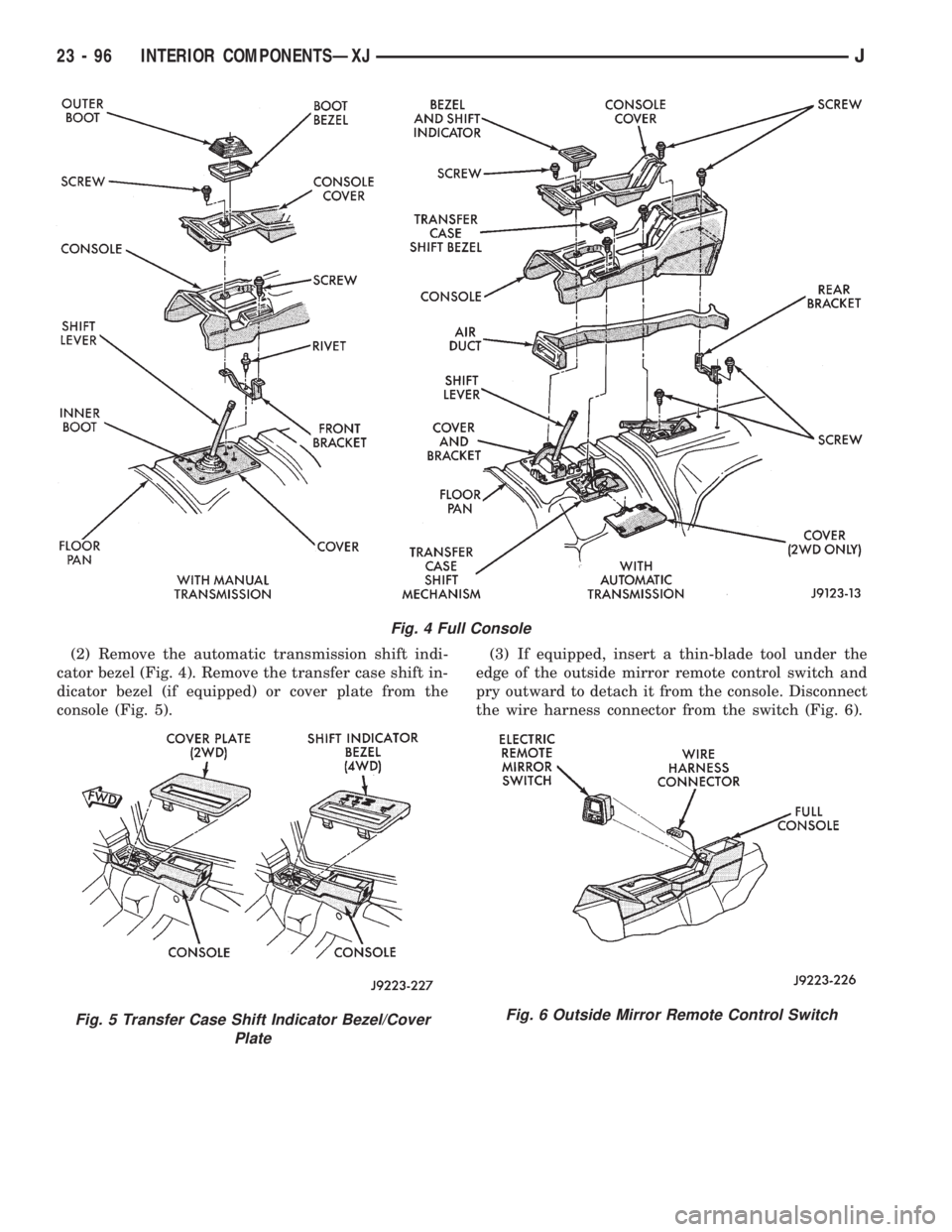
(2) Remove the automatic transmission shift indi-
cator bezel (Fig. 4). Remove the transfer case shift in-
dicator bezel (if equipped) or cover plate from the
console (Fig. 5).(3) If equipped, insert a thin-blade tool under the
edge of the outside mirror remote control switch and
pry outward to detach it from the console. Disconnect
the wire harness connector from the switch (Fig. 6).
Fig. 4 Full Console
Fig. 5 Transfer Case Shift Indicator Bezel/Cover
PlateFig. 6 Outside Mirror Remote Control Switch
23 - 96 INTERIOR COMPONENTSÐXJJ
Page 1830 of 2198
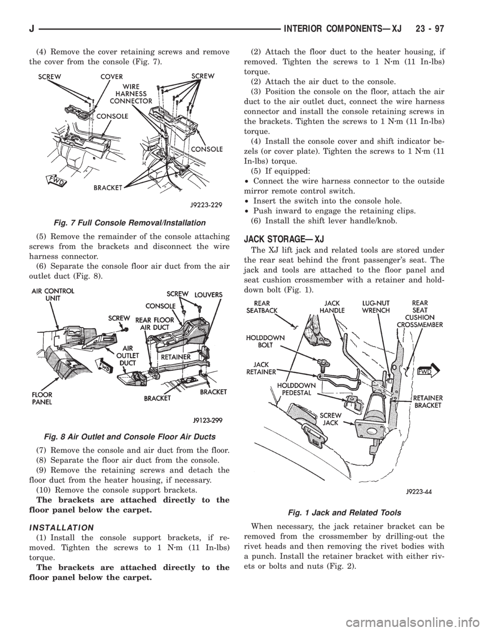
(4) Remove the cover retaining screws and remove
the cover from the console (Fig. 7).
(5) Remove the remainder of the console attaching
screws from the brackets and disconnect the wire
harness connector.
(6) Separate the console floor air duct from the air
outlet duct (Fig. 8).
(7) Remove the console and air duct from the floor.
(8) Separate the floor air duct from the console.
(9) Remove the retaining screws and detach the
floor duct from the heater housing, if necessary.
(10) Remove the console support brackets.
The brackets are attached directly to the
floor panel below the carpet.
INSTALLATION
(1) Install the console support brackets, if re-
moved. Tighten the screws to 1 Nzm (11 In-lbs)
torque.
The brackets are attached directly to the
floor panel below the carpet.(2) Attach the floor duct to the heater housing, if
removed. Tighten the screws to 1 Nzm (11 In-lbs)
torque.
(2) Attach the air duct to the console.
(3) Position the console on the floor, attach the air
duct to the air outlet duct, connect the wire harness
connector and install the console retaining screws in
the brackets. Tighten the screws to 1 Nzm (11 In-lbs)
torque.
(4) Install the console cover and shift indicator be-
zels (or cover plate). Tighten the screws to 1 Nzm(11
In-lbs) torque.
(5) If equipped:
²Connect the wire harness connector to the outside
mirror remote control switch.
²Insert the switch into the console hole.
²Push inward to engage the retaining clips.
(6) Install the shift lever handle/knob.
JACK STORAGEÐXJ
The XJ lift jack and related tools are stored under
the rear seat behind the front passenger's seat. The
jack and tools are attached to the floor panel and
seat cushion crossmember with a retainer and hold-
down bolt (Fig. 1).
When necessary, the jack retainer bracket can be
removed from the crossmember by drilling-out the
rivet heads and then removing the rivet bodies with
a punch. Install the retainer bracket with either riv-
ets or bolts and nuts (Fig. 2).
Fig. 7 Full Console Removal/Installation
Fig. 8 Air Outlet and Console Floor Air Ducts
Fig. 1 Jack and Related Tools
JINTERIOR COMPONENTSÐXJ 23 - 97