JEEP CHEROKEE 1995 Service Repair Manual
Manufacturer: JEEP, Model Year: 1995, Model line: CHEROKEE, Model: JEEP CHEROKEE 1995Pages: 2198, PDF Size: 82.83 MB
Page 1801 of 2198
REMOVAL AND INSTALLATION
WINDSHIELD
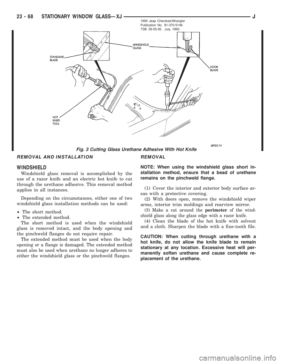
Windshield glass removal is accomplished by the
use of a razor knife and an electric hot knife to cut
through the urethane adhesive. This removal method
applies in all instances.
Depending on the circumstances, either one of two
windshield glass installation methods can be used:
²The short method.
²The extended method.
The short method is used when the windshield
glass is removed intact, and the body opening and
the pinchweld flanges do not require repair.
The extended method must be used when the body
opening or a flange is damaged. The extended method
must also be used when urethane no longer adheres to
either the windshield glass or the pinchweld flanges.
REMOVAL
NOTE: When using the windshield glass short in-
stallation method, ensure that a bead of urethane
remains on the pinchweld flange.
(1) Cover the interior and exterior body surface ar-
eas with a protective covering.
(2) With doors open, remove the windshield wiper
arms, interior trim moldings and rearview mirror.
(3) Make a cut around theperimeterof the wind-
shield glass along the glass edge with a razor knife.
(4) Clean the blade of the hot knife with solvent
and a cloth. Sharpen the blade with a fine-tooth file.
CAUTION: When cutting through urethane with a
hot knife, do not allow the knife blade to remain
stationary at any location. Excessive heat will per-
manently soften urethane and cause complete re-
placement of the urethane.
Fig. 3 Cutting Glass Urethane Adhesive With Hot Knife
23 - 68 STATIONARY WINDOW GLASSÐXJJ1995 Jeep Cherokee/Wrangler
Publication No. 81-370-5146
TSB 26-05-95 July, 1995
Page 1802 of 2198
(5) Start the hot knife blade (special tool C-4386)
between the glass and the urethane. Next, cut the
adhesive as close to the glass edge as possible (Fig.
1). Allow as much adhesive to remain on the pinch-
weld flange as possible.For best cutting results,
clean the knife blade frequently with steel wool
while the blade is hot.
(6) Remove the windshield glass from the body
opening.
(7) After the hot knife blade has cooled, clean the
blade with solvent and a clean cloth.
INSTALLATIONÐSHORT METHOD
Normally, after a replacement windshield glass is
installed, the rearview mirror bracket also requires
installation.Do not install the bracket until after
the windshield glass installation is completed.
(1) Inspect the windshield opening pinchweld
flanges. Prime any bare spots with urethane primer.
Allow a minimum of 18 minutes for dry time.
(2) Inspect urethane bead for high spots. Level
bead by shaving off high spots with a razor knife.
(3) Clean the outer edge of windshield glass with
naphtha or an equivalent product.
(4) Prime outer perimeter of interior side of glass 16
mm (5/8 inch) from edge. Use a wipe-off type urethane
primer and wipe glass dry after primer application.
NOTE: The reveal molding has an adhesive applied
to the windshield contact surface to help secure the
molding to the windshield during the installation
procedure.
(5) Apply the molding to the windshield:
²With the molding at room temperature, press the
molding onto the windshield corners.
²From corner to corner, work the molding to the
center of each side. (Some stretching of the mold-
ing may be required during this procedure.)(6) Place the glass on the pinchweld flanges and
inspect for gaps in the urethane. Gaps in excess of 3
mm (1/8 inch) must be filled with urethane.
(7) Adjust windshield glass position until it is
aligned with the flanges and adhesive. Next, make
alignment marks on the glass and body.
(8) Remove the windshield glass and position it on
a flat surface.
CAUTION: Avoid spilling or dripping primer on
painted surfaces. Clean spills or drips immediately.
The primer will damage the paint if it remains on
the surface for any length of time.
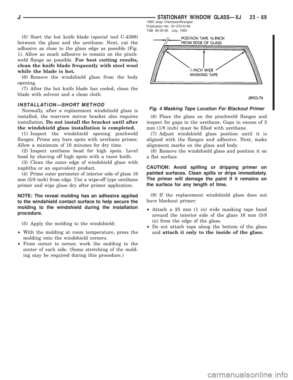
(9) If the replacement windshield glass does not
have blackout primer:
²Attach a 25 mm (1 in) wide masking tape band
around the interior side of the glass 16 mm (5/8
in) from the edge of the glass.
²Do not attach tape along the bottom of the glass
andattach it only to the inside of the glass.
Fig. 4 Masking Tape Location For Blackout Primer
JSTATIONARY WINDOW GLASSÐXJ 23 - 691995 Jeep Cherokee/Wrangler
Publication No. 81-370-5146
TSB 26-05-95 July, 1995
Page 1803 of 2198
²Clean the 16-mm (5/8-in) wide surface area around
the glass with isopropyl alcohol.
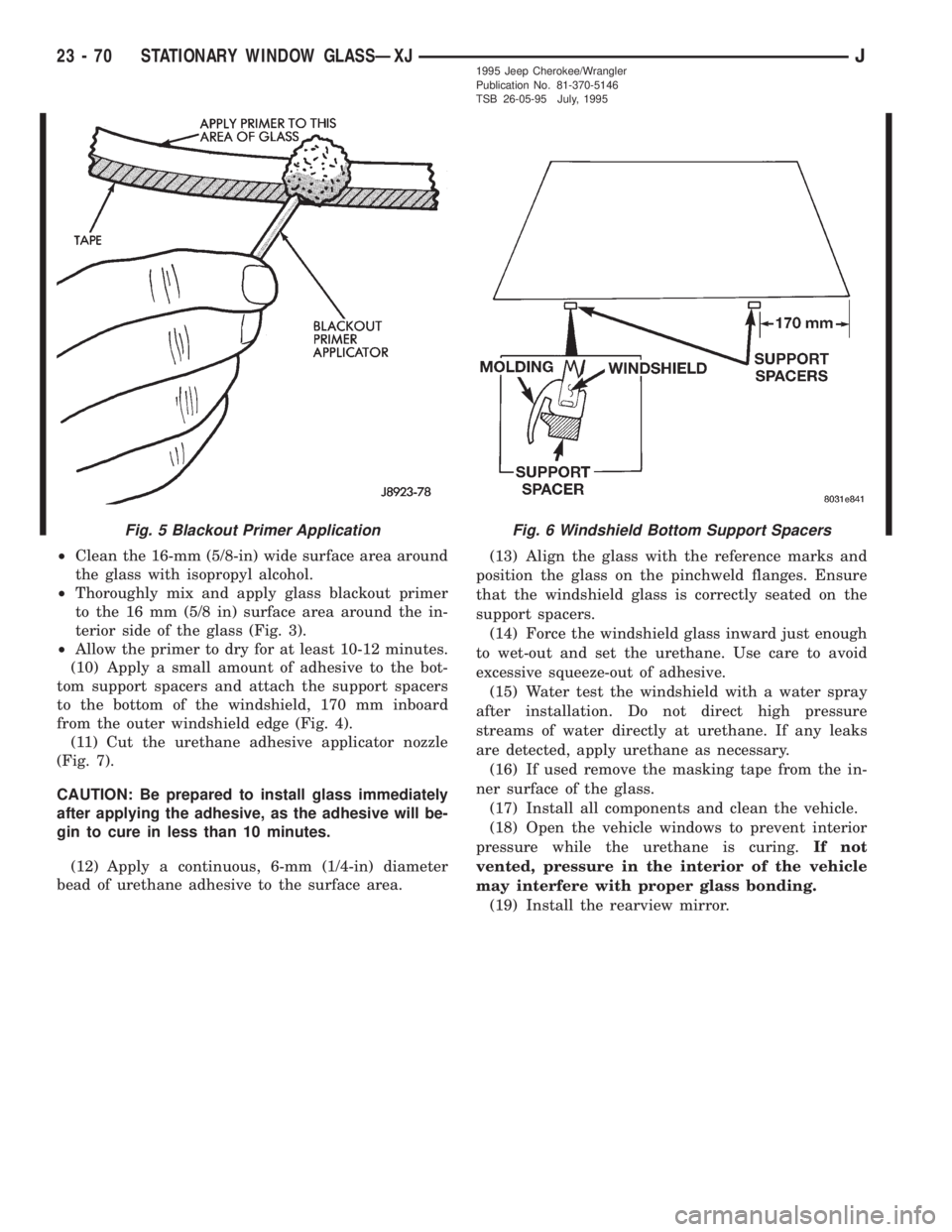
²Thoroughly mix and apply glass blackout primer
to the 16 mm (5/8 in) surface area around the in-
terior side of the glass (Fig. 3).
²Allow the primer to dry for at least 10-12 minutes.
(10) Apply a small amount of adhesive to the bot-
tom support spacers and attach the support spacers
to the bottom of the windshield, 170 mm inboard
from the outer windshield edge (Fig. 4).
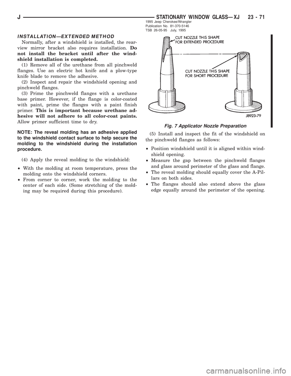
(11) Cut the urethane adhesive applicator nozzle
(Fig. 7).
CAUTION: Be prepared to install glass immediately
after applying the adhesive, as the adhesive will be-
gin to cure in less than 10 minutes.
(12) Apply a continuous, 6-mm (1/4-in) diameter
bead of urethane adhesive to the surface area.(13) Align the glass with the reference marks and
position the glass on the pinchweld flanges. Ensure
that the windshield glass is correctly seated on the
support spacers.
(14) Force the windshield glass inward just enough
to wet-out and set the urethane. Use care to avoid
excessive squeeze-out of adhesive.
(15) Water test the windshield with a water spray
after installation. Do not direct high pressure
streams of water directly at urethane. If any leaks
are detected, apply urethane as necessary.
(16) If used remove the masking tape from the in-
ner surface of the glass.
(17) Install all components and clean the vehicle.
(18) Open the vehicle windows to prevent interior
pressure while the urethane is curing.If not
vented, pressure in the interior of the vehicle
may interfere with proper glass bonding.
(19) Install the rearview mirror.
Fig. 6 Windshield Bottom Support SpacersFig. 5 Blackout Primer Application
23 - 70 STATIONARY WINDOW GLASSÐXJJ1995 Jeep Cherokee/Wrangler
Publication No. 81-370-5146
TSB 26-05-95 July, 1995
Page 1804 of 2198
INSTALLATIONÐEXTENDED METHOD
Normally, after a windshield is installed, the rear-
view mirror bracket also requires installation.Do
not install the bracket until after the wind-
shield installation is completed.
(1) Remove all of the urethane from all pinchweld
flanges. Use an electric hot knife and a plow-type
knife blade to remove the adhesive.
(2) Inspect and repair the windshield opening and
pinchweld flanges.
(3) Prime the pinchweld flanges with a urethane
base primer. However, if the flange is color-coated
with paint, prime the flanges with a paint finish
primer.This is important because urethane ad-
hesive will not adhere to all color-coat paints.
Allow primer sufficient time to dry.
NOTE: The reveal molding has an adhesive applied
to the windshield contact surface to help secure the
molding to the windshield during the installation
procedure.
(4) Apply the reveal molding to the windshield:
²With the molding at room temperature, press the
molding onto the windshield corners.
²From corner to corner, work the molding to the
center of each side. (Some stretching of the mold-
ing may be required during this procedure).(5) Install and inspect the fit of the windshield on
the pinchweld flanges as follows:
²Position windshield until it is aligned within wind-
shield opening.
²
Measure the gap between the pinchweld flanges
and glass around perimeter of the glass and flange.
²The reveal molding should equally cover the A-Pil-
lars on both sides.
²The flanges should also extend above the glass
edge equally around the perimeter of the opening.
Fig. 7 Applicator Nozzle Preparation
JSTATIONARY WINDOW GLASSÐXJ 23 - 711995 Jeep Cherokee/Wrangler
Publication No. 81-370-5146
TSB 26-05-95 July, 1995
Page 1805 of 2198
(6) If the pinchweld flanges require repair, remove
the windshield glass and straighten, align, or repair
the flange(s) as necessary.
(7) Position the windshield in the opening and in-
spect the windshield fit again. Mark the windshield
final position on the glass and body with a wax pen-
cil (or use masking tape). The marks (or masking
tape) will be used for installation alignment refer-
ence.
(8) If the replacement windshield does not have
blackout primer:
²Attach a 25-mm (1-in) wide masking tape band
around the interior side of glass 16 mm (5/8 in)
from edge of glass (Fig. 2).
²Do not attach tape along the bottom of the glass
and attach only to the inside of glass.
²Thoroughly mix and apply blackout primer to the
16 mm (5/8 in) surface area around the interior
side of the glass (Fig. 4).
²Allow the primer to dry for at least 10-12 minutes.
(9) Apply a small amount of adhesive to the bot-
tom support spacers and attach the support spacers
to the bottom of the windshield, 170 mm inboard
from the outer windshield edge (Fig. 6).
(10) Cut the urethane applicator nozzle (Fig. 7).
(11) Apply a continuous bead of urethane to the
surface area with blackout primer on the interior
side of glass. The bead should be 9-mm (3/8-in) wide
by 12.7-mm (1/2-in) deep for best results.CAUTION: Be prepared to install the windshield im-
mediately after applying the adhesive, as the adhe-
sive will begin to cure in less than 10 minutes.
(12) Align the windshield with the wax pencil in-
stallation alignment reference marks (or the tape
strips). Position the windshield on pinchweld flanges
and spacers.
(13) Force the windshield inward just enough to
wet-out and set the urethane. Use care to avoid ex-
cessive squeeze-out of adhesive.
(14) Water test the windshield with a water spray
after installation. Do not direct high pressure
streams of water directly at the urethane. If any
leaks are detected, apply urethane as necessary.
(15) If used, remove the masking tape from the in-
ner surface of glass.
(16) Install all components and clean the vehicle. If
necessary, refer to the installation procedures.
(17) Open the vehicle windows to prevent interior
pressure while the urethane adhesive is curing.If
not vented, pressure in the interior of vehicle
will interfere with glass bonding.
(18) Install the rearview mirror on the bracket.
REAR DOOR STATIONARY WINDOW GLASS
REMOVAL
(1) Lower the window glass.
(2) Pry the window beltline molding away from the
clips and remove the molding from the door.
(3) Remove the window weatherstrip seals from
the door.
23 - 72 STATIONARY WINDOW GLASSÐXJJ1995 Jeep Cherokee/Wrangler
Publication No. 81-370-5146
TSB 26-05-95 July, 1995
Page 1806 of 2198
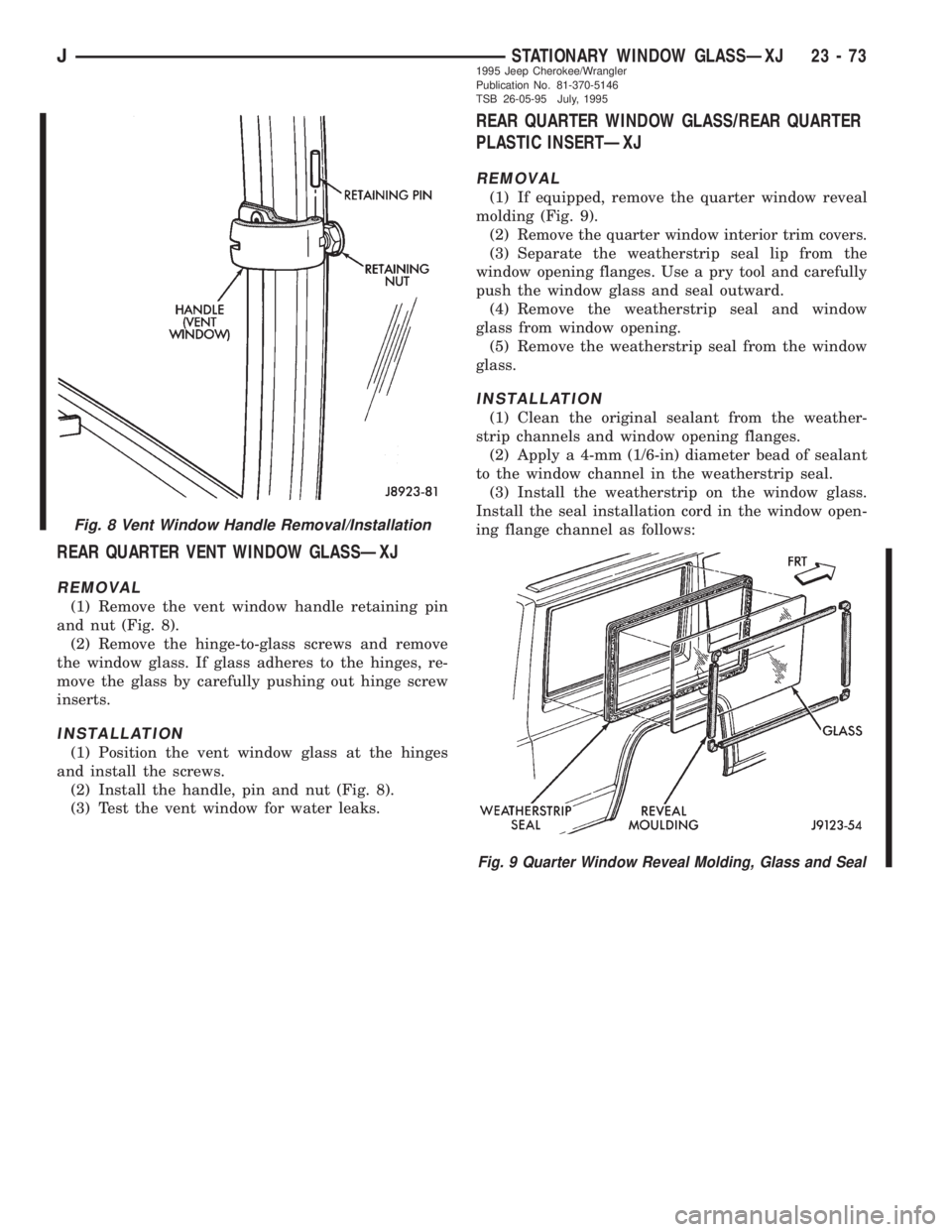
REAR QUARTER VENT WINDOW GLASSÐXJ
REMOVAL
(1) Remove the vent window handle retaining pin
and nut (Fig. 8).
(2) Remove the hinge-to-glass screws and remove
the window glass. If glass adheres to the hinges, re-
move the glass by carefully pushing out hinge screw
inserts.
INSTALLATION
(1) Position the vent window glass at the hinges
and install the screws.
(2) Install the handle, pin and nut (Fig. 8).
(3) Test the vent window for water leaks.
REAR QUARTER WINDOW GLASS/REAR QUARTER
PLASTIC INSERTÐXJ
REMOVAL
(1) If equipped, remove the quarter window reveal
molding (Fig. 9).
(2)
Remove the quarter window interior trim covers.
(3) Separate the weatherstrip seal lip from the
window opening flanges. Use a pry tool and carefully
push the window glass and seal outward.
(4) Remove the weatherstrip seal and window
glass from window opening.
(5) Remove the weatherstrip seal from the window
glass.
INSTALLATION
(1) Clean the original sealant from the weather-
strip channels and window opening flanges.
(2) Apply a 4-mm (1/6-in) diameter bead of sealant
to the window channel in the weatherstrip seal.
(3) Install the weatherstrip on the window glass.
Install the seal installation cord in the window open-
ing flange channel as follows:
Fig. 8 Vent Window Handle Removal/Installation
Fig. 9 Quarter Window Reveal Molding, Glass and Seal
JSTATIONARY WINDOW GLASSÐXJ 23 - 731995 Jeep Cherokee/Wrangler
Publication No. 81-370-5146
TSB 26-05-95 July, 1995
Page 1807 of 2198
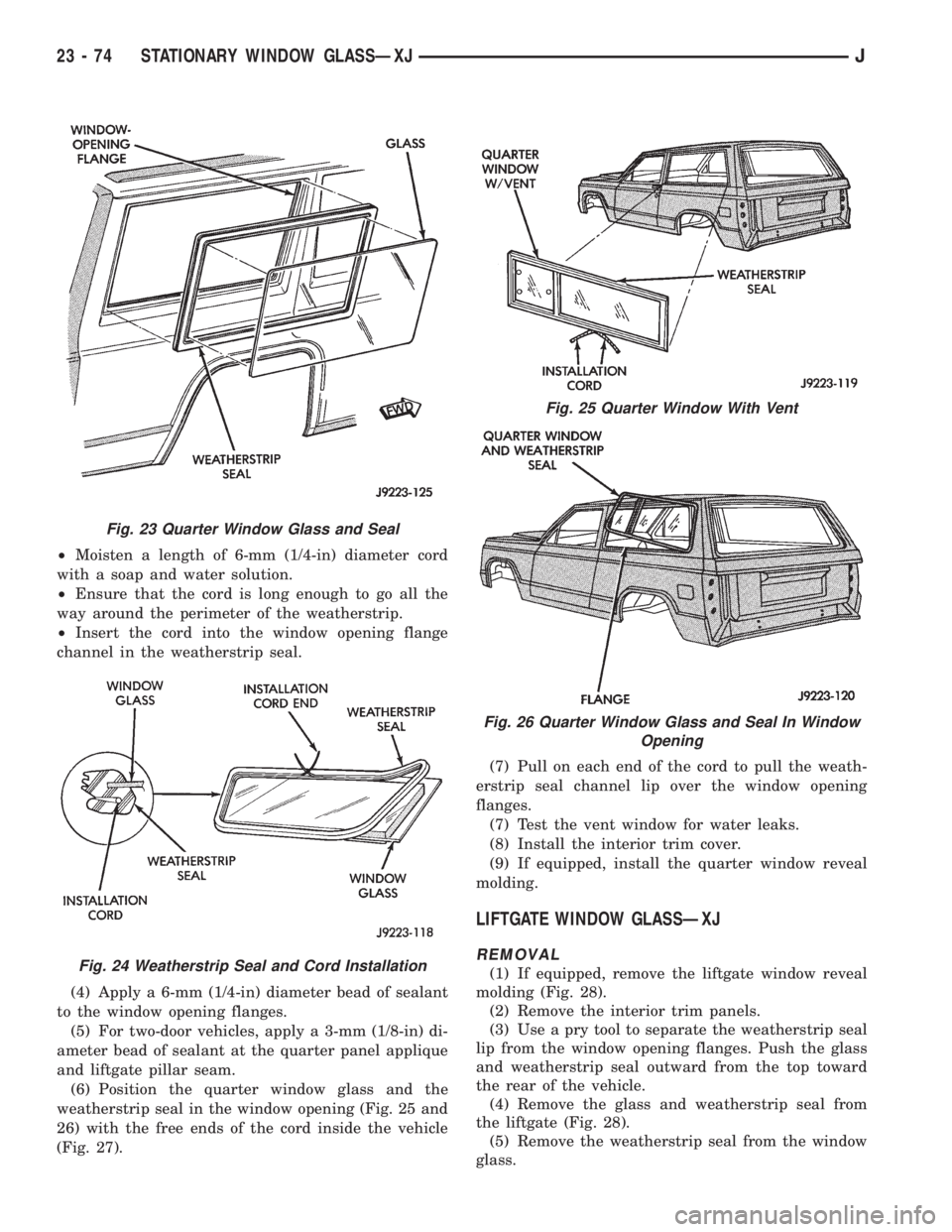
²Moisten a length of 6-mm (1/4-in) diameter cord
with a soap and water solution.
²Ensure that the cord is long enough to go all the
way around the perimeter of the weatherstrip.
²Insert the cord into the window opening flange
channel in the weatherstrip seal.
(4) Apply a 6-mm (1/4-in) diameter bead of sealant
to the window opening flanges.
(5) For two-door vehicles, apply a 3-mm (1/8-in) di-
ameter bead of sealant at the quarter panel applique
and liftgate pillar seam.
(6) Position the quarter window glass and the
weatherstrip seal in the window opening (Fig. 25 and
26) with the free ends of the cord inside the vehicle
(Fig. 27).(7) Pull on each end of the cord to pull the weath-
erstrip seal channel lip over the window opening
flanges.
(7) Test the vent window for water leaks.
(8) Install the interior trim cover.
(9) If equipped, install the quarter window reveal
molding.
LIFTGATE WINDOW GLASSÐXJ
REMOVAL
(1) If equipped, remove the liftgate window reveal
molding (Fig. 28).
(2) Remove the interior trim panels.
(3) Use a pry tool to separate the weatherstrip seal
lip from the window opening flanges. Push the glass
and weatherstrip seal outward from the top toward
the rear of the vehicle.
(4) Remove the glass and weatherstrip seal from
the liftgate (Fig. 28).
(5) Remove the weatherstrip seal from the window
glass.
Fig. 23 Quarter Window Glass and Seal
Fig. 24 Weatherstrip Seal and Cord Installation
Fig. 25 Quarter Window With Vent
Fig. 26 Quarter Window Glass and Seal In Window
Opening
23 - 74 STATIONARY WINDOW GLASSÐXJJ
Page 1808 of 2198
(6) Clean the weatherstrip channels and window
opening flanges.
INSTALLATION
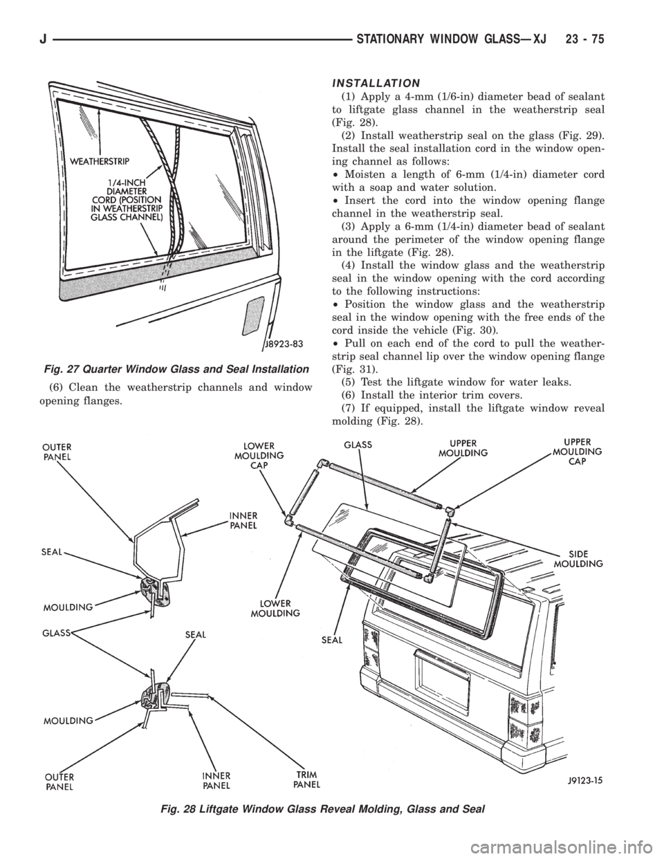
(1) Apply a 4-mm (1/6-in) diameter bead of sealant
to liftgate glass channel in the weatherstrip seal
(Fig. 28).
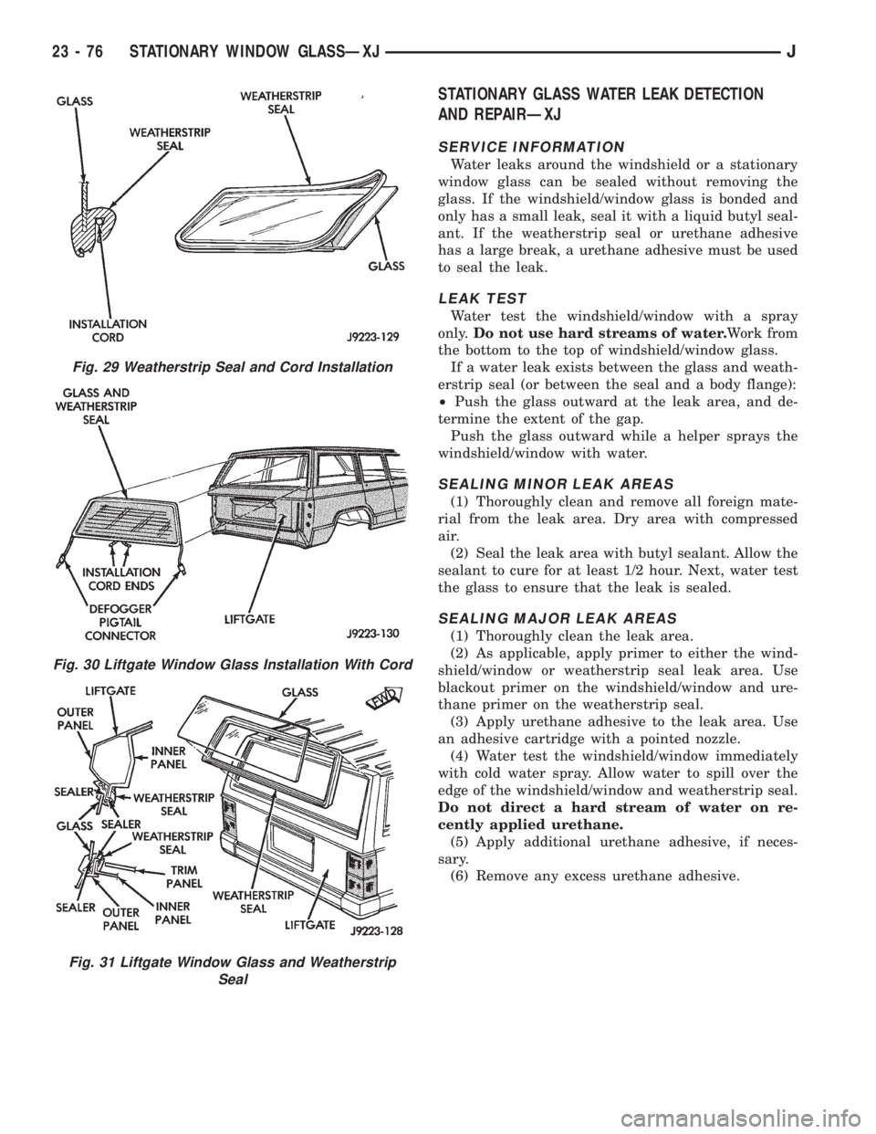
(2) Install weatherstrip seal on the glass (Fig. 29).
Install the seal installation cord in the window open-
ing channel as follows:
²Moisten a length of 6-mm (1/4-in) diameter cord
with a soap and water solution.
²Insert the cord into the window opening flange
channel in the weatherstrip seal.
(3) Apply a 6-mm (1/4-in) diameter bead of sealant
around the perimeter of the window opening flange
in the liftgate (Fig. 28).
(4) Install the window glass and the weatherstrip
seal in the window opening with the cord according
to the following instructions:
²Position the window glass and the weatherstrip
seal in the window opening with the free ends of the
cord inside the vehicle (Fig. 30).
²Pull on each end of the cord to pull the weather-
strip seal channel lip over the window opening flange
(Fig. 31).
(5) Test the liftgate window for water leaks.
(6) Install the interior trim covers.
(7) If equipped, install the liftgate window reveal
molding (Fig. 28).
Fig. 28 Liftgate Window Glass Reveal Molding, Glass and Seal
Fig. 27 Quarter Window Glass and Seal Installation
JSTATIONARY WINDOW GLASSÐXJ 23 - 75
Page 1809 of 2198
STATIONARY GLASS WATER LEAK DETECTION
AND REPAIRÐXJ
SERVICE INFORMATION
Water leaks around the windshield or a stationary
window glass can be sealed without removing the
glass. If the windshield/window glass is bonded and
only has a small leak, seal it with a liquid butyl seal-
ant. If the weatherstrip seal or urethane adhesive
has a large break, a urethane adhesive must be used
to seal the leak.
LEAK TEST
Water test the windshield/window with a spray
only.Do not use hard streams of water.Work from
the bottom to the top of windshield/window glass.
If a water leak exists between the glass and weath-
erstrip seal (or between the seal and a body flange):
²Push the glass outward at the leak area, and de-
termine the extent of the gap.
Push the glass outward while a helper sprays the
windshield/window with water.
SEALING MINOR LEAK AREAS
(1) Thoroughly clean and remove all foreign mate-
rial from the leak area. Dry area with compressed
air.
(2) Seal the leak area with butyl sealant. Allow the
sealant to cure for at least 1/2 hour. Next, water test
the glass to ensure that the leak is sealed.
SEALING MAJOR LEAK AREAS
(1) Thoroughly clean the leak area.
(2) As applicable, apply primer to either the wind-
shield/window or weatherstrip seal leak area. Use
blackout primer on the windshield/window and ure-
thane primer on the weatherstrip seal.
(3) Apply urethane adhesive to the leak area. Use
an adhesive cartridge with a pointed nozzle.
(4) Water test the windshield/window immediately
with cold water spray. Allow water to spill over the
edge of the windshield/window and weatherstrip seal.
Do not direct a hard stream of water on re-
cently applied urethane.
(5) Apply additional urethane adhesive, if neces-
sary.
(6) Remove any excess urethane adhesive.
Fig. 29 Weatherstrip Seal and Cord Installation
Fig. 30 Liftgate Window Glass Installation With Cord
Fig. 31 Liftgate Window Glass and Weatherstrip
Seal
23 - 76 STATIONARY WINDOW GLASSÐXJJ
Page 1810 of 2198
TRAILER HITCH
TRAILER HITCHÐXJ
CLASS III HITCH
A class III weight-distributing/equalizer type hitch
can be used to tow a trailer:
²Having a maximum gross weight of 5,000 lbs/2250
kg.
²Having a maximum tongue weight of 750 lbs/332
kg).
The following vehicle basic equipment is required
for class III trailer towing:
²P205/75R15 or larger tires.
²Full size spare tire.
²Trailer sway control.
²Trailer tow wire harness and connector.
²Heavy duty turn signal flasher element.
²Heavy duty axle (with synthetic lubricant).
²Heavy duty cooling system.
²Heavy duty generator/battery.
²Auxiliary automatic transmission fluid cooler.
²I-6, 4.0L engine.
Wide-angle type door mirrors are recommended but
not required.
WIRE HARNESS CONNECTORS
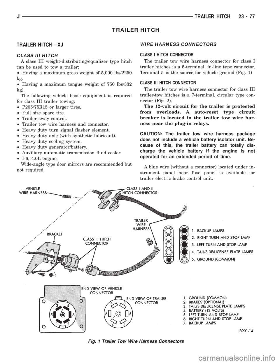
CLASS I HITCH CONNECTOR
The trailer tow wire harness connector for class I
trailer hitches is a 5-terminal, in-line type connector.
Terminal 5 is the source for vehicle ground (Fig. 1)
CLASS III HITCH CONNECTOR
The trailer tow wire harness connector for class III
trailer-tow hitches is a 7-terminal, circular type con-
nector (Fig. 2).
The 12-volt circuit for the trailer is protected
from overloads. A auto-reset type circuit
breaker is located in the trailer tow wire har-
ness near the plug-in relays.
CAUTION: The trailer tow wire harness package
does not include a vehicle battery isolator unit. Be-
cause of this, the trailer battery can totally dis-
charge the vehicle battery if the engine is not
operated for an extended period of time.
A blue wire (without a connector) located under in-
strument panel near fuse panel is available for
trailer electric brake control unit.
Fig. 1 Trailer Tow Wire Harness Connectors
JTRAILER HITCH 23 - 77