JEEP CJ 1953 Service Manual
Manufacturer: JEEP, Model Year: 1953, Model line: CJ, Model: JEEP CJ 1953Pages: 376, PDF Size: 19.96 MB
Page 331 of 376
'Jeep*
UNIVERSAL SERIES SERVICE
MANUAL
P
f. On vehicles without a transmission brake hold
the brake
shoes
in their relative position and
engage
the parking brake cable
into
the parking
brake
lever.
g. On vehicles without a transmission brake in
stall
the parking brake strut and spring
between
the parking brake lever and the primary
shoe.
h.
Place the brake
shoes
on the backing plate and
install
the retainer pins, springs and retainers.
i.
Install the anchor pin plate.
j.
Install the lever and
sleeve
on the primary
shoe
then install the secondary return spring, then the
primary
return spring.
Important:
A
"L"
or "R" is located on the hex
agon
side of the lever crank for identification. The
lever crank marked "R" applies to the primary
shoe
on the
left
rear brake assembly. The lever
crank
marked
"L"
applies to the primary
shoe
on
the right rear brake assembly.
k. Place the upper linkage rod in the
groove
of the
anchor pin and
engage
the hook of the link rod
into
the adjusting lever.
I.
Install the brake drum. Install the wheel and
tire
assembly.
m. Adjust the brakes as described
below.
P-19.
Brake
Shoe
Initial
Adjustment —
a.
Should wheel brake units have
been
disassem bled for any reason, an initial adjustment
MUST
be made
before
drum installation.
b.
When the brake parts have
been
installed in
their correct position, initially adjust the adjusting
screw assemblies to a point where approximately Y% [9,53 mm.] of threads are
exposed
between
the
star
wheel and star wheel nut.
Note:
Following the initial adjustment and final
assembly, check brake pedal height to ensure
brake
operation. Then drive the car in reverse and
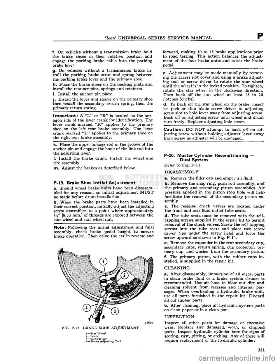
FIG.
P-12—BRAKE SHOE ADJUSTMENT
1—
Star
Wheel
2—
Lever
3—
Screwdriver
4—
Brake
Adjusting Tool
forward,
making 10 to 15 brake applications prior
to road testing.
This
action balances the adjust
ment of the four brake units and raises the brake
pedal.
c. Adjustment may be made manually by removing the access
slot
cover and using a brake adjust
ing
tool
or screw driver to rotate the star wheel
until
the wheel is in the locked position. To tighten, rotate the star wheel in the clockwise direction.
Then
back off the star wheel at least 15 to 20
notches
(clicks).
d.
To back off the star wheel on the brake, insert
ice pick or thin blade screw driver in adjusting screw
slot
to hold lever away from adjusting screw.
Back
off on adjusting screw until wheel and drum
turn
freely. Replace adjusting
hole
cover.
Caution:
DO NOT attempt to back off on ad
justing screw without holding adjuster lever away from screw as adjuster
will
be damaged.
P-20. Master Cylinder Reconditioning —
Dual
System
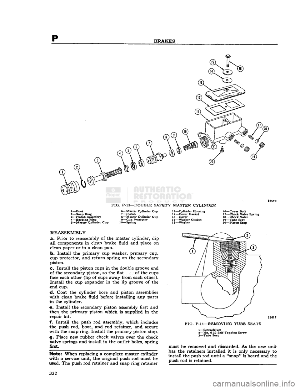
Refer
to Fig. P-13.
DISASSEMBLY
a.
Remove the filler cap and empty all fluid.
b.
Remove the snap ring, push rod assembly, and
the primary and secondary piston assemblies. Air pressure applied in the piston
stop
hole
will
help
facilitate the removal of the secondary piston as
sembly.
c. The residual check valves are located under
the front and rear fluid
outlet
tube
seats.
d.
The
tube
seats
must be removed with the
self-
tapping screws supplied in the repair kit to permit removal of the check valves. Screw the self-tapping
screws
into
the
tube
seats
and place two screw
driver
tips under the screw head and force the
screw upward as shown in Fig. P-14.
e. Remove the expander in the rear secondary cup, secondary cups, return spring, cup protector,
pri
mary
cup, and washer from the secondary piston.
f. The primary piston, with the rubber cups in stalled, is supplied in the repair kit.
CLEANING
a.
After disassembly, immersion of all metal parts
in
clean brake fluid or a brake system cleaner is
recommended. Use air
hose
to blow out dirt and cleaning solvent from recesses and internal pas
sages.
When overhauling a hydraulic brake unit,
use all parts furnished in the repair kit. Discard
all
old rubber parts.
b.
After cleaning, place
all"
hydraulic
system parts
on clean paper or in a clean pan.
INSPECTION
Inspect all other parts for damage or
excessive
wear.
Replace any damaged, worn, or chipped
parts.
Inspect hydraulic cylinder bore for
signs
of
scoring, rust, pitting, or etching. Any of
these
will
require
replacement of the hydraulic cylinder. 331
Page 332 of 376
BRAKES
12519
FIG.
P-13—DOUBLE
SAFETY MASTER CYLINDER
1— Boot
2— Snap Ming 3"*—Piston Assembly
4—
Backing
Ring 5—
Master
Cylinder Cup 6—
Master
Cylinder Cup
7— Piston
8—
Master
Cylinder Cup 9—
Cup
Protector
10—Spring 11—
Cylinder
Housing
12—
Cover
Gasket
13—
Cover
14—
Washer
Gasket 15—
Washer
16—
Cover
Bolt
17—
Check
Valve Spring 18—
Check
Valve
19—
Tube
Seat
20— Piston Stop
REASSEMBLY
a.
Prior
to reassembly of the master cylinder, dip
all
components
in clean brake fluid and place on
clean paper or in a clean pan.
b.
Install the primary cup washer, primary cup,
cup protector, and return spring on the secondary piston.
c. Install the piston cups in the double
groove
end
of the secondary piston, so the flat j of the cups face each other (lip of cups away from each other).
Install
the cup expander in the lip
groove
of the
end cup.
cL
Coat the cylinder bore and piston assemblies with clean brake fluid
before
installing any parts
in
the cylinder.
e. Install the secondary piston assembly first and then the primary piston which is supplied in the
repair
kit.
f.
Install the push rod assembly, which includes
the push rod,
boot,
and rod retainer, and secure
with the snap ring. Install the primary piston
stop.
g. Place new rubber check valves over the check valve springs and install in the
outlet
holes, spring
first.
Note:
When replacing a
complete
master cylinder
with a service unit, the original push rod must be used. The push rod retainer and snap ring retainer 12617
FIG.
P-14—REMOVING TUBE SEATS 1
—Screwdriver
2— No. 6-32 Self-Tapping Screw
3—
Tube
Seat must be removed and discarded. As the new unit
has the retainers installed it is only necessary to
install
the push rod until a "snap" is heard and the push rod is retained. 332
Page 333 of 376
'Jeep'
UNIVERSAL
SERIES SERVICE
MANUAL
P h.
Install
the tube seats, flat side toward the check
valve,
and press in with tube nuts or the master
cylinder
brake pipe tube nuts.
BLEEDING
a.
Before the master cylinder is installed on the
car,
the unit must be bled.
b.
Support the cylinder assembly in a vise and
fill
both fluid reservoirs with approved brake fluid,
e.
Loosely install a plug in each
outlet
of the
cylinder.
Depress the push rod several times until
air
bubbles cease to appear in the brake fluid.
d.
Tighten the plugs and attempt to depress the piston. The piston travel should be restricted after
all
air is expelled.
e.
Install
the master cylinder on the car and bleed
the hydraulic lines at the wheel cylinder. Refer to
Par.
P-7.
P-21.
Wheel
Cylinder
Reconditioning
•
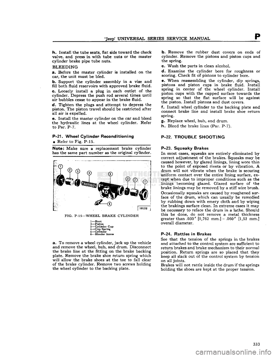
Refer to Fig. P-15.
Note:
Make sure a replacement brake cylinder
has the same part number as the original cylinder.
FIG.
P-15—WHEEL
BRAKE CYLINDER
1— Boot
2—
Piston
3—
Cylinder
Cup
4—
Cup
Spring
5—
Cylinder
6—
Bleeder
Screw
a.
To remove a wheel cylinder,
jack
up the vehicle
and
remove the wheel, hub, and
drum.
Disconnect
the brake line at the fitting on the brake backing
plate. Remove the brake
shoe
return spring which
will
allow the brake
shoes
at the toe to
fall
clear of the brake cylinder. Remove two screws holding
the wheel cylinder to the backing plate.
b.
Remove the rubber dust covers on ends of
cylinder.
Remove the pistons and piston cups and
the spring.
c.
Wash the parts in clean alcohol.
d.
Examine the cylinder bore for roughness or
scoring.
Check
fit of pistons to cylinder bore.
e. When reassembling the cylinder, dip springs, pistons and piston cups in brake fluid.
Install
spring
in center of the wheel cylinder.
Install
piston cups with the cupped surface towards the
spring
so that the flat surface
will
be against
the piston.
Install
pistons and dust covers.
f.
Install
wheel cylinder to the backing plate and connect brake line and install brake
shoe
return
spring.
g. Replace wheel, hub, and
drum.
h.
Bleed the brake lines (Par. P-7).
P-22. TROUBLE
SHOOTING
P-23.
Squeaky
Brakes
In
most cases, squeaks are entirely eliminated by
correct
adjustment of the brakes. Squeaks may be
caused however, by glazed linings, lining wore thin
to the point of
exposed
rivets or by vibration. A
drum
will
not vibrate when the brake is securing
uniform
contact over the entire lining surface, ex
cept when due to improper conditions such as the
linings becoming glazed.
Glazed
surface of the
brake
linings may be removed by a stiff
wire
brush.
Occasionally
squeaks are caused by roughened
sur
face of the
drum,
which can usually be remedied
by rubbing down with emery cloth and by wiping
the brakings surface clean. In extreme cases it may
be necessary to reface the drum in a lathe. Should
this be done, do not remove a metal thickness greater than .030" [0,762 mm.] - .060" [1,52 mm.]
overall
diameter.
P-24. Rattles
in
Brakes
See that the tension of the springs in the brakes
and
attached to the control system are sufficient to
return
brakes and brake mechanism to their normal
position.
Return
springs are so placed that they
keep all slack out of the control system by tension on all joints.
Brakes
will
not rattle inside the
drum
if the springs
holding the
shoes
are kept at the proper tension. 333
Page 334 of 376
p
BRAKES
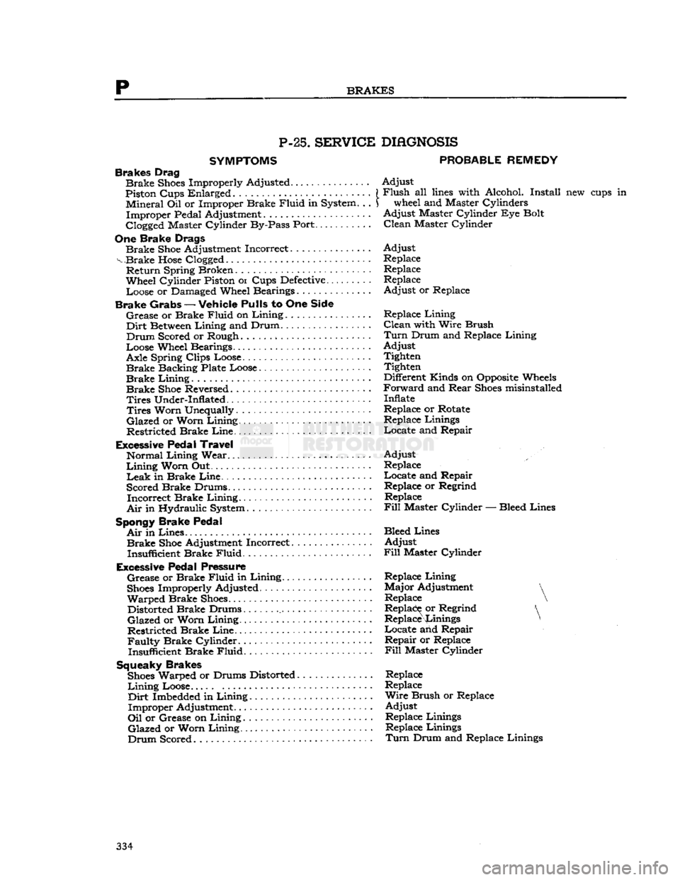
P-25.
SERVICE
SYMPTOMS
Brakes Drag
Brake
Shoes
Improperly Adjusted
Piston Cups Enlarged . . •.
«•
Mineral
Oil or Improper Brake
Fluid
in System. . .
Improper
Pedal Adjustment
Clogged Master Cylinder By-Pass Port...
One
Brake Drags
Brake
Shoe
Adjustment Incorrect
v Brake
Hose
Clogged.
Return
Spring Broken
Wheel Cylinder Piston
01
Cups
Defective.........
Loose or Damaged Wheel Bearings
Brake Grabs
—
Vehicle Pulls
to One
Side
Grease
or Brake
Fluid
on
Lining................
Dirt
Between
Lining
and Drum
Drum
Scored or Rough
Loose Wheel Bearings. .
Axle Spring Clips Loose
Brake
Backing Plate Loose
Brake
Lining
..
Brake
Shoe
Reversed
Tires
Under-Inflated -
Tires
Worn Unequally
Glazed
or Worn
Lining
Restricted Brake
Line
Excessive Pedal Travel
Normal
Lining
Wear
Lining
Worn Out ... .
Leak
in Brake
Line.
Scored Brake Drums
Incorrect
Brake
Lining.
Air
in Hydraulic System
Spongy Brake Pedal
Air
in
Lines.
Brake
Shoe
Adjustment Incorrect
Insufficient Brake
Fluid
Excessive Pedal Pressure
Grease
or Brake
Fluid
in
Lining
Shoes
Improperly Adjusted
Warped
Brake
Shoes
Distorted Brake Drums
Glazed
or Worn
Lining
Restricted Brake
Line
Faulty
Brake Cylinder Insufficient Brake
Fluid.
Squeaky Brakes
Shoes
Warped or Drums Distorted
Lining
Loose.....
Dirt
Imbedded in
Lining
Improper
Adjustment.
Oil
or Grease on
Lining
Glazed
or Worn
Lining.
Drum
Scored
DIAGNOSIS
PROBABLE
REMEDY
Adjust
Flush
all
lines
with Alcohol. Install new cups in wheel and Master Cylinders
Adjust
Master Cylinder Eye Bolt
Clean
Master Cylinder
Adjust
Replace Replace
Replace
Adjust
or Replace
Replace
Lining
Clean
with Wire Brush
Turn
Drum and Replace
Lining
Adjust
Tighten Tighten
Different Kinds on Opposite Wheels
Forward
and
Rear
Shoes
misinstalled
Inflate
Replace or Rotate Replace Linings
Locate
and Repair
Adjust
Replace
Locate
and Repair Replace or Regrind Replace
Fill
Master
Cylinder
— Bleed Lines
Bleed Lines
Adjust
Fill
Master Cylinder
Replace
Lining
Major
Adjustment
Replace
Replace or Regrind Replace Linings * .
Locate
and Repair
Repair
or Replace
Fill
Master Cylinder Replace
Replace
Wire
Brush or Replace
Adjust
Replace Linings Replace Linings
Turn
Drum and Replace Linings 334
Page 335 of 376
'Jeep'
UNIVERSAL
SERIES SERVICE
MANUAL
WHEELS
Contents
SUBJECT PAR.
GENERAL
Q-l Wheel Balancing. Q-2
WHEEL BEARING SERVICE.
......
Q-3
Checking
Front Wheel Bearings Q-4
Checking
Rear Wheel Bearings.
.......
.
Q-7
Front
Wheel Bearing Adjustment. Q-5
Rear
Wheel Bearing Adjustment — Flanged Axle Q-6
Rear
Wheel Bearing Adjustment —
Tapered
Axle Q-8 SUBJECT PAR.
REAR WHEEL
MOUNTING
.Q-9
BRAKE
DRUM
SERVICE.
......
. . .Q-10
TIRE
SERVICE.
.................
.Q-ll
Tire
Care
Q-l2
Tire
Removal and Installation. Q-l3
SPECIFICATIONS
. .Q-14
Q-l.
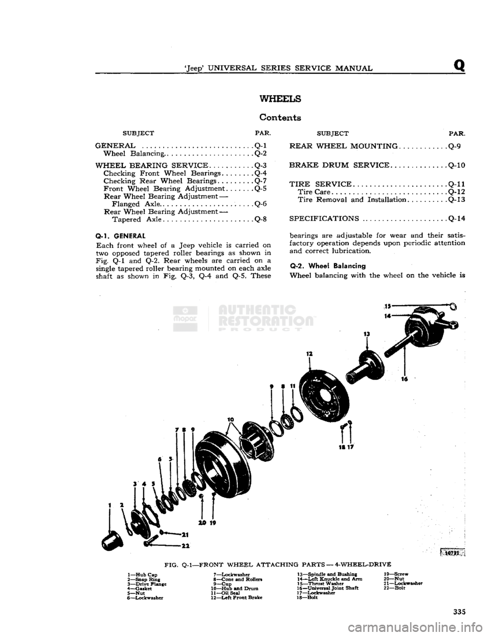
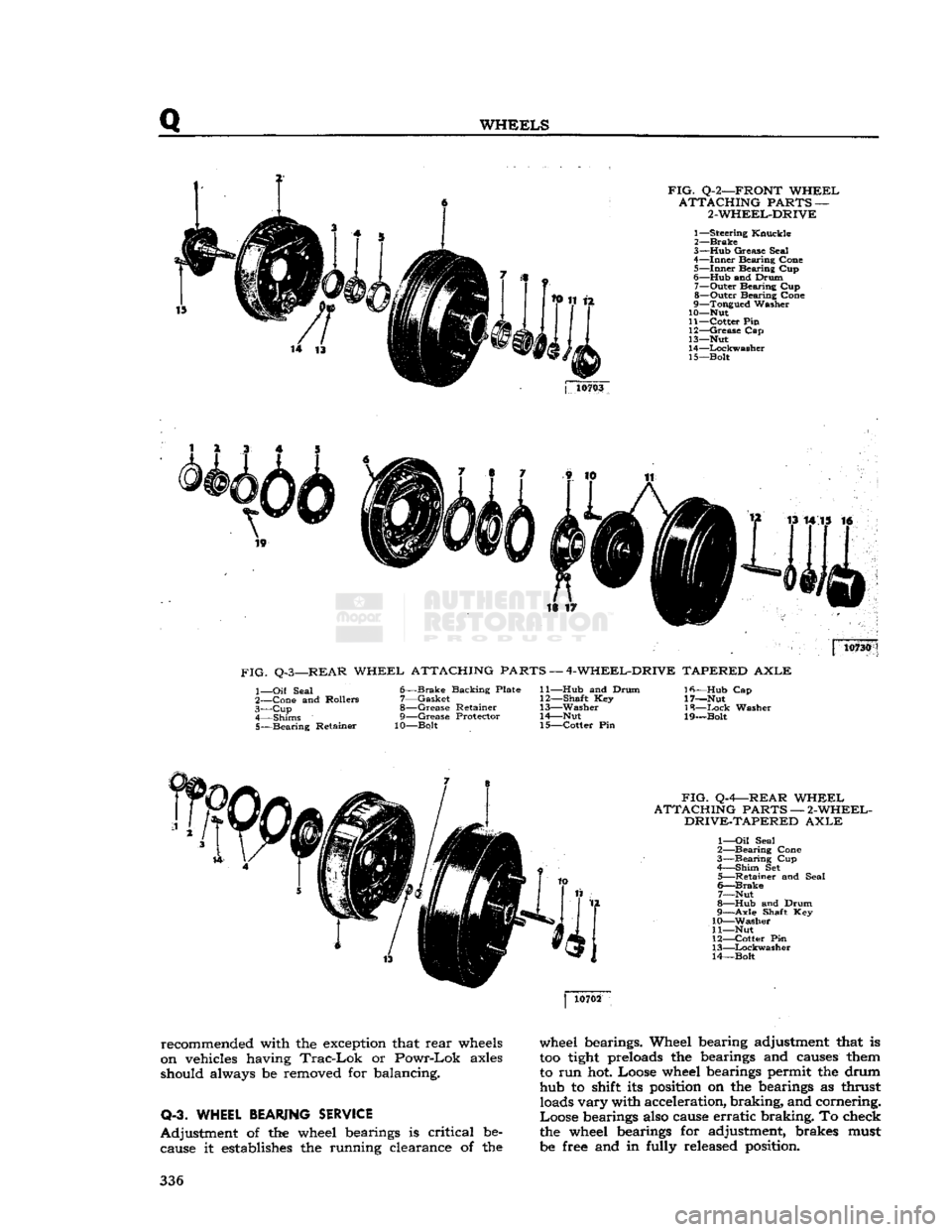
GENERAL
Each
front wheel of a Jeep vehicle is carried on
two
opposed
tapered roller bearings as shown in
Fig.
Q-l and Q-2. Rear
wheels
are carried on a
single
tapered roller bearing
mounted
on each axle
shaft as shown in Fig. Q-3, Q-4 and Q-5. These bearings are adjustable for wear and their satis
factory operation
depends
upon periodic
attention
and correct lubrication.
Q-2.
Wheel Balancing
Wheel balancing with the wheel on the vehicle is 18 17
10731
FIG.
Q-l—FRONT
WHEEL ATTACHING PARTS — 4-WHEEL-DRIVE 1— Hub Cap
2— Snap Ring
3—
Drive
Flange
4— Gasket 5— Nut
6—
Lockwasher
7—
Lockwasher
8— Cone and Rollers 9—
Cup
10— Hub and Drum 11—
Oil
Seal
12—
Left
Front Brake 13— Spindle and Bushing
14—
Left
Knuckle and Arm
15—
Thrust
Washer
16—
Universal
Joint Shaft
17—
Lockwasher
18—Bolt 19— Screw
20— Nut
21—
Lockwasher
22— Bolt 335
Page 336 of 376
Q
WHEELS
FIG.
Q-2—FRONT
WHEEL
ATTACHING
PARTS —
2-WHEEL-DRIVE
1—
Steering
Knuckle
2—
Brake
3— Hub
Grease
Seal
4—
Inner
Bearing
Cone
5—
Inner
Bearing
Cup
6—
Hub
and
Drum
7—
Outer
Bearing
Cup
8—
Outer
Bearing
Cone
9—
Tongued
Washer
10— Nut
11—
Cotter
Pin
12—
Grease
Cap
13— Nut
14—
Lockwasher
15—
Bolt
j
10703
is ir 10730
FIG.
Q-3—REAR
WHEEL
ATTACHING PARTS —
4-WHEEL-DRIVE
TAPERED
AXLE
1—
Oil
Seal
2—
Cone
and
Rollers
3— Cup
4—
Shims
5—
Bearing
Retainer
6—
Brake
Backing
Plate
7—
Gasket
8—
Grease
Retainer
9—
Grease
Protector
10—Bolt
11— Hub
and
Drum
12—
Shaft
Key
13—
Washer
14—
Nut
15—
Cotter
Pin
Ifi—Hub
Cap
17—Nut
18—
Ixick
Washer
19—Bolt
FIG.
Q-4—REAR
WHEEL
ATTACHING
PARTS —
2-WHEEL-
DRIVE-TAPERED
AXLE
1—
Oil
Seal
2—
Bearing
Cone
3—
Bearing
Cup
4—
Shim
Set
5—
Retainer
and
Seal
6—
Brake
7—
Nut
8—
Hub
and
Drum
9—
Axle
Shaft Key
10—
Washer
11— Nut
12—
Cotter
Pin
13—
Lockwasher
14—
Bolt
recommended with the exception that
rear
wheels
on vehicles having
Trac-Lok
or
Powr-Lok
axles
should always be removed for balancing.
Q-3. WHEEL
BEARING
SERVICE
Adjustment
of the wheel bearings is
critical
be cause it establishes the running clearance of the wheel bearings. Wheel bearing adjustment that is
too
tight
preloads the bearings and causes them
to run hot. Loose wheel bearings permit the drum hub to shift its position on the bearings as thrust loads
vary
with acceleration,
braking,
and cornering.
Loose
bearings also cause
erratic
braking.
To check
the wheel bearings for adjustment, brakes must
be free and in fully released position. 336
Page 337 of 376
'Jeep'
UNIVERSAL
SERIES SERVICE
MANUAL
FIG.
Q-5—REAR
WHEEL
ATTACHING
PARTS —
FLANGED
AXLE
1—
Brake
Backing Plate
2—
Retainer
Ring
3—
Unit-Bearing
4—
Oil
Seal
5—
Retainer
Plate 6—
Brake
Drum
7—
Cup
Plug
8—
Flanged
Axle Shaft
14284
Q-4. Checking
Front
Wheel Bearings
Raise
the front end of the vehicle with a
jack
so that the tires clear the floor.
Grip
the tire and
test
sidewise shake of the wheel.
If
bearings are correctly adjusted, shake of the
wheel
will
be just perceptible and wheel
will
turn
freely with no drag.
If
bearing adjustment is too tight, the rollers may
break
or
become
overheated. Loose bearings may cause
excessive
wear and noise.
If
this
test
indicates bearing adjustment is neces
sary,
follow
the procedure given in Par. Q-5. Loose
bearings
will
cause sidewise shake that is evident
around
the entire circumference of the wheel. A shake that is evident only when gripping the
wheels
in
a plane parallel to the ground, but not evident
around
the entire circumference, probably indicates
looseness
in the steering linkage.
Q-5.
Front Wheel Bearing Adjustment
With
the vehicle on the
jack,
the following proce
dure
should be followed to adjust the front wheel
bearings on four wheel-drive vehicles.
a. Remove the hub cap, snap
ring,
capscrews, and
washers that attach the driving
flange
to the hub.
b.
Using the
Front
Axle Shaft Drive Flange Puller
W-163,
pull
the driving flange.
c. Bend the lip of the nut lock washer so that the
locknut
and lock washer may be removed.
d.
Rotate the wheel and tighten the adjustment nut until the wheel binds.
Note:
Front
tire and wheel must be rotated by
hand
as the adjusting nut is
tightened
to ensure positive seating of the bearing.
Then
back off the adjusting nut about one-sixth
turn
making sure that wheel rotates freely without
sidewise shake.
e. Replace the lock washers and locknut. Bend
over the lock washer lip.
f.
Check
the adjustment (Par. Q-4). Reassemble the driving
flange
and hub cap. Make certain the
gasket is properly installed
between
the hub and
the flange.
•
Model DJ-5, DJ-6
On
two-wheel drive vehicles, remove the hub cap
and
the wheel retaining nut cotter pin. Rotate the
wheel and tighten the wheel retaining nut until the wheel binds.
Then
back off nut about one-sixth
turn
or more if necessary making sure wheel ro
tates
freely without sidewise shake. Replace the cotter pin and hub cap.
Q-6.
Rear
Wheel Bearing Adjustment —
Flanged
Axle Shaft
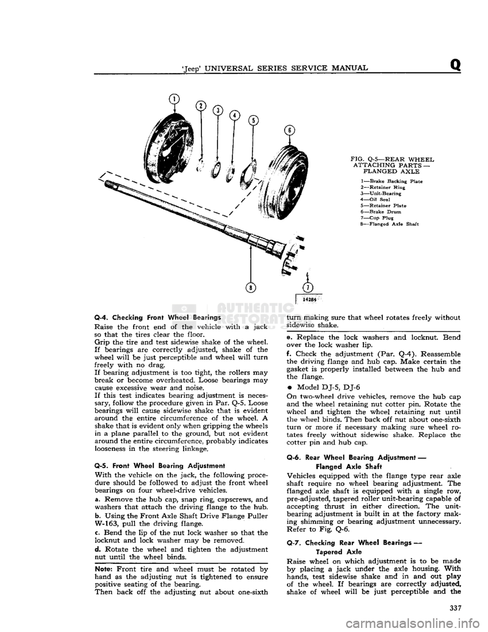
Vehicles
equipped with the
flange
type
rear
axle
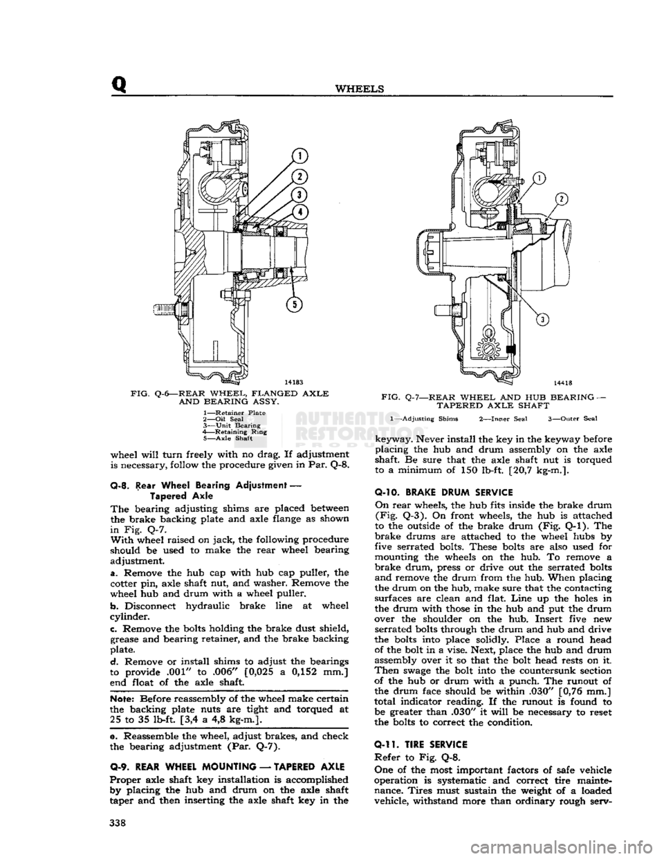
shaft require no wheel bearing adjustment. The flanged axle shaft is equipped with a single row,
pre-adjusted,
tapered roller unit-bearing capable of
accepting thrust in either direction. The unit-
bearing
adjustment is built in at the factory mak
ing shimming or bearing adjustment unnecessary.
Refer
to Fig. Q-6.
Q-7.
Checking
Rear
Wheel Bearings —
Tapered
Axle
Raise
wheel on which adjustment is to be made
by placing a
jack
under the axle housing.
With
hands,
test
sidewise shake and in and out play
of the wheel. If bearings are correctly adjusted,
shake of wheel
will
be just perceptible and the 337
Page 338 of 376
Q
WHEELS
FIG.
Q-6—REAR
WHEEL,
FLANGED
AXLE
AND
BEARING
ASSY.
1—
Retainer
Plate
2— Oil
Seal
3—
Unit
Bearing
4—
Retaining
Ring
5—
Axle
Shaft
wheel
will
turn
freely with no drag. If adjustment
is necessary, follow the procedure given in Par. Q-8.
Q-8.
Rear Wheel Bearing Adjustment
—
Tapered Axle
The
bearing adjusting shims are placed
between
the brake backing plate and axle flange as shown
in
Fig. Q-7.
With
wheel raised on
jack,
the following procedure
should be used to make the
rear
wheel bearing
adjustment.
a.
Remove the hub cap with hub cap puller, the
cotter pin, axle shaft nut, and washer. Remove the
wheel hub and drum with a wheel puller.
b.
Disconnect hydraulic brake line at wheel
cylinder.
c.
Remove the
bolts
holding the brake dust shield, grease and bearing retainer, and the brake backing
plate.
d.
Remove or install shims to adjust the bearings
to provide .001" to .006" [0,025 a 0,152 mm.]
end float of the axle shaft.
Note:
Before reassembly of the wheel make certain
the backing plate nuts are tight and torqued at 25 to 35 lb-ft [3,4 a 4,8 kg-m.].
e. Reassemble the wheel, adjust brakes, and check
the bearing adjustment (Par. Q-7).
0-9.
REAR WHEEL MOUNTING
—
TAPERED AXLE
Proper
axle shaft key installation is accomplished by placing the hub and drum on the axle shaft
taper and then inserting the axle shaft key in the
FIG.
Q-7—REAR
WHEEL
AND HUB
BEARING
—
TAPERED
AXLE
SHAFT
1—-Adjusting
Shims
2—Inner
Seal
3—Outer
Seal
keyway.
Never install the key in the keyway before
placing
the hub and drum assembly on the axle
shaft. Be sure that the axle shaft nut is torqued
to a minimum of 150 lb-ft. [20,7 kg-m.].
O-10.
BRAKE
DRUM
SERVICE
On
rear
wheels, the hub fits inside the brake drum
(Fig.
Q-3). On front wheels, the hub is attached
to the outside of the brake drum (Fig. Q-l). The
brake
drums are attached to the wheel hubs by
five serrated bolts. These
bolts
are also used for
mounting the wheels on the hub. To remove a
brake
drum,
press or drive out the serrated
bolts
and
remove the drum from the hub. When placing
the drum on the hub, make sure that the contacting
surfaces are clean and flat.
Line
up the
holes
in
the drum with
those
in the hub and put the drum
over the shoulder on the hub. Insert five new
serrated
bolts
through the drum and hub and drive
the
bolts
into place solidly. Place a round head of the bolt in a vise. Next, place the hub and drum
assembly over it so that the bolt head rests on it.
Then
swage
the bolt into the countersunk section of the hub or drum with a punch. The runout of
the drum face should be within .030" [0,76 mm.]
total indicator reading. If the runout is found to be greater than .030" it
will
be necessary to reset
the
bolts
to correct the condition.
0-11.
TIRE SERVICE
Refer
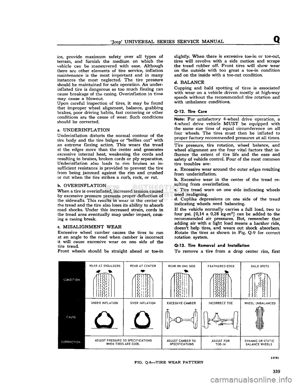
to Fig. Q-8.
One
of the most important factors of safe vehicle
operation is systematic and correct tire mainte nance.
Tires
must sustain the weight of a loaded vehicle, withstand more than ordinary rough serv- 338
Page 339 of 376
'Jeep'
UNIVERSAL
SERIES
SERVICE
MANUAL
Q
ice, provide maximum safety over all
types
of
terrain,
and furnish the medium on which the
vehicle can be maneuvered with ease. Although
there are other
elements
of tire service, inflation maintenance is the most important and in many
instances the most neglected. The tire pressure should be maintained for safe operation. An under- inflated tire is dangerous as too much flexing can
cause breakage of the casing. Overinflation in time
may
cause a blowout.
Upon
careful inspection of tires, it may be found
that improper wheel alignment, balance, grabbing
brakes,
poor driving habits, fast cornering or other
conditions are the cause of wear. Such conditions
should be corrected.
a.
UNDERINFLATION
Underinflation
distorts the normal contour of the
tire
body and the tire
bulges
or "bellies out" with
an
extreme flexing action.
This
wears the tread at the
edges
more than the center and generates
excessive internal heat, weakening the cords and
resulting
in bruises, broken cords or ply separation.
Underinflation
also leads to rim bruises as in sufficient resistance is provided to prevent the tire
from
being jammed against the rim and crushed
or
cut when the tire strikes a
curb,
rock, or rut.
b.
OVERINFLATION
When
a tire is
overinf
lated,
increased tension caused by excessive pressure prevents proper deflection of
the sidewalls.
This
results in wear in the center of the tread and the tire also
loses
its ability to absorb
road
shocks. Under this increased
strain,
cords in the tread area eventually snap under impact, causing a casing break.
c.
MISALIGNMENT
WEAR
Excessive
wheel camber causes the tires to run at an angle to the road when camber is incorrect
it
will
cause excessive wear on one side of the
tire
tread.
Front
wheels should be straight ahead or toe-in slightly. When there is excessive toe-in or
toe-out,
tires
will
revolve with a side motion and scrape
the tread rubber off.
Front
tires
will
show wear on the outside with too great a toe-in condition
and
on the inside with a
toe-out
condition.
d.
BALANCE
Cupping
and bald spotting of tires is associated
with
wear on a vehicle driven mostly at high-way
speeds
without the recommended tire rotation and
with
unbalance conditions.
Q-12.
Tire
Care
Note;
For satisfactory 4-wheel drive operation, a
4-wheel drive vehicle
MUST
be equipped with the same size tires of equal circumference on all
four wheels. The tires must then be inflated to
proper
factory recommended pressures at all times.
Tire
pressure, tire rotation, wheel balance, and wheel alignment are the four vital factors that in
fluence the
extent
of tire life and the
ease
and safety of vehicle control.
Four
of the most common
tire
troubles are:
a.
Excessive wear around the outer
edges
resulting
from
underinflation.
b.
Excessive wear in the center of the tread re
sulting from overinflation.
c.
Tire
tread worn on one side indicating wheels
need realigning.
d.
Cuplike
depressions on one side of the tread
indicating
wheels need balancing.
If
the vehicle normally carries a
full
load, two to
four psi. [0,14 a 0,28 kg-m2] can be added to the
recommended air pressures. But, remember that adding air with a light load means a harsher ride,
doesn't
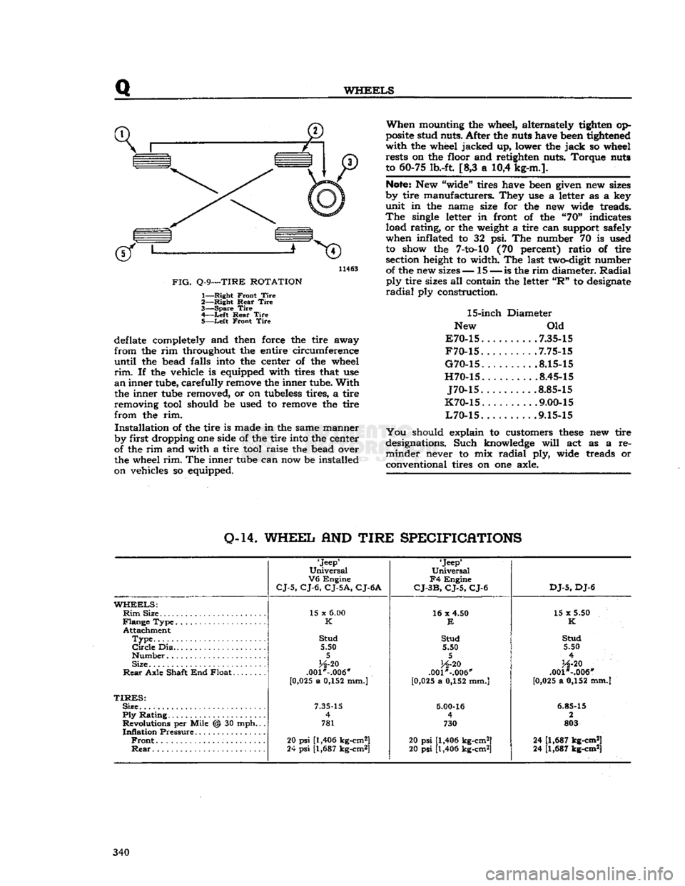
help tires, and wears out shock absorbers. Rotate the tires as shown in Fig. Q-9 for correct
rotation system.
Q-13.
Tire
Removal
and
Installation
To
remove a tire from a drop center rim, first
WEAR
AT SHOULDERS
WEAR
AT CENTER
WEAR
ON ONE
SIDE
FEATHERED
EDGE
BALD
SPOTS
/1TTDN
i
UNDER
INFLATION
OVER
INFLATION
EXCESSIVE
CAMBER
INCORRECT
TOE
WHEEL
UNBALANCED
liF
11
ADJUST
PRESSURE TO
SPECIFICATIONS
WHEN
TIRES ARE
COOL
ADJUST
CAMBER
TO
SPECIFICATIONS
ADJUST
FOR
TOE-IN
DYNAMIC
OR
STATIC
BALANCE
WHEELS
FIG.
Q-8—TIRE
WEAR
PATTERN
339
Page 340 of 376
Q
WHEELS
11463
FIG.
Q-9—TIRE
ROTATION
1—
Right
Front
Tire
2—
Right
Rear
Tire
3—
Spare
Tire
4—
-Left
Rear
Tire
5—
Left
Front
Tire
deflate completely and then force the tire away
from
the rim throughout the entire circumference
until
the bead falls into the center of the wheel
rim.
If the vehicle is equipped with tires that use
an
inner tube, carefully remove the inner tube.
With
the inner tube removed, or on tubeless tires, a tire
removing tool should be used to remove the tire
from
the rim.
Installation
of the tire is made in the same manner
by first dropping one side of the tire into the center
of the rim and with a tire tool raise the bead over
the wheel
rim.
The inner tube can now be installed
on vehicles so equipped.
When
mounting the wheel, alternately tighten op
posite stud nuts. After the nuts have been tightened
with
the wheel jacked up, lower the
jack
so wheel rests on the floor and retighten nuts. Torque nuts
to 60-75 lb.-ft. [8,3 a 10,4 kg-m.].
Note:
New "wide" tires have been given new sizes
by tire manufacturers. They use a letter as a key
unit
in the name size for the new wide treads.
The
single letter in front of the "70" indicates load rating, or the weight a tire can support safely
when inflated to 32 psi. The number 70 is used to show the
7-to-10
(70 percent) ratio of tire section height to width. The last two-digit number of the new sizes— 15 —
is
the rim diameter.
Radial
ply
tire sizes all contain the letter
"R"
to designate
radial
ply construction.
15-inch
Diameter
New Old
E70-15
7.35-15
F70-15
.7.75-15
G70-15
8.15-15
H70-15
8.45-15
J70-15
.8.85-15
K70-15
. .... .9.00-15
L70-15
9.15-15
You
should explain to customers
these
new tire
designations. Such knowledge
will
act as a re
minder
never to mix
radial
ply, wide treads or
conventional tires on one axle.
0-14.
WHEEL
AND
TIRE
SPECIFICATIONS
'Jeep'
Universal
V6
Engine
CJ-5,
CJ-6,
CJ-5A,
CJ-6A
'Jeep*
Universal
F4
Engine
CJ-3B,
CJ-5,
CJ-6
DJ-5,
DJ-6
WHEELS:
Rim
Size 15 x
6.00
16 x 4.50
15 x 5.50
K
E
K
Attachment
Type
Stud
Stud Stud
Circle
Dia 5.50 5.50 5.50
5 5
4
Size
H-20
H-20
H-20
Rear
Axle Shaft End Float .001*-.006"
.001"-.006" .001 *-.006"
[0 ,025 a 0,152 mm.)
[0,025 a 0,152 mm.] [0,025 a 0,152 mm.]
TIRES:
Size.
7.35-15
6.00-16
6.85-15
Ply
Rating 4
4 2
Revolutions per Mile @ 30 mph.. . 781 730 803
Inflation
Pressure
Front
20
psi
[1,406 kg-cm2]
20 psi [1,406 kg-cm2] 24 [1,687 kg-cm*]
Rear
24
psi
[1,687 kg-cm*]
20 psi [1,406 kg-cm2] 24 [1,687 kg-cm*] 340