JEEP CJ 1953 Service Manual
Manufacturer: JEEP, Model Year: 1953, Model line: CJ, Model: JEEP CJ 1953Pages: 376, PDF Size: 19.96 MB
Page 351 of 376
'Jeep'
UNIVERSAL
SERIES
SERVICE
MANUAL
T
BODY
Contents
SUBJECT
PAR.
Brake
and
Clutch
Pedal Pads T-7
Canvas
Tops T-5
Care
of
Fabric
Tops. : T-6
Front
Seat Adjustment. . . T-8
Passenger Seat Safety
Catch
. .T-9
Windshield
T-2, T-3
Windshield
Glass and Weatherstrip T-4
T-1.
GENERAL
The
body
is of
all
steel construction with mountings
that provide a secure attachment to the frame.
All
major panels are of No. 18
gauge
steel. All
open
edges
of the panels are turned under, reinforced
and
flanged to provide strength. These panels are reinforced with
"U"
sections
and welded. All com
ponent
panels are seamed and welded
together.
The
body
is insulated from the frame with insulator shims placed
between
the
body
and frame and
held in position by the
body
bolts.
The
instruments and controls, mounted on the
instrument panel are within clear view and easy
to reach.
Note:
A new floor pan cover plate has
been
released on late CJ-5 and CJ-6 models, that is
identified by a stamped oval-shaped bubble or
relief, located to the right of the accelerator treadle.
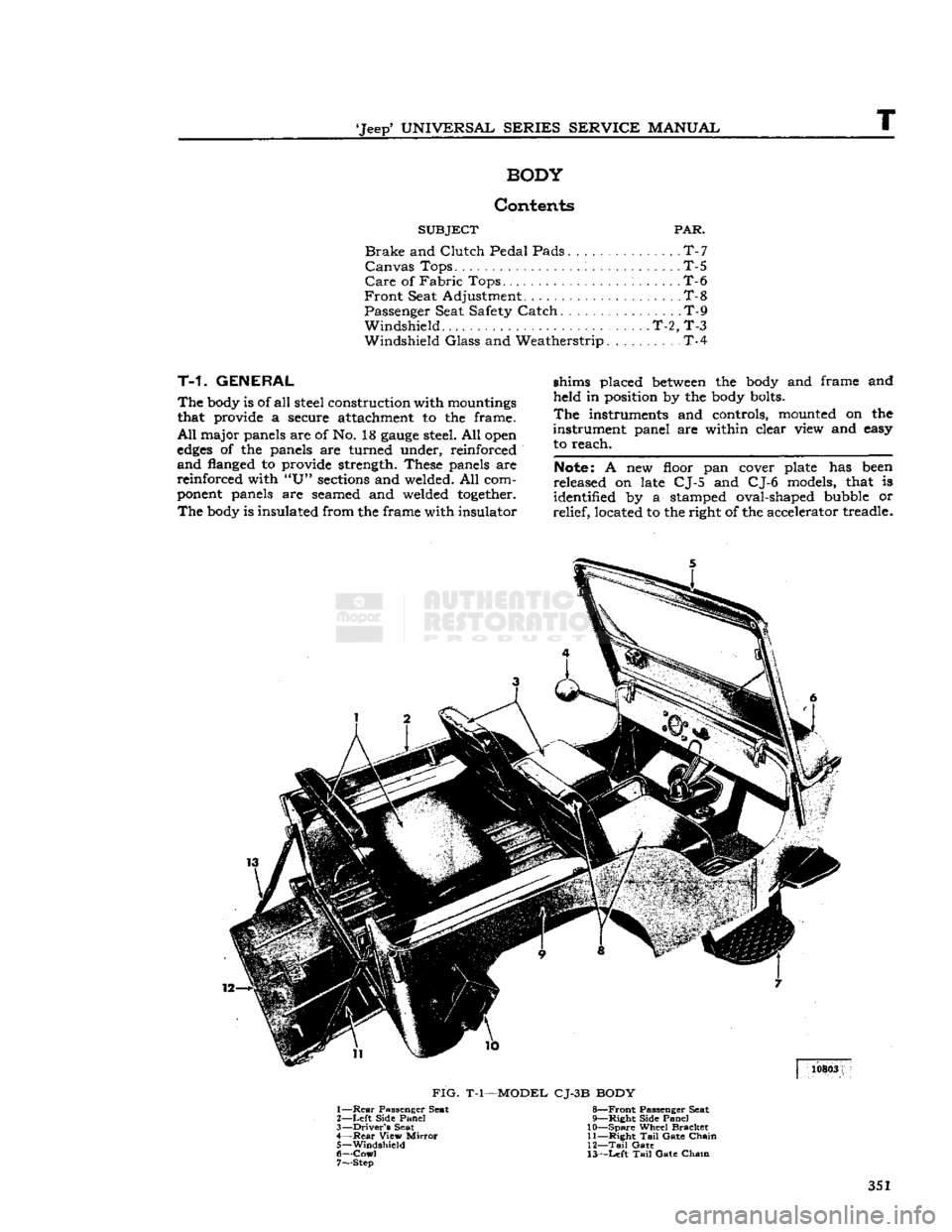
FIG.
T-l—MODEL CJ-3B BODY
1—
Rear
Passenger Seat 8—Front Passenger Seat
2—
Left
Side
Panel
9—Right Side
Panel
3—
Driver's
Seat 10—Spare Wheel
Bracket
4—
Rear
View
Mirror
11—Right
Tail
Gate
Chain
5—
Windshield
12—Tail
Gate
6—
Cowl
13—Left
Tail
Gate
Chain
7— Step
351
Page 352 of 376
BODY
10728
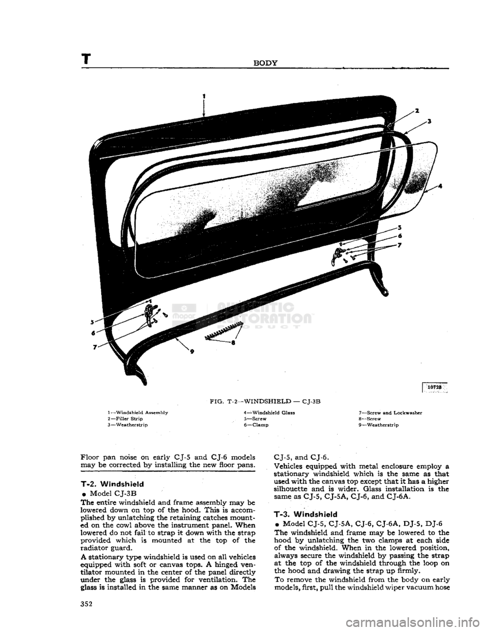
FIG.
T-2—WINDSHIELD
—
CJ-3B
1—
Windshield
Assembly
2—
Filler
Strip
3—
Weatherstrip 4—
Windshield
Glas3
5—
Screw
6—
Clamp
7—
Screw
and Lockwasher
8—
Screw
r
9— —Weatherstrip
Floor
pan
noise
on early CJ-5 and CJ-6
models
may be corrected by installing the new floor pans.
T-2.
Windshield
•
Model
CJ-3B
The
entire windshield and frame assembly may be
lowered down on top of the hood.
This
is accom plished by unlatching the retaining catches mount
ed on the cowl
above
the instrument panel. When lowered do not
fail
to strap it down with the strap provided which is mounted at the top of the
radiator
guard.
A
stationary
type
windshield is used on all vehicles
equipped with
soft
or canvas
tops.
A hinged ven tilator mounted in the center of the panel directly
under the
glass
is provided for ventilation. The
glass
is installed in the same manner as on Models
CJ-5,
and
CJ-6.
Vehicles equipped with metal enclosure employ a
stationary windshield which is the same as that used with the canvas top
except
that it has a higher
silhouette
and is wider.
Glass
installation is the same as
CJ-5,
CJ-5
A, CJ-6,
and
CJ-6
A.
T-3.
Windshield
»
Model
CJ-5, CJ-5A, CJ-6, CJ-6A,
DJ-5, DJ-6
The
windshield and frame may be lowered to the
hood
by unlatching the two clamps at each side
of the windshield. When in the lowered position, always secure the windshield by passing the strap
at the top of the windshield through the
loop
on the
hood
and drawing the strap up firmly.
To
remove the windshield from the
body
on early
models, first,
pull
the windshield wiper vacuum
hose
352
Page 353 of 376
'Jeep'
UNIVERSAL
SERIES SERVICE
MANUAL
T
353
Page 354 of 376
T
BODY
from the windshield wiper vacuum fitting. On
late
models
disconnect electrical wires from wiper
motor. Unlatch the two windshield clamps on each
side
of the windshield.
Fold
the windshield forward
until
the
slot
in the windshield
hinges
aligns with the flat
side
of the pin in the
body
hinges.
Slip wind
shield off the pins and remove from
body.
T-4.
Windshield Glass
The
windshield
glass
is mounted in a rubber
weatherstrip which in turn
mounts
in the frame. A
rubber
locking strip, which
holds
the
glass
firmly in
the frame, is inserted in a moulded
groove
around
the rear
face
of the weatherstrip as shown in Fig.
T-2.
To remove the
glass
it is necessary to first
remove the locking strip which may be pried out
with a screwdriver or similar
tool.
Installation is,
obvious.
T-5.
Canvas Tops
Canvas
tops
are available in
Half
Tops and
Full
Tops.
Installation instructions are provided with
each canvas top kit for each model vehicle.
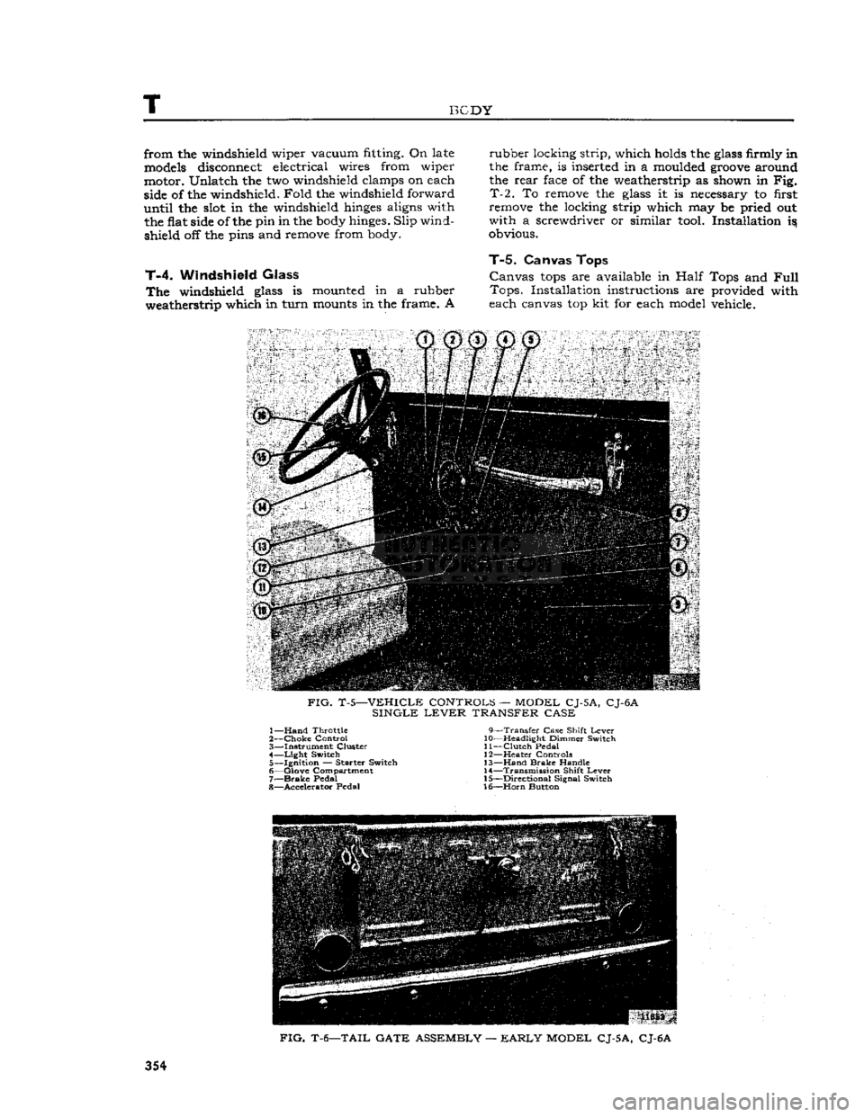
FIG.
T-5—VEHICLE CONTROLS — MODEL CJ-5A, CJ-6A
SINGLE
LEVER
TRANSFER CASE 1—
Hand
Throttle 9—Transfer Case Shift
Lever
2—
Choke
Control 10—Headlight Dimmer Switch
3— Instrument Cluster 11—Clutch Pedal 4—
Light
Switch 12—Heater Controls 5— Ignition — Starter Switch 13—Hand
Brake
Handle
6— Glove Compartment 14—Transmission Shift
Lever
7—
Brake
Pedal 15—Directional Signal Switch
8— Accelerator Pedal 16—Horn Button
FIG.
T-6—TAIL GATE ASSEMBLY —
EARLY
MODEL CJ-5A, CJ-6A
354
Page 355 of 376
'Jeep'
UNIVERSAL
SERIES
SERVICE
MANUAL
T
FIG.
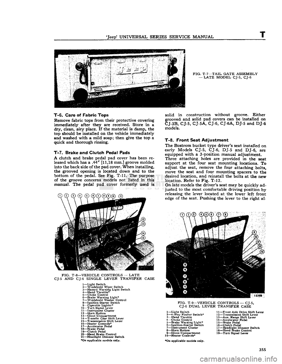
T-7—TAIL
GATE
ASSEMBLY
—
LATE
MODEL
CJ-5, CJ-6
T-6.
Care
of
Fabric
Tops
Remove fabric
tops
from their protective covering
immediately after they are received. Store in a
dry,
clean,
airy
place. If the material is damp, the
top should be installed on the vehicle immediately
and
washed with a mild soap; then
give
the top a
quick
and thorough rinsing.
T-7.
Brake
and
Clutch Pedal Pads
A
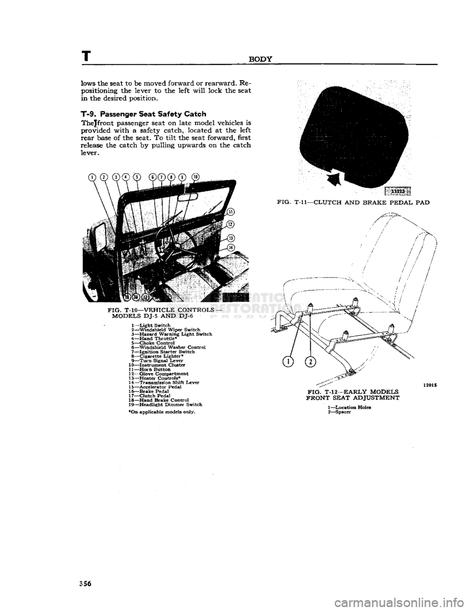
clutch and brake pedal pad cover has been re leased which has a .44" [11,18 mm.]
groove
molded into the back side of the pad cover. When installing,
the grooved opening is located down and to the
bottom
of the pedal. See Fig. T-ll. The purpose of the
groove
concerns models not listed in this
manual.
The pedal pad cover formerly used is
FIG.
T-8—VEHICLE
CONTROLS
—
LATE
CJ-5
AND CJ-6
SINGLE
LEVER
TRANSFER
CASE
1—
Light
Switch
2—
Windshield
Wiper
Switch
3—
Hazard
Warning
Light
Switch
4—
Hand
Throttle*
5—
Choke
Control
6—
Brake
Warning
Light*
7—
Windshield
Washer
Control
8—
Ignition
Starter
Switch
9—
Cigarette
Lighter*
10—
Turn
Signal
Lever
11—
Instrument
Cluster
12—
Horn
Button
13—
Glove
Compartment
14—
Transfer
Case
Shift
Lever
15—
Transmission
Shift
Lever
16—
^Heater
Controls*
17—
Accelerator
Pedal
18—
Brake
Pedal
19—
Clutch
Pedal
20—
Hand
Brake
Control
21—
Headlight
Dimmer
Switch
*On
applicable models only. solid in construction without groove.
Either
grooved and solid pad covers can be installed on
CJ-3B,
CJ-5,
CJ-5A,
CJ-6,
CJ-6A,
DJ-5 and DJ-6 models.
T-8.
Front Seat Adjustment
The
Bostrom bucket type driver's seat installed on
early
Models CJ-5, CJ-6, DJ-5 and DJ-6, are equipped with a 3-position manual adjustment.
Three
attaching
holes
are provided in the seat
support at the four seat mounting locations. To
adjust
the seat, remove the four attaching bolts,
move
the seat and four mounting spacers to the
desired
location, and reinstall the
bolts
at the new
location. Refer to Fig. T-12.
On
late models the driver's seat may be quickly ad
justed
to the most comfortable driving position by releasing the lever located at the lower left front
edge
of the seat. Pushing the lever to the right al-
CD CD®
®@©"®^
FIG.
T-9—VEHICLE
CONTROLS
—
CJ-5,
CJ-6
DUAL
LEVER
TRANSFER
CASE
1—
Light
Switch
2—4-Way
Flasher
Switch*
3—
Hand
Throttle
4—
Choke
Control
5—
Brake
Warning
Light*
6—
Ignition-Starter
Switch
7—
Instrument
Cluster
8—
Horn
Button
9—
Qlove
Compartment
10—Heater
Controls*
•On
applicable models only.
11—
Front
Axle
Drive
Shift
Lever
12—
Transmission
Shift
Lever
13—
Aux.
Range
Shift
Lever
14—
Accelerator
Pedal
15—
Brake
Pedal
16—
Clutch
Pedal
17—
Headlight
Dimmer
Switch
18—
Hand
Brake
Control
19—
Turn
Signal
Lever
355
Page 356 of 376
T
BODY
lows
the seat to be
moved forward
or
rearward.
Re
positioning
the
lever
to the
left
will
lock
the seat
in
the
desired position.
T-9.
Passenger
Seat
Safety
Catch
Thejfront
passenger seat on
late model vehicles
is
provided
with
a
safety
catch, located
at the
left
rear
base of the seat. To
tilt
the seat
forward,
first
release
the
catch
by
pulling
upwards
on the
catch lever. 11213
.
FIG.
T-ll—CLUTCH
AND
BRAKE PEDAL
PAD
FIG.
T-10—VEHICLE CONTROLS
-
MODELS
DJ-5 AND DJ-6 1—
Light
Switch
2— Windshield Wiper Switch
3—
Hazard
Warning Light Switch
4—Hand Throttle*
5—
choke
Control
6— Windshield
Washer
Control
7— Ignition
Starter
Switch
8— Cigarette Lighter* 9—
Turn
Signal Lever
10— Instrument Cluster
11—
Horn
Button
12— Glove Compartment
13—
Heater
Controls*
14— Transmission Shift Lever
15— Accelerator
Pedal
16—
Brake
Pedal
17—
Clutch
Pedal
18—
Hand
Brake Control
19— Headlight Dimmer Switch
*On
applicable
models
only.
FIG.
T-12—EARLY MODELS
FRONT SEAT
ADJUSTMENT
1—
Location Holes
2— Spacer
S5§
Page 357 of 376
'Jeep'
UNIVERSAL SERIES SERVICE
MANUAL
u
MISCEIiLaNEOUS
Contents
SUBJECT
PAR.
Abbreviations
U-15
Extra
Equipment U-2
Front
Bumper Weight U-9
Governor
U-3
Governor
Adjustment U-4
Governor
Maintenance. U-6
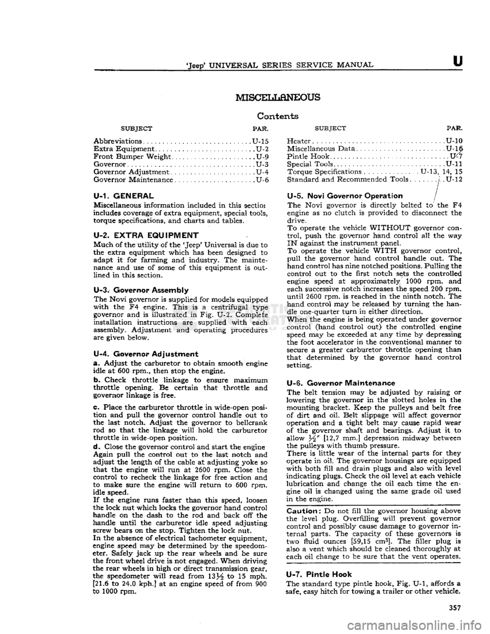
U-1. GENERAL
Miscellaneous information included in this sectioi
includes coverage of extra equipment, special
tools,
torque specifications, and charts and tables.
U-2. EXTRA
EQUIPMENT
Much
of the utility of the
*
Jeep*
Universal
is due to
the extra equipment which has been designed to adapt it for farming and industry. The mainte
nance and use of
some
of this equipment is out
lined
in this section.
U-3.
Governor Assembly
The
Novi governor is supplied for models equipped
with
the F4 engine.
This
is a centrifugal type governor and is illustrated in Fig. U-2. Complete
installation
instructions are supplied with each
assembly. Adjustment and operating procedures
are
given below.
U-4.
Governor Adjustment
a.
Adjust the carburetor to obtain smooth
engine
idle at 600 rpm., then
stop
the engine.
b.
Check
throttle linkage to ensure maximum
throttle opening. Be certain that throttle and
governor linkage is free.
c.
Place the carburetor throttle in wide-open posi tion and
pull
the governor control handle out to
the last notch. Adjust the governor to bellcrank
rod
so that the linkage
will
hold the carburetor
throttle in wide-open position.
d.
Close the governor control and start the
engine
Again
pull
the control out to the last notch and
adjust
the length of the cable at adjusting yoke so
that the
engine
will
run at
2600
rpm. Close the
control
to recheck the linkage for free action and
to make sure the
engine
will
return to 600 rpm.
idle speed.
If
the
engine
runs faster than this speed,
loosen
the lock nut which locks the governor hand control
handle on the dash to the rod and back off the
handle until the carburetor idle speed adjusting
screw
bears on the stop. Tighten the lock nut.
In
the absence of electrical tachometer equipment,
engine
speed may be determined by the speedom
eter. Safely
jack
up the
rear
wheels and be sure the front wheel drive is not
engaged.
When driving
the
rear
wheels in high or direct transmission gear,
the
speedometer
will
read from 13j^ to 15 mph. [21.6 to 24.0 kph.] at an
engine
speed of from 900
to 1000 rpm.
SUBJECT
PAR.
Heater
U-10 Miscellaneous Data U-16
Pintle
Hook 1X7
Special
Tools. U-ll
Torque
Specifications U-13, 14, 15
Standard
and Recommended Tools
j.
.U-12
U-5.
Novi Governor Operation /
The
Novi governor is directly belted to the F4
engine
as no clutch is provided to disconnect the
drive.
To
operate the vehicle
WITHOUT
governor con
trol,
push the governor hand control all the way
IN
against the instrument panel.
To
operate the vehicle
WITH
governor control,
pull
the governor hand control handle out. The
hand
control has nine notched positions. Pulling the
control
out to the first notch
sets
the controlled
engine
speed at approximately 1000 rpm. and each successive notch increases the speed 200 rpm.
until
2600
rpm. is reached in the ninth notch. The
hand
control may be released by turning the han dle one-quarter
turn
in either direction.
When
the
engine
is being operated under governor
control
(hand control out) the controlled
engine
speed may be
exceeded
at any time by depressing
the
foot
accelerator in the conventional manner to
secure a greater carburetor throttle opening than
that determined by the governor hand control
setting.
U-6.
Governor Maintenance
The
belt tension may be adjusted by raising or
lowering the governor in the slotted
holes
in the mounting bracket. Keep the pulleys and belt free
of
dirt
and oil. Belt slippage
will
affect governor
operation and a tight belt may cause
rapid
wear
of the governor shaft and bearings. Adjust it to
allow Yi' [12,7 mm.] depression midway
between
the pulleys with thumb pressure.
There
is little wear of the internal parts for they
operate in oil. The governor housings are equipped
with
both
fill
and
drain
plugs and also with level
indicating
plugs.
Check
the oil level at each vehicle
lubrication
and change the oil each time the en
gine
oil is changed using the same grade oil used
in
the engine.
Caution:
Do not
fill
the governor housing above
the level plug. Overfilling
will
prevent governor
control
and possibly cause damage to governor in
ternal
parts. The capacity of
these
governors is two fluid ounces [59,15 cm3]. The filler plug is
also a vent which should be cleaned thoroughly at
each oil change to be sure that the vent operates.
U-7.
Pintle Hook
The
standard type pintle hook, Fig. U-1, affords a
safe, easy hitch for towing a
trailer
or other vehicle. 357
Page 358 of 376
u
MISCELLANEOUS
Designed primarily for use on the road, a safety
latch
locks the hook in the closed position and two
eye
bolts
are provided for attachment of safety chains which should be crossed when installed, to
prevent the hooks from jumping out of the
eyes.
Keep
the attaching
bolts
tight at all times. When
lubricating
the vehicle, place a few drops of oil on the hook and safety latch pivot pins.
FIG.
U-l—PINTLE HOOK
U-8.
Pintle Hook Installation
Six
holes
are provided in the frame
rear
cross mem
bers of 'Jeep* Universals for the installation of
pintle hooks and safety chain eye bolts. On most vehicles, the pintle hook is attached using the top
four
holes
and the eye
bolts
are attached using the
lower two holes. On 'Jeep* Universals equipped
with
tail
gates,
the position of the hook and the eye must be changed to provide proper clearance.
On
these
vehicles, use the lower four
holes
for attaching the pintle hook and the upper two
holes
for
attaching the safety chain eye bolts.
U-9.
Front
Bumper
Weight
The
best
performance of a four-wheel drive vehicle
is obtained when the load is equally distributed for
traction
on the front and
rear
wheels.
This
weight
distribution is disturbed when the vehicle is used
for drawbar work as the load on the
rear
wheels is increased and that on the front wheels decreased.
The
addition of a 265 pound front bumper weight
equalizes the load.
When
the load is equalized the front and
rear
axles
do approximately the same work which results in
prolonged life of
these
parts and considerably more
satisfactory performance.
The
bumper weight, Fig. U-3, is held in place by
four
bolts
and is provided with hand
holes
for lift
ing.
Do not add sand
bags
or other
weights
in the vehicle. When driving over rough
terrain,
with the
weight in place, the driver should exercise due care.
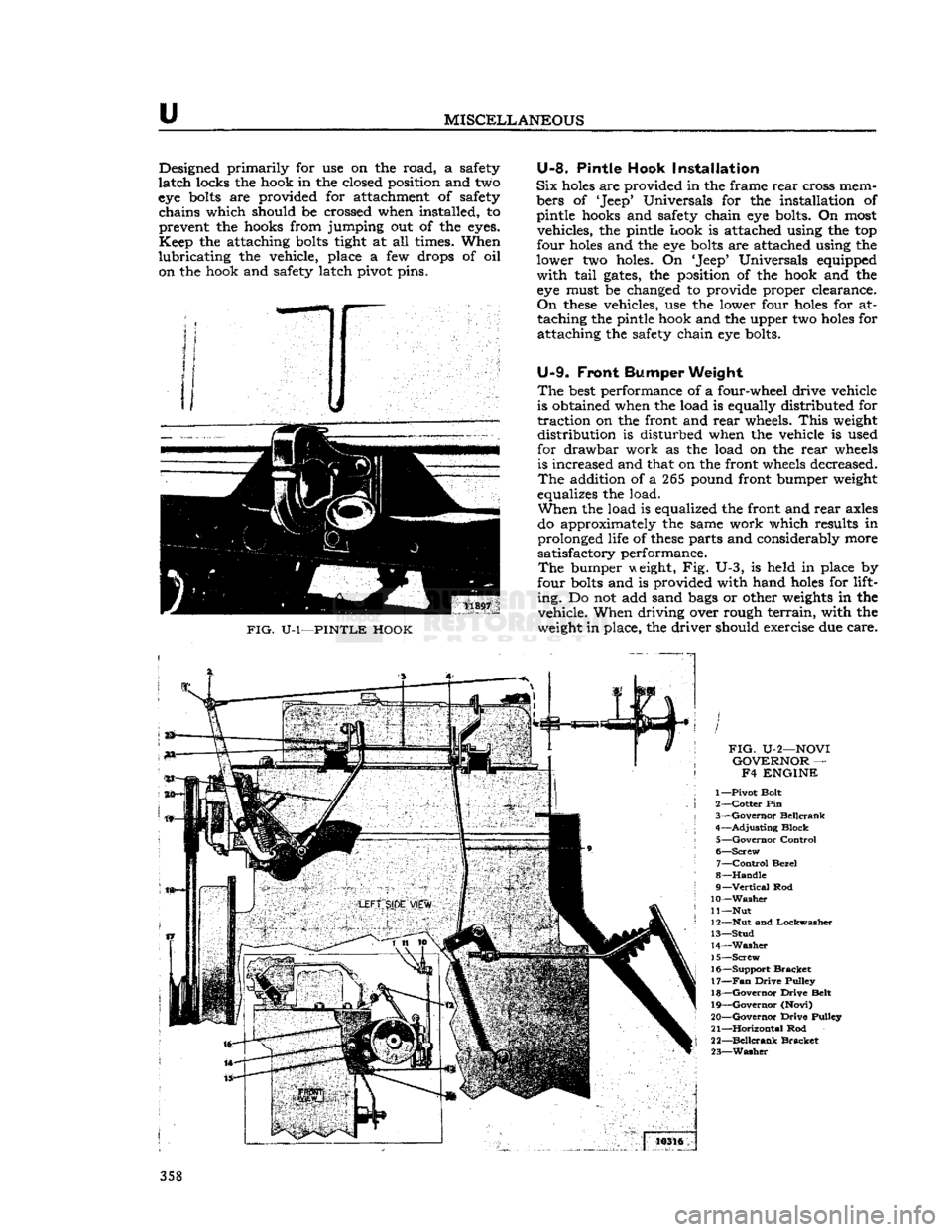
FIG.
U-2—NOVI
GOVERNOR
— F4 ENGINE
1—
Pivot
Bolt
2—
Cotter
Pin
3—
Governor
Beilcrank
4—
Adjusting
Block
5—
Governor
Control
6—
Screw
7—
Control
Bezel
8—
Handle
9—
Vertical
Rod
10—Washer
11
—Nut
12— Nut
and
Lockwasher
13—
Stud
14—
Washer
15—
Screw
16—
Support
Bracket
17—
Fan
Drive
Pulley
18—
Governor
Drive
Belt
19—
Governor
(Novi)
20—
Governor
Drive
Pulley
21—
Horizontal
Rod
22—
Beilcrank
Bracket
23—
Washer
358
Page 359 of 376
'Jeep*
UNIVERSAL
SERIES
SERVICE
MANUAL
U
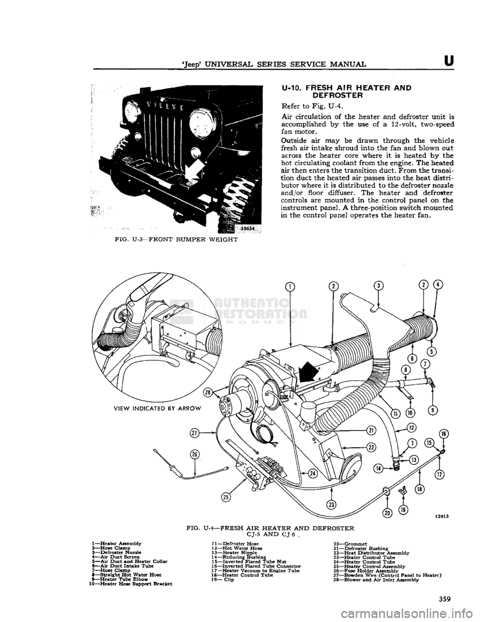
U-10. FRESH AIR HEATER AND
DEFROSTER
Refer to Fig. U-4.
Air
circulation of the
heater
and
defroster
unit
is
accomplished
by the use of a
12-volt,
two-speed
fan
motor.
Outside
air may be drawn
through
the
vehicle
fresh air
intake
shroud
into
the fan and
blown
out
across
the
heater
core
where
it is
heated
by the
hot circulating
coolant
from the
engine.
The
heated
air
then
enters
the transition
duct.
From the transi
tion
duct
the
heated
air
passes
into
the
heat
distri
butor
where
it is
distributed
to the
defroster
nozzle
and/or
floor
diffuser.
The
heater
and
defroster
controls
are
mounted
in the
control
panel
on the
instrument
panel. A
three-position
switch
mounted
in the
control
panel
operates
the
heater
fan.
FIG.
U-3—FRONT
BUMPER
WEIGHT
FIG.
U-4-
-FRESH
AIR
HEATER
AND
DEFROSTER
CJ-5
AND CJ-6 _ 1— Heater Assembly
2— Hose Clamp
3— Defroster
Nozzle
4—
Air
Duct Screen 5—
Air
Duct and Heater Collar
6—
Air
Duct Intake Tube 7— Hose Clamp
8— Straight Hot Water Hose
9— Heater Tube Elbow
10—Heater Hose Support Bracket
I
j—Defroster Hose
12— Hot Water Hose
13— Heater Nipple
14— Reducing Bushing
15— Inverted Flared Tube Nut
16— Inverted Flared Tube Connector
17— Heater Vacuum to Engine Tube
18— Heater Control Tube
19—
Clip
20— Grommet
21— Defroster Bushing
22— Heat Distributor Assembly
23— Heater Control Tube
24— Heater Control Tube
25— Heater Control Assembly
26—
Fuse
Holder Assembly
27— Bowden Wire (Control Panel to Heater)
28— Blower and Air Inlet Assembly 359
Page 360 of 376
u
MISCELLANEOUS
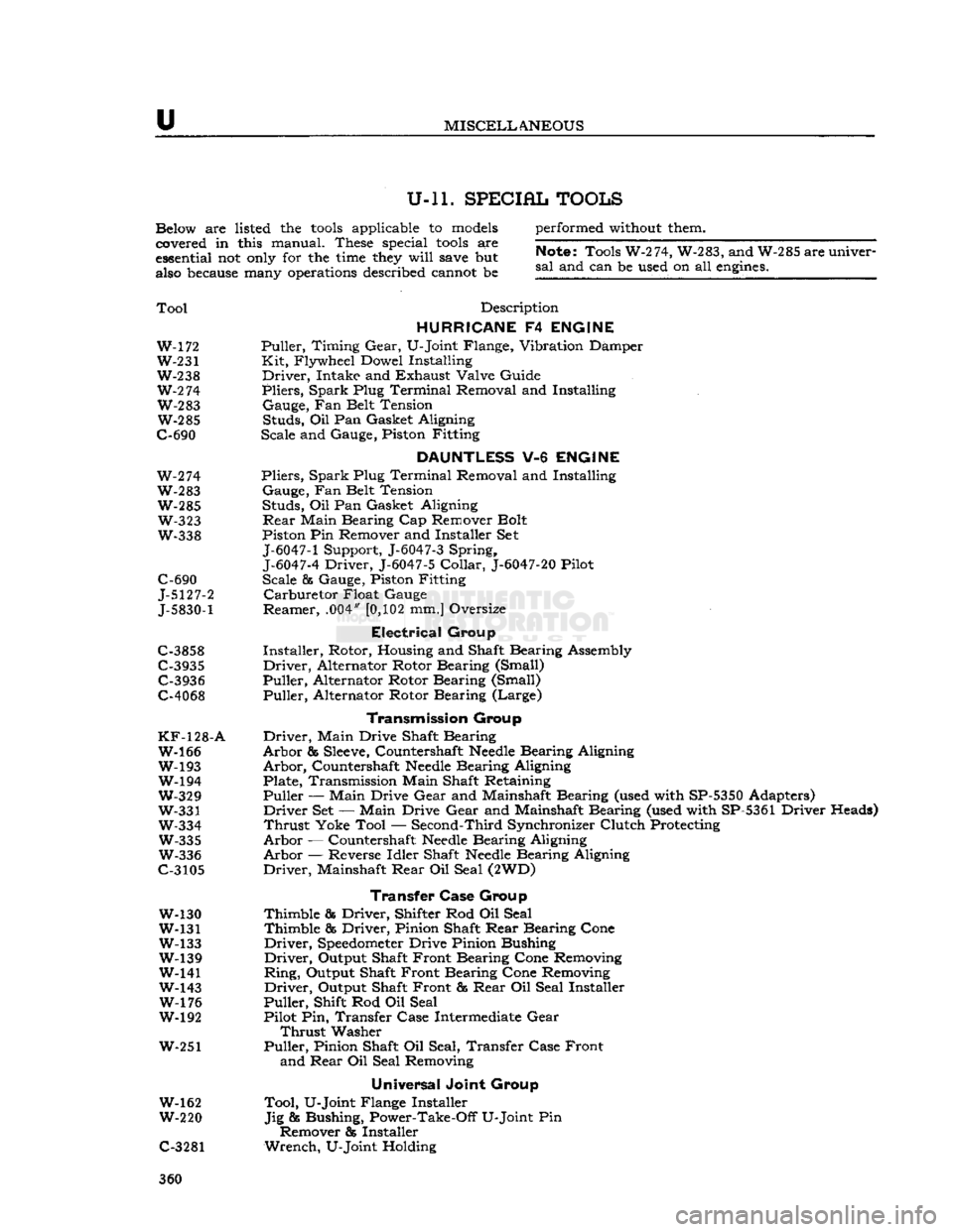
U-ll. SPECIAL TOOLS
Below are listed the
tools
applicable to
models
covered in this manual. These special
tools
are
essential not
only
for the
time
they
will
save
but
also
because
many
operations
described cannot be performed
without
them.
Note;
Tools W-274, W-283, and W-285 are univer
sal
and can be used on all
engines.
Tool
Description
HURRICANE
F4
ENGINE
W-172 Puller, Timing
Gear,
U-Joint Flange, Vibration Damper W-231 Kit, Flywheel Dowel Installing
W-238 Driver, Intake and Exhaust Valve Guide
W-2
74 Pliers, Spark Plug Terminal Removal and Installing W-283 Gauge, Fan Belt Tension W-285 Studs, Oil Pan Gasket Aligning
C-690 Scale and Gauge, Piston Fitting
DAUNTLESS
V-6
ENGINE
W-274 Pliers, Spark Plug Terminal Removal and Installing
W-283 Gauge, Fan Belt Tension W-285 Studs, Oil Pan Gasket Aligning W-323
Rear
Main Bearing Cap Remover Bolt
W-338 Piston Pin Remover and Installer Set
J-6047-1
Support, J-6047-3 Spring,
J-6047-4
Driver, J-6047-5
Collar,
J-6047-20
Pilot
C-690 Scale & Gauge, Piston Fitting
J-5127-2 Carburetor Float Gauge
J-5830-1
Reamer, .004"
[0,102
mm.] Oversize
Electrical
Group
C-3858 Installer, Rotor, Housing and Shaft Bearing Assembly
C-3935 Driver, Alternator Rotor Bearing (Small) C-3936 Puller, Alternator Rotor Bearing (Small)
C-4068 Puller, Alternator Rotor Bearing (Large)
Transmission
Group
KF-128-A
Driver, Main Drive Shaft Bearing W-166 Arbor &
Sleeve,
Countershaft
Needle
Bearing Aligning
W-193 Arbor, Countershaft
Needle
Bearing Aligning W-194 Plate, Transmission Main Shaft Retaining
W-329 Puller — Main Drive
Gear
and Mainshaft Bearing (used with SP-5350 Adapters)
W-331 Driver Set — Main Drive
Gear
and Mainshaft Bearing (used with SP-5361 Driver Heads)
W-334 Thrust Yoke Tool — Second-Third Synchronizer Clutch Protecting W-335 Arbor — Countershaft
Needle
Bearing Aligning
W-336 Arbor — Reverse Idler Shaft
Needle
Bearing Aligning
C-3105 Driver, Mainshaft
Rear
Oil Seal (2WD)
Transfer Case
Group
W-130 Thimble & Driver, Shifter Rod Oil Seal
W-131 Thimble & Driver, Pinion Shaft
Rear
Bearing Cone
W-133 Driver,
Speedometer
Drive Pinion Bushing W-139 Driver, Output Shaft Front Bearing Cone Removing
W-141 Ring, Output Shaft Front Bearing Cone Removing
W-143 Driver, Output Shaft Front &
Rear
Oil Seal Installer W-176 Puller, Shift Rod Oil Seal
W-192 Pilot Pin, Transfer Case Intermediate
Gear
Thrust
Washer
W-251 Puller, Pinion Shaft Oil Seal, Transfer Case Front and
Rear
Oil Seal Removing
Universal
Joint Group
W-162 Tool, U-Joint Flange Installer
W-220 Jig & Bushing, Power-Take-Off U-Joint Pin Remover & Installer
C-3281 Wrench, U-Joint Holding 360