JEEP CJ 1953 Service Manual
Manufacturer: JEEP, Model Year: 1953, Model line: CJ, Model: JEEP CJ 1953Pages: 376, PDF Size: 19.96 MB
Page 321 of 376
'Jeep'
UNIVERSAL
SERIES SERVICE
MANUAL
O
column assembly down through the floor pan open
ing and out from under vehicle.
0-24.
Disassembly
of
Steering
Gear
Refer
to Fig. 0-2.
When
the steering gear arm is installed on early
production vehicles, the line across the face of the
arm
and the end of the shaft should be in align ment. On later production vehicles, blind splines
on the lever shaft and in the steering gear arm en
sure
correct positioning of the arm.
a.
Remove the steering gear arm with a puller
C-3646.
Caution:
Do not use a hammer or
wedge
to re
move
the steering arm from the shaft and lever.
This
can cause damage to the shaft assembly.
b.
Loosen the lock nut and unscrew the adjusting
screw
two turns.
c.
Remove the side cover screws and washers. Re
move
the side cover and gasket.
d.
Remove lever shaft.
e.
Remove upper cover plate screws. Remove cam,
wheel tube, and bearing assembly from the housing.
f.
Clean
all parts with suitable cleaning solvent and wipe dry.
g.
After dismantling as outlined above is com
pleted, inspect cam
grooves
for wear, chipping and
scoring,
also the
ball
races on the cam ends and the
separate
ball
cups. Existence of any of
these
condi tions indicates the necessity for parts replacement.
h.
Inspect the tapered stud mounted on the lever
shaft for flat
spots
and chipping. In the case of
either, replacement is usually advisable. Inspect the
lever shaft for wear and
test
the fit of the shaft in
the bushings.
i.
Inspect condition of the oil seal at outer end of
lever shaft and the bearing at top end of steering
column.
0-25.
Reassembly
of
Steering
Gear
e Refer to Fig. 0-2.
Reassemble all parts to wheel tube in reverse order
of dismantling. Assemble cam, wheel tube and
bearing
assembly in housing, seating the lower
bearing
ball
cup in the housing.
Note:
New plastic retainer type cam bearings are
now available for the Ross steering gears. The new
bearings replace, and are interchangeable with,
the lock ring type cam bearings on gears equipped
with
early type cams.
With
adjusting shims in place, assemble upper
cover and adjust the cam bearings.
Assemble lever shaft in housing and with gasket
in
place assemble the side cover and set adjusting
screw
for a minimum backlash of the studs in the
cam
groove, with the steering gear at the center
point of travel.
When
assembling upper bearing spring and spring
seat in jacket tube make sure that the spring seat
is positioned correctly. It must be installed with
the lengthwise flange down against the bearing and
not up inside of spring coil.
0-26.
Installation
of
Steering
Gear
a.
After the gear has been properly adjusted, as
outlined in Par. 0-5, install steering gear assembly
in
chassis in the reverse order in which it was re
moved.
b.
After installing the assembly in the vehicle,
jack
up front of vehicle and place the front wheels
in
the straight ahead position.
c.
Temporarily install the steering wheel to locate
the mid-position of the steering gear. To locate the mid-position,
turn
the steering wheel as far to the
right
as possible and then
turn
in the
opposite
di
rection
as far as possible, noting the total number
of turns.
Turn
the wheel back just ^ of the total movement to place the gear in mid-position.
d.
With
the steering gear in mid-position and the
wheels in the straight ahead position install steer ing gear arm on lever shaft with the
ball
end down.
When
installed the line across the face of the arm
and
end of shaft should be in alignment.
0-27.
Steering
Wheel
Installation
•
Refer to Fig. 0-2.
a.
Install
steering wheel and spring on shaft.
Align
scribe marks on shaft and hub of wheel.
b.
Install
steering shaft nut and torque 20 to 25
lb-ft. [2,8 a 3,4 kg-m.].
c.
Install
horn cap. Test horn.
321
Page 322 of 376
o
STEERING
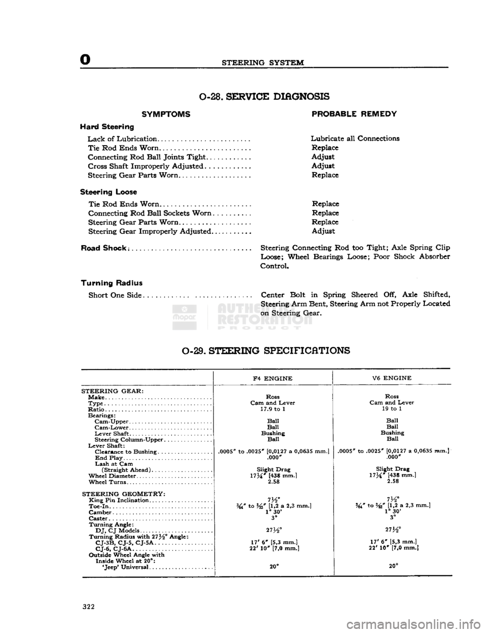
SYSTEM 0-28.
SBKF1CE
DIAGNOSIS
SYMPTOMS PROBABLE REMEDY
Hard Steering
Lack
of Lubrication Lubricate all Connections
Tie
Rod
Ends
Worn.
Replace
Connecting Rod
Ball
Joints
Tight. Adjust
Cross
Shaft Improperly Adjusted Adjust Steering
Gear
Parts
Worn...................
Replace
Steering
Loose
Tie
Rod
Ends
Worn
Replace
Connecting Rod
Ball
Sockets
Worn
Replace
Steering
Gear
Parts
Worn.
Replace
Steering
Gear
Improperly Adjusted.
......
Adjust
Road Shook; Steering Connecting Rod too Tight;
Axle
Spring
Clip
Loose; Wheel Bearings Loose;
Poor
Shock Absorber
Control,
Turning Radius
Short One
Side
Center
Bolt
in Spring
Sheered
Off,
Axle
Shifted, Steering Arm Bent, Steering Arm not Properly Located
on
Steering
Gear.
0-29.
STEERING
SPECIFICATIONS
F4
ENGINE
V6
ENGINE
STEERING
GEAR:
Make.
Ross
Ross
Type
Cam
and Lever
Cam
and Lever
Ratio..
17.9 to 1
19 to 1
Bearings:
Ball
Cam-Upper
Ball Ball
Cam-Lower
Ball Ball
Lever
Shaft Bushing
Bushing
Steering Column-Upper
Ball
Ball
Lever
Shaft:
.0005*
to
.0025"
[0,0127
a
0,0635
mm.]
Clearance
to Bushing
.0005"
to
.0025"
[0,0127
a
0,0635
mm.j
.0005*
to
.0025"
[0,0127
a
0,0635
mm.]
End
Play .000'
.000"
Lash
at Cam (Straight Ahead) Slight Drag
Slight Drag
Wheel Diameter.
17M*
(438 mm.]
17M*
[438 mm.]
Wheel
Turns.
2.58
2.58
STEERING
GEOMETRY:
King
Pin Inclination
m°
I
72
Toe-In.
W to W U,2 a 2,3 mm.] W to W [1,2 a 2,3 mm.]
Camber
1°
30'
1°
30'
Caster
3°
3°
Turning
Angle:
27K°
DJ,
CJ Models
27K° 273^°
Turning
Radius with 27^° Angle: 17' 6" [5,3 mm.]
CJ-3B,
CJ-5, CJ-5A.
17' 6" [5,3 mm.]
17' 6" [5,3 mm.]
CJ-6,
CJ-6A
22' 10" [7,0 mm.]
22' 10" [7,0 mm.]
Outside Wheel Angle with Inside Wheel at 20°:
20° 20°
322
Page 323 of 376
'Jeep'
UNIVERSAL
SERIES SERVICE
MANUAL
P
BRAKES
SUBJECT
PAR
GENERAL.
. P-l
Brake
Maintenance P-5
Master
Cylinder.
P-2
Parking
Brake
P-3
Transmission
Brake
P-4
BRAKE SERVICE
.P-6 Bleeding Brakes P-7
Brake
Adjustments P-14
Brake
Hoses P-8
Brake
Shoe
Initial
Adjustment P-l9
Brake
Shoe Installation P-l8
Brake
Pedal Adjustment P-9
Hand
Brake.
P-10 Inspection P-17
SUBJECT
PAR
Brake
Shoe Removal P-l6
Master
Cylinder Reconditioned. . P-20
Parking
Brake
Adjustment
.P-l 1
Relining
Transmission
Brake
P-13
Relining
Wheel
Brake
P-l5
Transmission
Brake
Adjustment .P-12
Wheel
Brake
Units P-14
Wheel
Cylinder Reconditioning P-21
TROUBLESHOOTING
P-2 2 Squeaky Brakes P-23
Rattles in Brakes P-24
SERVICE
DIAGNOSIS.
P-25
SPECIFICATIONS
P-2 6
P-1. GENERAL
A
double-safety
hydraulic brake system in con
junction with self-adjusting wheel brake units are
standard
equipment on all current production
'Jeep* vehicles. The
double-safety
brake system
Is
equipped with dual
stop
light switches that op
erate independently of each other, thus eliminating
possible
stop
light failure. Service information for
self adjusting brakes starts with Par. P-14.
All
four-wheel-drive vehicles are equipped with a transmission brake that operates in the drive line
and
is mounted to the rear of the transfer case. Two-wheel-drive vehicles
(DJ-5,
DJ-6)
are equipped
with a hand-operated parking brake that operates at the rear wheels.
P-2.
Master Cylinder —
Double Safety-Brake System
The
master cylinder (cast integrally with the res
ervoir)
is the compensating type. Refer to Fig.
P-2 and P-13.
Action by the brake pedal
moves
the master cylinder piston which exerts pressure on the fluid in
the cylinder and lines. 12914
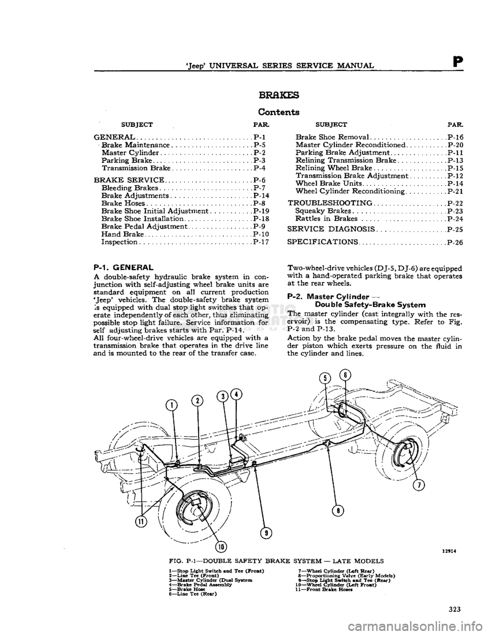
FIG.
P-l—DOUBLE SAFETY BRAKE SYSTEM —
LATE
MODELS 1— Stop Light Switch and Tee (Froat)
2—
Line
Tee (Front)
3—
Master
Cylinder (Dual System
4—
Brake
Pedal Assembly 5—
Brake
Hose
6—
Line
Tee
(Rear)
7—
Wheel
Cylinder (Left
Rear)
8— Proportioning Valve
(Early
Models)
9— —Stop Light Switch and Tee
(Rear)
10—
Wheel
Cylinder (Left Front)
11—
Front
Brake
Hoses
323
Page 324 of 376
p
BRAKES
13264
FIG- P-2—DOUBLE
SAFETY BRAKE
MASTER
CYLINDER
With
the Double-Safety brake system type master
cylinder,
failure
in one part of the brake system
does
not result in
failure
of the entire hydraulic
brake system. Failure in the
front
brake system
will
leave the rear brake system
still
operative or
failure
in
the rear system
will
leave the
front
brake system
operative.
A
double hydraulic
cylinder
with
two outlets, two
residual
check valves, two
fluid
reservoirs, and
two
hydraulic pistons (a
primary
and secondary)
are operated in tandem by a single hydraulic push
rod.
The
primary
outlet is connected to the
front
brakes
with
the secondary outlet connected to the rear brakes.
With
the master
cylinder
fluid
reservoirs
filled
and the
front
and rear brake system
bled,
there is a
solid
column
of
fluid
on the
forward
side of both the
primary
and the secondary pistons.
Upon
application
of the brakes, through movement
of
the brake pedal,
fluid
is displaced by the pistons
into
the wheel cylinders to activate both
front
and
rear brakes.
Upon
release
of the brakes,
fluid
re
turns
from
the rear wheel cylinders through the secondary residual check valve to the secondary
portion
of the master
cylinder
bore.
Fluid
also
returns
from
the
front
wheel cylinders through the
primary
residual check valve to the
primary
portion
of the master
cylinder
bore.
P-3.
Parking
Brakes
— DJ-5, DJ-6
a.
The parking brake is operated by a T-handle
lever
mounted to the
left
of the steering
column
and
suspended
from
the instrument panel. When
the brake lever is
pulled
outward, tension is exerted
on
the parking brake cable leading to the brake.
The
amount of brake
grip
depends
on the number
of
notches the lever is
pulled
out. To set the park
ing
brake,
pull
out on the parking brake
control
T-handle.
To
release
the brake,
turn
the handle
slightly
and push it
forward.
0
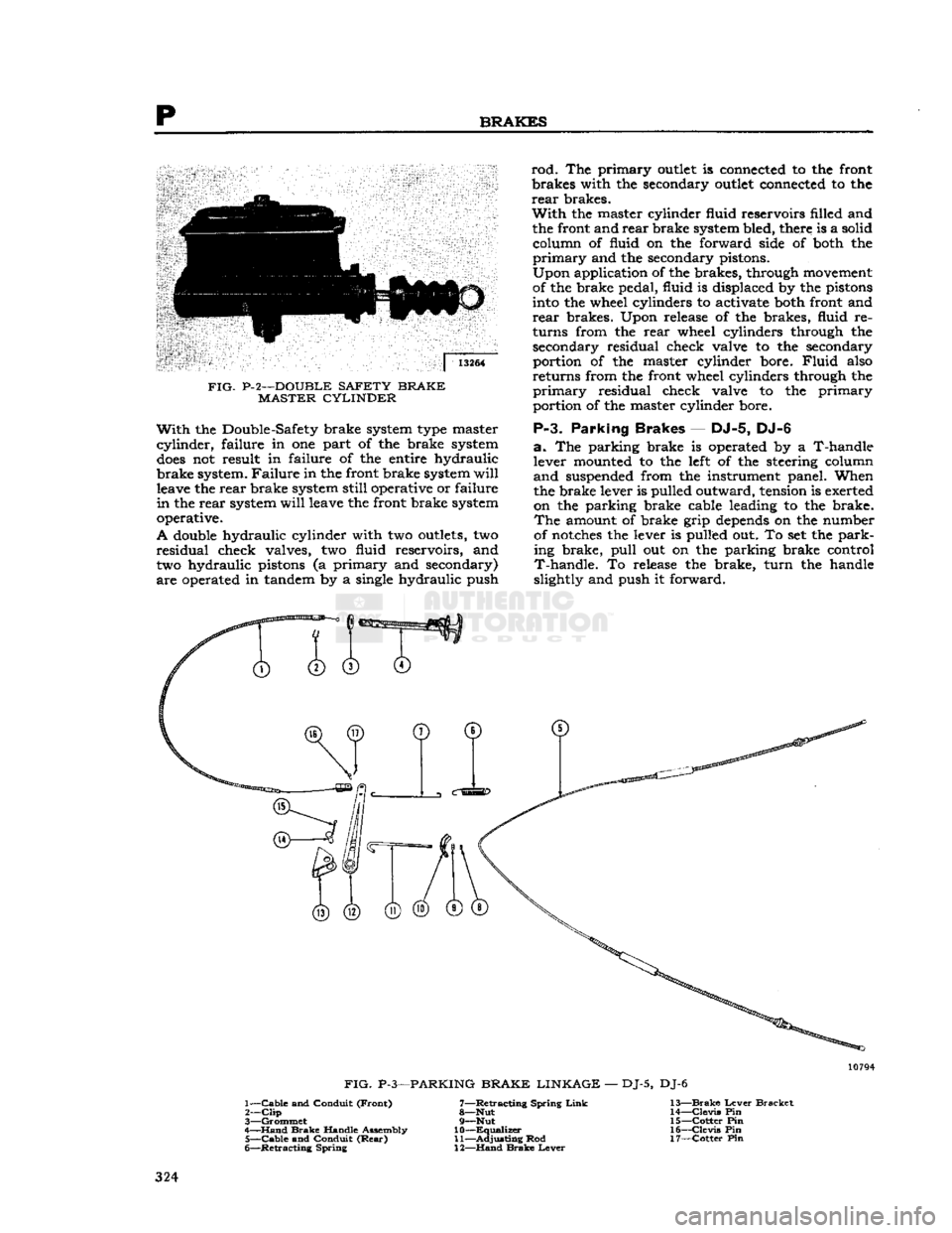
FIG.
P-3—PARKING
BRAKE LINKAGE
—
DJ-5,
DJ-6
1—
Cable
and
Conduit
(Front)
7—Retracting
Spring
Link
13—Brake
Lever
Bracket
2—
Clip
8—Nut
14—Clevis
Pin
3—
Grommet
9—Nut
15—Cotter
Pin
4—
Hand
Brake
Handle
Assembly
10—Equalizer
16—Clevis
Pin
5—
Cable
and
Conduit
(Rear)
11—Adjusting
Rod
17—Cotter
Pin
6—
Retracting
Spring
12—Hand
Brake
Lever
324
Page 325 of 376
'Jeep'
UNIVERSAL
SERIES SERVICE
MANUAL
P The
standard parking brakes (Fig. P-3) consist of
cable-controlled linkage for applying the rear wheel
brake
shoes
mechanically. A single cable from the
parking
brake control lever is connected, by means of an equalizer, to cables leading to individual rear
brakes.
A lever attached to the secondary
shoe,
with a link acting against the
primary
shoe,
expands the
shoes
into
contact with the drums.
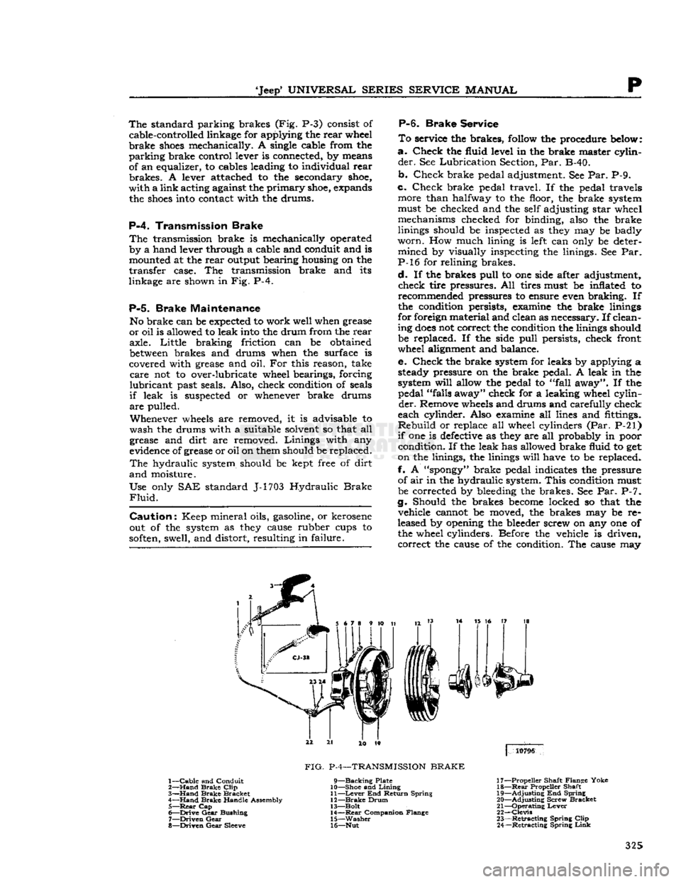
P-4.
Transmission Brake
The
transmission brake is mechanically operated
by a hand lever through a cable and conduit and is mounted at the rear output bearing housing on the
transfer case. The transmission brake and its
linkage are shown in Fig. P-4.
P-5.
Brake Maintenance
No brake can be
expected
to work well when grease
or oil is allowed to leak
into
the drum from the rear axle. Little braking friction can be obtained
between
brakes and drums when the surface is
covered with grease and oil. For this reason, take
care
not to over-lubricate wheel bearings, forcing
lubricant
past seals. Also, check condition of seals
if
leak is suspected or whenever brake drums
are
pulled.
Whenever
wheels
are removed, it is advisable to
wash the drums with a suitable solvent so that all
grease and dirt are removed. Linings with any
evidence of grease or oil on them should be replaced.
The
hydraulic system should be kept free of dirt
and
moisture.
Use only SAE standard J-1703 Hydraulic
Brake
Fluid.
Caution:
Keep mineral oils, gasoline, or kerosene
out of the system as
they
cause rubber cups to
soften,
swell, and distort, resulting in failure.
P-6.
Brake
Service
To
service the brakes,
follow
the procedure
below:
a.
Check the fluid level in the brake master cylin
der.
See Lubrication Section, Par. B-40.
b. Check brake pedal adjustment. See Par. P-9.
c. Check brake pedal travel. If the pedal travels more than halfway to the floor, the brake system
must be checked and the self adjusting star wheel mechanisms checked for binding, also the brake
linings should be inspected as
they
may be badly
worn.
How much lining is
left
can only be deter mined by visually inspecting the linings. See Par.
P-l6 for relining brakes.
d.
If the brakes pull to one side after adjustment, check tire pressures. All tires must be inflated to recommended pressures to ensure even braking. If
the condition persists, examine the brake linings
for foreign material and clean as necessary. If clean
ing
does
not correct the condition the linings should be replaced. If the side pull persists, check front
wheel alignment and balance.
e. Check the brake system for leaks by applying a steady pressure on the brake pedal. A leak in the
system
will
allow the pedal to "fall away". If the pedal "falls away" check for a leaking wheel cylin
der.
Remove
wheels
and drums and carefully check
each cylinder. Also examine all lines and fittings.
Rebuild
or replace all wheel cylinders (Par. P-21)
if
one is
defective
as
they
are all probably in poor condition. If the leak has allowed brake fluid to get
on the linings, the linings
will
have to be replaced.
f. A
"spongy"
brake pedal indicates the pressure of air in the hydraulic system.
This
condition must
be corrected by bleeding the brakes. See Par. P-7.
g. Should the brakes
become
locked so that the vehicle cannot be moved, the brakes may be re
leased by opening the bleeder screw on any one of the wheel cylinders. Before the vehicle is driven, correct the cause of the condition. The cause may
3
14 15 16 17 18
4
10796
1—
Cable
and Conduit
2—
Hand
Brake
Clip
3—
Hand
Brake
Bracket
4—
Hand
Brake
Handle Assembly 5—
Rear
Cap
6—
Drive
Gear
Bushing
7—
Driven
Gear
8—
Driven
Gear
Sleeve
FIG.
P-4—TRANSMISSION
BRAKE
9—Backing
Plate
10— Shoe and
Lining
11—
Lever
End Return Spring
12—
Brake
Drum
13— Bolt 14—
Rear
Companion Flange
15—
Washer
16— Nut 17— Propeller Shaft Flange Yoke
18—
Rear
Propeller Shaft
19—
Adjusting
End Spring
20—
Adjusting
Screw Bracket
21—
Operating
Lever
22—
Clevis
23—
Retracting
Spring
Clip
24—
Retracting
Spring
Link
325
Page 326 of 376
p
BRAKES
be either a defective master cylinder or the use of
low grade brake fluid which has expanded because
of heat. Use standard duty brake fluid conforming to
SAE-J1703
specification.
P-7.
Bleeding
Brakes
The
hydraulic
brake system must be bled whenever
a
fluid line has been disconnected or air
gets
into the system. A leak in the system may sometimes
be indicated by the presence of a spongy brake
pedal.
Air trapped in the system is compressible
and
does
not permit the pressure, applied to the
brake
pedal, to be transmitted solidly through to
the brakes. The system must be absolutely free
from
air at all times. When bleeding brakes, bleed
at that wheel with the
longest
line from the master
FIG.
P-5—BLEEDING
BRAKES
1—Bleeder
Screw
cylinder
first, the next
longest
second, etc. During
the bleeding operation the master cylinder must
be kept at least %
full
of hydraulic brake fluid.
To
bleed the brakes, first carefully clean all
dirt
from
around the master cylinder filler plug. If
bleeder tank is used follow the manufacturers in
structions.
Remove the filler plug and
fill
the master
cylinder
to the lower
edge
of filler neck.
Clean
off
all
bleeder connections at all four wheel cylinders.
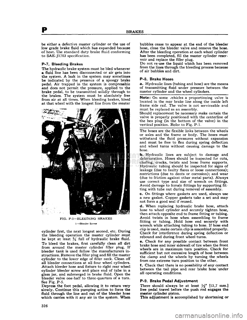
Attach
bleeder
hose
and fixture to right
rear
wheel
cylinder
bleeder screw and place end of tube in a
glass jar, and submerged in brake fluid. Open the bleeder valve one-half to three-quarters of a
turn.
See
Fig.
P-5.
Depress the
foot
pedal, allowing it to return very
slowly. Continue this pumping action to force the
fluid
through the line and out of the bleeder
hose
which
carries with it any air in the system. When bubbles cease to appear at the end of the bleeder
hose, close the bleeder valve and remove the hose.
After
the bleeding operation at each wheel cylinder
has been completed,
fill
the master cylinder reser
voir
and replace the filler plug.
Do not re-use the liquid which has been removed
from
the lines through the bleeding process because
of air bubbles and
dirt.
P-8.
Brake Hoses
a.
Hydraulic
lines (tubing and hose) are the means
of transmitting fluid under pressure between the master cylinder and the wheel cylinders.
Note:
On
some
vehicles a proportioning valve is
located in the
rear
brake line along the inside left
frame
side
rail.
The valve is not serviceable and
must be replaced as an assembly.
Should
replacement be necessary make certain the valve is properly positioned with the centerline of
the hex plug (in the bottom of the valve) in the
vertical
position. Refer to Fig. P-l.
The
hoses
are the flexible links between the wheels
or
axles and the frame or body. The
hoses
must
withstand
the fluid pressures without expansion
and
must be free to flex during spring deflection
and
wheel turns without causing damage to the
hose.
b.
Hydraulic
lines are subject to damage and
deterioration. Hoses should be inspected for cuts,
chafing,
cracks,
twists and
loose
frame supports.
Hydraulic
tubing should be inspected for signs of
leakage (due to faulty flares or
loose
connections);
restrictions
(due to dents or corrosion); and wear (due to friction against other metal parts). Always
use correct type and size of wrench on fittings.
Avoid
damage to female fittings by supporting fit
ting with tube nut during removal of assembly.
c.
On fittings where gaskets are used, always use
a
new gasket. Copper gaskets take a set and may
not form a
good
seal if reused.
d.
When replacing hydraulic brake hose, attach
hose
to wheel cylinder and securely tighten hose,
then attach
opposite
end to frame fitting or tubing.
Avoid
twists in
hose
when assembling to frame fitting
or
tubing. Hold
hose
end securely with
wrench
while attaching tubing to hose. If
hose
end
clip
is used, make certain clip is assembled properly.
Check
for interference during spring deflection or
rebound and during front wheel turns.
e.
Check
for any possible contact between front
brake
hose
and inner sidewall of tire when the front
wheels are in maximum
turn
position.
Check
for sufficient but not excessive length of
hose
between
the clamp and the wheels by turning the wheels
from
one extreme
turn
position to the otherl
f.
Check
that there is no possibility of any contact between the
tail
pipe and
rear
brake
hose
under
all
operating conditions.
P-9.
Brake Pedal Adjustment
There
should always be at least W [12,7 mm.]
free pedal travel before the push rod
engages
the master cylinder piston.
This
adjustment is accomplished by shortening or 326
Page 327 of 376
'Jeep'
UNIVERSAL
SERIES SERVICE
MANUAL
P
lengthening of the brake master cylinder eye bolt.
This
is
done
so the primary cup
will
clear the by
pass port when the piston is in the off position,
otherwise the compensating action of the master
cylinder
for expansion and contraction of the fluid
in
the system, due to temperature changes,
will
be destroyed and cause the brakes to drag.
Note:
Some older 'Jeep' vehicles may
develop
side
movement
of the clutch and brake pedals resulting
from wear of the pedals, shafts, and bushings. One
way to
compensate
for this wear is to install a pedal
slack
adjuster kit,
Part
No.
921936.
FIG.
P-6—HAND
BRAKE
ADJUSTMENT
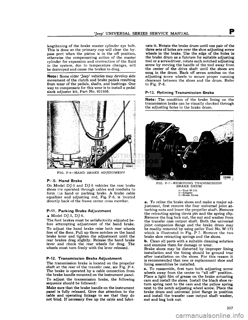
P-10.
Hand Brake
On
Model DJ-5 and DJ-6 vehicles the rear brake
shoes
are operated through cables and conduits to
form the hand or parking brake. A brake cable
equalizer and adjusting rod, Fig. P-6, is located directly back of the frame center cross member.
P-11.
Parking Brake Adjustment
•
Model DJ-5, DJ-6.
The
foot
brakes must be satisfactorily adjusted be
fore attempting adjustment of the hand brake.
To
adjust the hand brake raise both rear
wheels
free of the floor.
Pull
up three
notches
on the hand
brake
lever and tighten the adjustment until the
rear
brakes drag slightly. Release the hand brake
lever and check the rear
wheels
for drag. The
wheels
must turn freely with the lever released.
P-12.
Transmission Brake Adjustment
The
transmission brake is located on the propeller
shaft at the rear of the transfer case, see Fig. P-4.
The
brake is operated by a cable connection from
the brake handle mounted on the instrument panel.
To
adjust the transmission brake, the following
sequence
should be followed:
Make
sure that the brake handle on the instrument
panel is fully released. Give due attention to the
cable and operating linkage to see that
they
do
not bind. If necessary free up the cable and
lubri
cate it. Rotate the brake drum until one pair of the
three
sets
of
holes
are over the
shoe
adjusting screw
wheels
in the brake. Use the
edge
of the
holes
in
the brake drum as a fulcrum for suitable adjusting
tool
or a screwdriver, rotate each notched adjusting
screw by moving the handle of the
tool
away from
the center of the drive shaft until the
shoes
are
snug in the drum.
Back
off seven
notches
on the
adjusting screw
wheels
to secure proper running clearance
between
the
shoes
and the drum. Refer
to Fig. P-8.
P-13.
Relining Transmission Brake
Note:
The condition of the brake lining on the
transmission brake can be visually checked through
the adjusting
holes
in the brake drum.
FIG.
P-7—REMOVING
TRANSMISSION
BRAKE
DRUM
1— Tool W-172
2—
Adapter
3—
Brake
Drum
a.
To reline the brake
shoes
and make a major ad
justment, first remove the four universal joint at taching nuts and lower the propeller shaft. Remove
the retracting spring clevis pin and the spring clip.
Remove the hug lock nut, the nut and washer from
the transfer case output shaft. Both the universal
joint companion
flange
and the brake drum may be readily removed by using puller Tool No. W-172
which
is illustrated in Fig. P-7. Remove the two
brake
shoe
retracting springs and the
shoes.
b. Clean all parts with a suitable cleaning solution
and
examine them for damage or wear.
Brake
shoes
may be distorted by improper lining
installation and the lining should be ground true
after installation on the
shoes.
For this reason it
is recommended that new or replacement
shoe
and
lining assemblies be installed.
c. To reassemble, first turn both adjusting screw
wheels
away from the center to "all off" position.
Place a light film of grease on the brake actuating
cam
and install the
shoes.
Install the black
shoe
re
turn
spring next to the cam and the yellow spring next to the notch adjusting wheel screw. Place the
brake
drum and universal joint
flange
in position
and
install the transfer case output shaft washer,
nut and hug lock nut. 327
Page 328 of 376
p
BRAKES
PIG.
P-8—TRANSMISSION
BRAKE
ADJUSTMENT
1—
Bail
Nut
2— s,6"
12,38 mm.I
Clearance
3—
Adjusting
Screw
d.
Rotate the
drum
until
one pair of holes in the
drum
are opposite the two adjusting screw wheels
in
the brakes. Use the
edge
of the holes as a
fulcrum
and
with
a suitable
tool
or screwdriver for
adjusting,
rotate the adjusting screw wheels,
mov
ing
the handle of the
tool
away
from
the
drum
until
the
shoes
are snug in the
drum.
e.
Examine the brake operating cable to be
sure
that
it is not
worn
or damaged. Free it up thorough
ly
and lubricate
it.
Make
sure
the operating handle
on
the instrument panel is
fully
released.
Adjust
the clevis on the brake end of the operating cable
until
the clevis pin
will
just go through the hole
in
the clevis and brake operating lever
without
slack
in the cable.
Tighten
the clevis
lock
nut.
f.
After
the cable is connected back off seven
notches on each adjusting screw wheel
which
will
give
the proper
running
clearance between the
lining
and the
drum.
g.
Reconnect the propeller shaft.
Install
retracting
spring
clip,
clevis pin and the cotter pin, also, in
stall
the retracting spring
link
and spring.
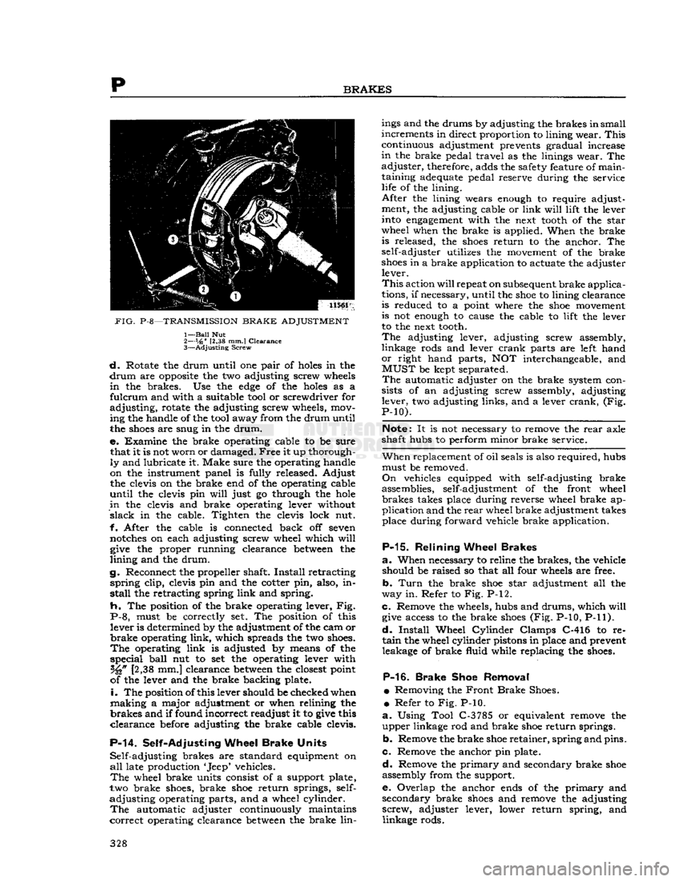
h. The
position
of the brake operating lever, Fig.
P-8, must be correctly set. The
position
of this
lever
is determined by the adjustment of the cam or
brake operating
link,
which
spreads
the two
shoes.
The
operating
link
is adjusted by
means
of the
special
ball
nut to set the operating lever
with
[2,38
mm.] clearance between the closest
point
of
the lever and the brake backing plate.
i.
The
position
of
this
lever should be checked when
making
a major adjustment or when
relining
the
brakes and
if
found
incorrect readjust it to give this
clearance before adjusting the brake cable
clevis.
P-14.
Self-Adjusting
Wheel
Brake
Units
Self-adjusting
brakes are standard equipment on
all
late production
'Jeep'
vehicles.
The
wheel brake units consist of a support plate,
two
brake
shoes,
brake
shoe
return springs, self-
adjusting
operating parts, and a wheel
cylinder.
The
automatic adjuster continuously maintains
correct
operating clearance between the brake
lin
ings
and the drums by adjusting the brakes
in
small
increments in direct
proportion
to
lining
wear. This
continuous
adjustment prevents gradual increase
in
the brake pedal
travel
as the
linings
wear. The
adjuster, therefore,
adds
the safety feature of
main
taining
adequate
pedal reserve
during
the service
life
of the
lining.
After
the
lining
wears enough to require adjustment, the adjusting cable or
link
will lift
the lever
into
engagement
with
the next
tooth
of the
star
wheel
when the brake is applied. When the brake
is
released, the
shoes
return to the anchor. The
self-adjuster
utilizes
the movement of the brake
shoes
in a brake application to
actuate
the adjuster
lever.
This
action
will
repeat
on
subsequent
brake applica
tions,
if
necessary,
until
the
shoe
to
lining
clearance
is
reduced to a
point
where the
shoe
movement
is
not enough to
cause
the cable to
lift
the lever
to
the next
tooth.
The
adjusting lever, adjusting screw assembly,
linkage
rods and lever crank parts are
left
hand
or
right
hand parts, NOT interchangeable, and
MUST
be kept
separated.
The
automatic adjuster on the brake system con
sists
of an adjusting screw assembly, adjusting
lever,
two adjusting
links,
and a lever crank, (Fig.
P-10).
Note:
It is not
necessary
to remove the rear axle
shaft hubs to
perform
minor
brake service.
When
replacement of
oil
seals
is also required, hubs must be removed.
On
vehicles equipped
with
self-adjusting brake
assemblies, self-adjustment of the
front
wheel brakes
takes
place
during
reverse wheel brake ap
plication
and the rear wheel brake adjustment
takes
place
during
forward
vehicle brake application.
P-15.
Relining
Wheel
Brakes
a.
When
necessary
to reline the brakes, the vehicle
should
be raised so that all
four
wheels are free.
b.
Turn
the brake
shoe
star
adjustment all the
way
in. Refer to Fig. P-12.
c.
Remove the wheels, hubs and drums,
which
will
give
access
to the brake
shoes
(Fig.
P-10, P-11).
d.
Install
Wheel
Cylinder
Clamps C-416 to re
tain
the wheel
cylinder
pistons in place and prevent leakage of brake
fluid
while
replacing the
shoes.
P-16.
Brake
Shoe
Removal
•
Removing the Front Brake
Shoes.
•
Refer to Fig. P-10.
a.
Using
Tool
C-3785
or equivalent remove the
upper linkage rod and brake
shoe
return springs.
b.
Remove the brake
shoe
retainer, spring and pins.
c. Remove the anchor pin plate.
d.
Remove the
primary
and secondary brake
shoe
assembly
from
the support.
e.
Overlap the anchor
ends
of the
primary
and
secondary brake
shoes
and remove the adjusting
screw, adjuster lever,
lower
return spring, and
linkage
rods. 328
Page 329 of 376
'Jeep'
UNIVERSAL
SERIES
SERVICE
MANUAL
P
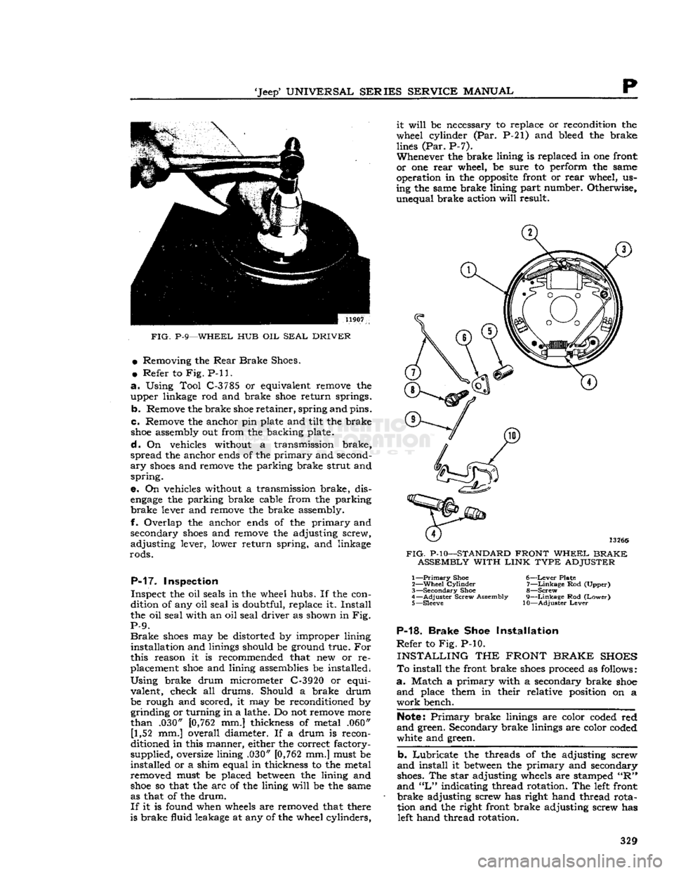
FIG.
P-9—WHEEL HUB OIL
SEAL
DRIVER
•
Removing the
Rear
Brake
Shoes.
•
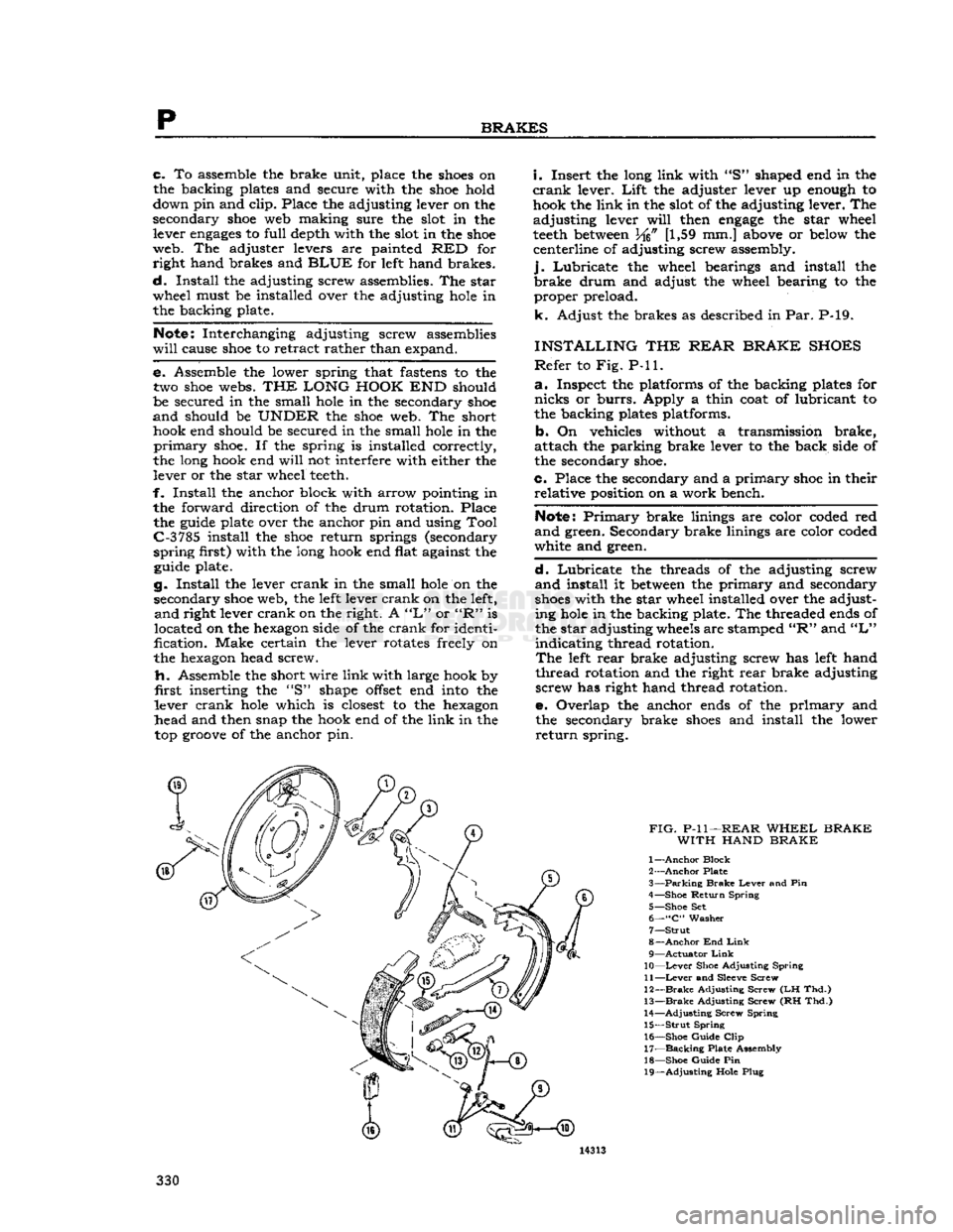
Refer to Fig. P-ll.
a.
Using Tool C-3785 or equivalent remove the
upper linkage rod and brake
shoe
return springs.
b. Remove the brake
shoe
retainer, spring and pins.
c. Remove the anchor pin plate and tilt the brake
shoe
assembly out from the backing plate.
d.
On vehicles without a transmission brake,
spread the anchor
ends
of the primary and second
ary
shoes
and remove the parking brake strut and
spring.
e. On vehicles without a transmission brake, dis
engage
the parking brake cable from the parking
brake
lever and remove the brake assembly.
f. Overlap the anchor
ends
of the primary and
secondary
shoes
and remove the adjusting screw,
adjusting lever, lower return spring, and linkage
rods.
P-17. Inspection
Inspect the oil seals in the wheel hubs. If the con
dition of any oil seal is doubtful, replace it. Install
the oil seal with an oil seal driver as shown in Fig.
P-9.
Brake
shoes
may be distorted by improper lining installation and linings should be ground true. For
this reason it is recommended that new or re
placement
shoe
and lining assemblies be installed.
Using
brake drum micrometer C-3920 or equi
valent, check all drums. Should a brake drum be rough and scored, it may be reconditioned by grinding or turning in a lathe. Do not remove more
than .030"
[0,762
mm.] thickness of metal .060" [1,52 mm.] overall diameter. If a drum is recon
ditioned in this manner, either the correct factory-
supplied, oversize lining .030"
[0,762
mm.] must be
installed or a shim equal in thickness to the metal
removed must be placed
between
the lining and
shoe
so that the arc of the lining
will
be the same
as that of the drum.
If
it is found when
wheels
are removed that there
is brake fluid leakage at any of the wheel cylinders, it
will
be necessary to replace or recondition the
wheel cylinder (Par. P-21) and bleed the brake lines (Par. P-7).
Whenever the brake lining is replaced in one front
or one rear wheel, be sure to perform the same
operation in the
opposite
front or rear wheel, us
ing the same brake lining part number. Otherwise, unequal brake action
will
result.
FIG.
P-10—STANDARD
FRONT
WHEEL
BRAKE
ASSEMBLY
WITH
LINK
TYPE
ADJUSTER 1—
Primary
Shoe
6—Lever
Plate
2—
Wheel
Cylinder
7—Linkage Rod (Upper)
3—
Secondary
Shoe 8—Screw
4—
Adjuster
Screw Assembly 9—Linkage Rod
(Lower)
5— Sleeve 10—Adjuster
Lever
P-18.
Brake
Shoe Installation
Refer
to Fig. P-10.
INSTALLING
THE
FRONT
BRAKE
SHOES
To
install the front brake
shoes
proceed as follows:
a.
Match a primary with a secondary brake
shoe
and
place them in their relative position on a
work
bench.
Note:
Primary
brake linings are color coded red
and
green. Secondary brake linings are color coded
white and green.
b. Lubricate the threads of the adjusting screw
and
install it
between
the primary and secondary
shoes.
The star adjusting
wheels
are stamped "R"
and
"L"
indicating thread rotation. The
left
front
brake
adjusting screw has right hand thread rota
tion and the right front brake adjusting screw has
left
hand thread rotation. 329
Page 330 of 376
p
BRAKES
c. To assemble the brake unit, place the
shoes
on
the backing plates and secure with the
shoe
hold
down pin and clip. Place the adjusting lever on the
secondary
shoe
web making sure the
slot
in the lever
engages
to full depth with the
slot
in the
shoe
web. The adjuster levers are painted RED for right hand brakes and
BLUE
for
left
hand brakes.
d.
Install the adjusting screw assemblies. The star
wheel must be installed over the adjusting
hole
in the backing plate.
Notes
Interchanging adjusting screw assemblies
will
cause
shoe
to retract rather than expand.
e. Assemble the lower spring that
fastens
to the
two
shoe
webs.
THE LONG HOOK
END should
be secured in the small
hole
in the secondary
shoe
and
should be
UNDER
the
shoe
web. The short hook end should be secured in the small
hole
in the
primary
shoe.
If the spring is installed correctly,
the long hook end
will
not interfere with either the lever or the star wheel
teeth.
f. Install the anchor block with arrow pointing in the forward direction of the drum rotation. Place the
guide
plate over the anchor pin and using Tool
C-3
785 install the
shoe
return springs (secondary
spring
first) with the long hook end flat against the
guide
plate.
g. Install the lever crank in the small
hole
on the secondary
shoe
web, the
left
lever crank on the left,
and
right lever crank on the right. A
"L"
or
"R"
is
located on the
hexagon
side of the crank for identi
fication.
Make
certain the lever rotates freely on
the
hexagon
head screw.
fi.
Assemble the short wire link with large hook by
first
inserting the "S" shape
offset
end
into
the
lever crank
hole
which is
closest
to the
hexagon
head and then snap the hook end of the link in the top
groove
of the anchor pin.
i.
Insert the long link with "S" shaped end in the
crank
lever.
Lift
the adjuster lever up
enough
to hook the link in the
slot
of the adjusting lever. The
adjusting lever
will
then
engage
the star wheel
teeth
between
M%
[1,59 mm.]
above
or
below
the centerline of adjusting screw assembly,
j.
Lubricate the wheel bearings and install the
brake
drum and adjust the wheel bearing to the proper preload.
k. Adjust the brakes as described in Par. P-19.
INSTALLING
THE
REAR BRAKE SHOES
Refer
to Fig. P-ll.
a.
Inspect the platforms of the backing plates for
nicks
or
burrs.
Apply a thin coat of lubricant to
the backing plates platforms.
b. On vehicles without a transmission brake,
attach the parking brake lever to the back side of
the secondary
shoe.
c. Place the secondary and a primary
shoe
in their relative position on a work bench.
Note:
Primary
brake linings are color coded red
and
green. Secondary brake linings are color coded
white and green.
d.
Lubricate the threads of the adjusting screw
and
install it
between
the primary and secondary
shoes
with the star wheel installed over the adjusting
hole
in the backing plate. The threaded
ends
of
the star adjusting
wheels
are stamped
"R"
and
"L"
indicating thread rotation.
The
left
rear brake adjusting screw has
left
hand
thread rotation and the right rear brake adjusting screw has right hand thread rotation.
e. Overlap the anchor
ends
of the primary and the secondary brake
shoes
and install the lower
return
spring.