JEEP CJ 1953 Service Manual
Manufacturer: JEEP, Model Year: 1953, Model line: CJ, Model: JEEP CJ 1953Pages: 376, PDF Size: 19.96 MB
Page 361 of 376
'Jeep*
UNIVERSAL
SERIES
SERVICE
MANUAL
U
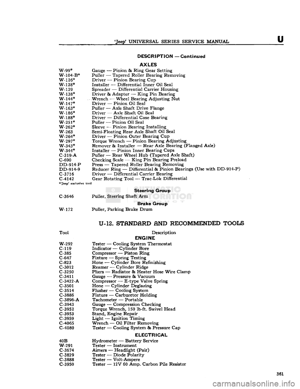
DESCRIPTION
—
Continued
AXLES
W-99* Gauge — Pinion & Ring
Gear
Setting
W-104-B* Puller — Tapered Roller Bearing Removing
W-126* Driver — Pinion Bearing Cup
W-128* Installer — Differential Inner Oil Seal W-129 Spreader — Differential
Carrier
Housing
W-138* Driver & Adapter —
King
Pin Bearing
W-144* Wrench — Wheel Bearing Adjusting Nut W-147* Driver — Pinion Oil Seal W-163* Puller
—-
Axle Shaft Drive Flange
W-186* Driver — Axle Shaft Oil Seal
W-188* Driver — Differential Case Bearing W-251* Puller — Pinion Oil Seal
W-262*
Sleeve
— Pinion Bearing Installing
W-263
Semi-Floating
Rear
Axle Shaft Oil Seal W-264* Driver — Pinion Outer Bearing Cup
W-297* Torque Wrench — Pinion Bearing Adjusting W-343* Remover
85
Installer —
Rear
Axle Bearing (Flanged Axle)
W-344* Installer — Pinion Inner Bearing Cups
C-319-A
Puller —
Rear
Wheel Hub (Tapered Axle Shaft)
C-690 Checking Scale —
King
Pin Bearing Preload DD-914-P Press — Tapered Roller Bearing Removing
DD-914-9 Reducer Ring — Differential & Pinion Bearings (Use with DD-914-P)
C-3
716 Driver — Differential
Carrier
Bearing C-4142
Gear
Rotating Tool —
Trac-Lok
Differential
**Jeep*
exclusive
tool
Steering
Group
C-3646 Puller, Steering Shaft Arm
Brake
Group
W-172 Puller, Parking Brake Drum
U-12.
STflNDfiRD
AND
RECOMMENDED
TOOLS
Tool
Description
ENGINE
W-292
Tester — Cooling
System
Thermostat
C-119 Indicator — Cylinder Bore C-385 Compressor — Piston Ring
C-647 Fixture — Spring Testing
C-823
Hone
— Cylinder Bore Refinishing
C-3012 Reamer — Cylinder Ridge
C-3250 Pliers — Radiator fis Heater
Hose
Wire Clamp
C-3411
Gauge — Pressure & Vacuum
C-3422-A Compressor — E-type Valve Spring
C-3501
Hone
— Cylinder
Deglazing
C-3514
Flusher — Cooling
System
C-3886 Fixture — Carburetor Holding C-3896-A Tachometer — Portable
C-3943 Gauge — Compression Checking
C-3952 Torque Wrench, 150
lb-ft.
Swivel Head C-3953 Stand, Engine Repair
C-3959 Light — Ignition Timing
C-4065 Wrench — Oil Filter Removing
C-4080 Tester — Cooling
System
fig
Pressure Cap
ELECTRICAL
40B Hydrometer — Battery Service
W-291 Tester — Instrument
C-3674
Aimers —
Headlight
(Pair)
C-3829 Tester —
Diode
Polarity
C-3888 Tester — Volt-Ampere C-3950 Tester — 12V 60 Amp. Carbon Pile Resistor 361
Page 362 of 376
u
MISCELLANEOUS
U-12.
STANDARD
AND
RECOMMENDED TOOLS
(Continued)
Tool
Description
CLUTCH
W-296 Fixture — Adjusting
TRANSMISSION
C-3201
- A
Lo-Jack
— Floor Type
AXLE
C-637 Puller — Axle Shaft & Oil Seal
STEERING
DD-428 Gauge — Camber & Caster
DD-435 Turntables — Wheel Alignment C-3479 Gauge & Scribe — Toe-in Checking
BRAKES
C-416 Clamps — Brake Cylinder Retaining C-3080 Hone — Brake Cylinder
C-3496-B Bleeder — Hydraulic Pressure Type C-3785 Remover & Installer — Brake Return Spring
C-3920 Micrometer — Brake Drum Checking
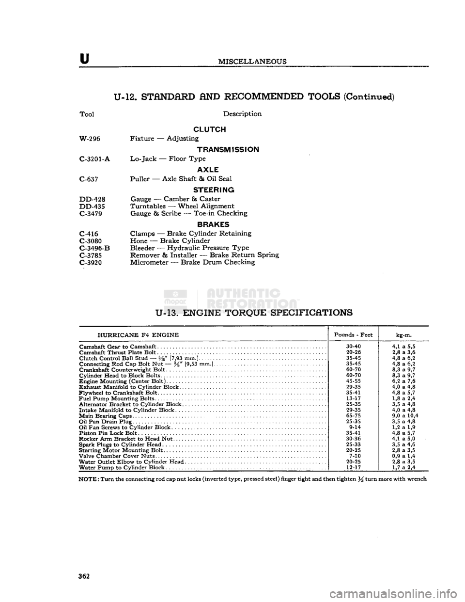
U-13.
ENGINE TORQUE SPECIFICATIONS HURRICANE
F4
ENGINE
Pounds - Feet
kg-m.
30-40
4,1
a
5,5
Camshaft
Thrust Plate Bolt
20-26
2,8
a
3,6
Clutch
Control
Ball
Stud — [7,93 mm.]
35-45
4,8
a
6,2
Connecting Rod Cap Bolt Nut — y8" [9,53 mm.|
35-45
4,8
a
6,2
60-70
8,3
a
9,7
Cylinder
Head to Block Bolts
60-70
8,3
a
9,7
45-55
6,2
a
7,6
29-35
4,0
a
4,8
Flywheel
to Crankshaft Bolt. 35-41
4,8
a
5,7
Fuel
Pump Mounting Bolts 13-17 1,8
a
2,4
Alternator Bracket to Cylinder Block.
25-35
3,5
a
4,8
29-35
4,0
a
4,8
Main
Bearing
Caps.
.
65-75
9,0
a
10,4
Oil
Pan
Drain
Plug
25-35
3,5
a
4,8
9-14 1,2
a
1,9
Piston Pin
Lock
Bolt 35-41
4,8
a
5,7
30-36
4,1
a
5,0
Spark
Plugs to Cylinder Head
25-33
3,5
a
4,6
Starting Motor Mounting Bolt.
20-25
2,8
a
3,5
7-10 0,9
a
1,4
Water
Outlet Elbow to Cylinder Head
20-25
2,8
a
3,5
Water
Pump to Cylinder Block 12-17
1,7
a
2,4
NOTE:
Turn
the connecting rod cap nut locks (inverted type, pressed
steel)
finger
tight
and then
tighten
% turn more with wrench
362
Page 363 of 376
'Jeep*
UNIVERSAL SERIES
SERVICE
MANUAL
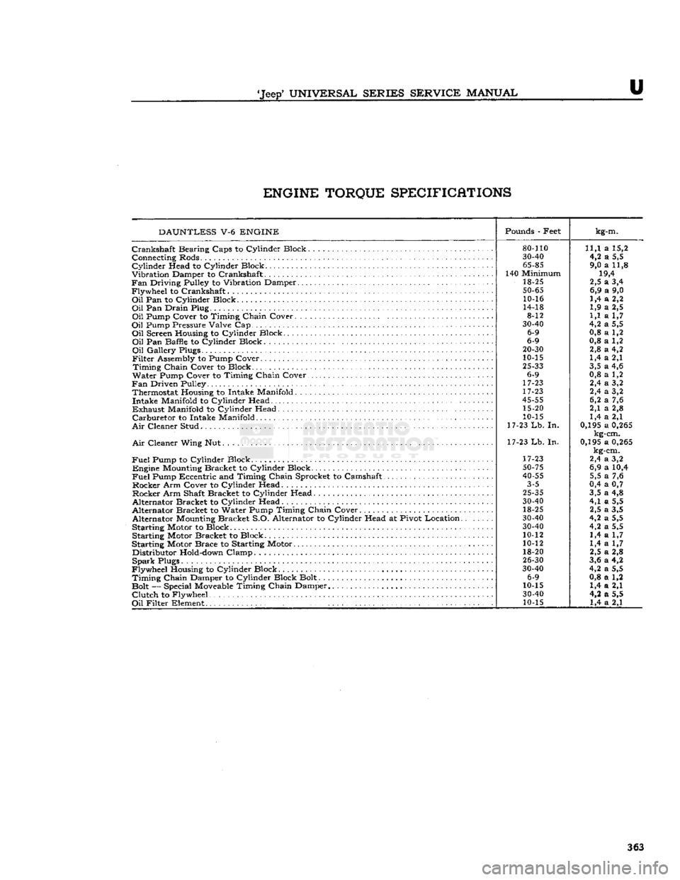
U ENGINE TORQUE SPECIFICATIONS
DAUNTLESS
V-6
ENGINE
Pounds
- Feet
kg-m.
80-110
11,1 a 15,2
30-40
4,2 a 5,5
65-85
9,0 a 11,8
140 Minimum 19,4
18-25 2,5 a 3,4
50-65
6,9 a 9,0
10-16 1,4 a 2,2
14-18 1,9 a 2,5
8-12 1,1 a 1,7
30-40
4,2 a 5,5
6-9 0,8 a 1,2
6-9 0,8 a 1,2
20-30
2,8 a 4,2
10-15 1,4 a 2,1
25-33
3,5 a 4,6
6-9 0,8 a 1,2
17-23 2,4 a 3,2
17-23 2,4 a 3,2
45-55
6,2 a 7,6
15-20 2,1 a 2,8
10-15 1,4 a 2,1
17-23
Lb.
In. 0,195 a
0,265
kg-cm.
17-23 Lb. In. 0,195 a
0,265
kg-cm.
17-23 2,4 a 3,2
50-75
6,9 a 10,4
40-55
5,5 a 7,6
3-5 0,4 a 0,7
25-35
3,5 a 4,8
30-40
4,1 a 5,5
18-25 2,5 a 3,5
30-40
4,2 a 5,5
30-40
4,2 a 5,5
10-12 1,4 a 1,7
10-12 1,4 a 1,7
18-20 2,5 a 2,8
26-30
3,6 a 4,2
30-40
4,2 a 5,5
6-9 0,8 a 1,2
10-15 1,4 a 2,1
30-40
4,2 a 5,5
10-15 1,4 a 2,1
Crankshaft
Bearing Caps to Cylinder Block.
Connecting Rods.
Cylinder
Head to Cylinder Block
Vibration Damper to Crankshaft
Fan
Driving Pulley to Vibration Damper
Flywheel to Crankshaft
Oil
Pan to Cylinder Block
Oil
Pan Drain Plug
Oil
Pump Cover to Timing Chain Cover. . .
Oil
Pump Pressure Valve Cap
Oil
Screen Housing to Cylinder Block
Oil
Pan Baffle to Cylinder Block
Oil
Gallery Plugs.
Filter
Assembly to Pump Cover
Timing
Chain Cover to Block
Water Pump Cover to Timing Chain Cover.
Fan
Driven Pulley Thermostat Housing to Intake Manifold. . . Intake Manifold to Cylinder Head
Exhaust
Manifold to Cylinder Head
Carburetor
to Intake Manifold
Air
Cleaner Stud
Air
Cleaner Wing Nut.
Fuel
Pump to Cylinder Block . . Engine
Mounting
Bracket to Cylinder Block
Fuel
Pump Eccentric and Timing Chain Sprocket to Camshaft
Rocker Arm Cover to Cylinder Head Rocker Arm Shaft Bracket to Cylinder Head
Alternator Bracket to Cylinder Head
Alternator Bracket to Water Pump Timing Chain Cover Alternator
Mounting
Bracket S.O. Alternator to Cylinder Head at Pivot Location.
Starting Motor to Block Starting Motor Bracket to Block
Starting Motor Brace to Starting Motor Distributor
Hold-down
Clamp
Spark
Plugs
Flywheel Housing to Cylinder Block
Timing
Chain Damper to Cylinder Block Bolt.
Bolt — Special
Moveable
Timing Chain Damper
Clutch
to Flywheel
Oil
Filter Element .' 363
Page 364 of 376
u
MISCELLANEOUS
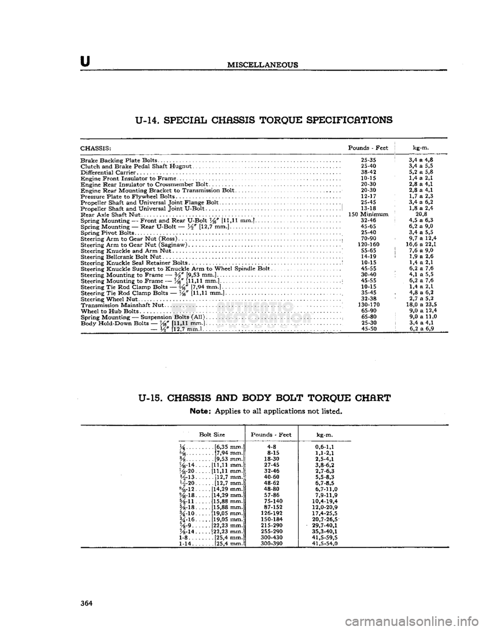
U-14.
SPECIAL
CHASSIS
TORQUE
SPECIFICATIONS
CHASSIS:
Pounds
-
Feet
j kg-m.
Brake
Backing Plate Bolts.
25-35 ! 3,4 a 4,8
Clutch
and
Brake Pedal Shaft Hugnut
25-40 3,4 a 5,5
Differential
Carrier
38-42 5,2 a 5,8
Engine
Front Insulator
to
Frame.
10-15 1,4 a 2,1
Engine
Rear
Insulator
to
Crossmember Bolt.
. . ... 20-30 2,8 a 4,1
Engine
Rear
Mounting Bracket
to
Transmission Bolt.
20-30 2,8 a 4,1
Pressure
Plate
to
Flywheel Bolts
12-17 1,7 a 2,3
Propeller Shaft
and
Universal Joint Flange Bolt
25-45 3,4 a 6,2
Propeller Shaft
and
Universal Joint U-Bolt
1 13-18 : 1,8 a 2,4
Rear
Axle Shaft
Nut 150
Minimum
; 20,8
Spring
Mounting
—
Front
and
Rear
U-Bolt
V^n [11,11 mm.] 32-46 i 4,5 a 6,3
Spring
Mounting —-
Rear
U-Bolt
— [12,7 mm.] 45-65 6,2 a 9,0
Spring
Pivot Bolts
." 25-40 3,4 a 5,5
Steering Arm
to
Gear
Nut
(Ross)
..
i
70-90 9,7 a 12,4
Steering Arm
to
Gear
Nut
(Saginaw)
' 120-160 16,6 a 22,1
Steering Knuckle
and
Arm Nut..........
55-65 j 7,6 a 9,0
Steering Bellcrank Bolt
Nut 14-19 < 1,9 a 2,6
Steering Knuckle Seal Retainer Bolts
S 10-15 1,4 a 2,1
Steering Knuckle Support
to
Knuckle Arm
to
Wheel Spindle Bolt
45-55 , 6,2 a 7,6
Steering Mounting
to
Frame
—
Y%
[9,53 mm.] 30-40 '• 4,1 a 5,5
Steering Mounting
to
Frame
— W [11,11
mm.]...
i 45-55 6,2 a 7,6
Steering
Tie Rod
Clamp Bolts
— [7,94 mm.] 10-15 1,4 a 2,1
Steering
Tie Rod
Clamp Bolts
— Ke" [U,H mm.] ; 35-45 , 4,8 a 6,2
Steering Wheel
Nut 32-38 1 2,7 a 5,2
Transmission
Mainshaft
Nut 130-170 18,0 a 23,5
Wheel
to Hub
Bolts
65-90 9,0 a 12,4
Spring
Mounting
—
Suspension Bolts
(All) , 65-80 9,0 a 11,0
Body Hold-Down Bolts
— W [11,11 mm.} 25-30 i 3,4 a 4,1
—
W [12,7 mm.l , . . 45-50 I 6,2 a 6,9
U-15.
CHASSIS
AND
BODY
BOLT
TORQUE
CHART
Note:
Applies to all applications not listed.
Bolt Size Pounds
-
Feet
kg-m.
.....
[6,35 mm.] 4-8
0,6-1,1
[7,94 mm.] 8-15
1,1-2,1
[9,53 mm.] 18-30
2,5-4,1
"Mrl4.
[11,11 mm.]
27-45
3,8-6,2
116-20. [11,11 mm.] 32-46
2,7-6,3
M-13.
[12,7
mm.]
40-60
5,5-8,3
H-20
[12,7
mm.]
48-62
6,7-8,5
%-12.
[14,29 mm.]
48-80
6,7-11,0
%-lB.
[14,29 mm.]
57-86
7,9-11,9
5A-n. [15,88 mm.]
75-140
10,4-19,4
[15,88 mm.] 87-152
12,0-20,9
U-io.
[19,05 mm.]
126-192
17,4-25,5
§4-16.
[19,05 mm.]
150-184
20,7-26,5
Vs'9..
[22,23 mm.]
215-290
29,7-40,1
K-14.
[22,23 mm.]
255-290
35,3-40,1
1-8 [25,4 mm.] 300-430
41,5-59,5
1-14. . [25,4 mm.]
300-390 41,5-54,0 364
Page 365 of 376
u
MISCELLANEOUS
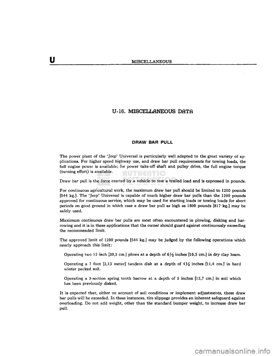
U-16. MISCELLtflNEOUS DATA
DRAW
BAR
PULL
The
power plant of the 'Jeep* Universal is particularly well adapted to the great variety of ap
plications. For higher speed highway use, and draw bar
pull
requirements for towing loads, the
full
engine
power is available; for power take-off shaft and pulley drive, the
full
engine
torque
(turning
effort) is available.
Draw
bar
pull
is the force exerted by a vehicle to tow a trailed load and is expressed in pounds.
For
continuous
agricultural
work, the maximum draw bar
pull
should be limited to 1200 pounds [544 kg.]. The 'Jeep' Universal is capable of much higher draw bar pulls than the 1200 pounds
approved for continuous service, which may be used for starting loads or towing loads for short
periods on
good
ground in which case a draw bar
pull
as high as 1800 pounds [817 kg.] may be
safely used.
Maximum
continuous draw bar pulls are most
often
encountered in plowing, disking and
har
rowing
and it is in
these
applications that the owner should guard against continuously exceeding
the recommended limit.
The
approved limit of 1200 pounds [544 kg.] may be judged by the following operations which
nearly
approach this limit:
Operating
two 12 inch [30,5 cm.] plows at a depth of 6)4 inches [16,5 cm.] in dry clay loam.
Operating
a 7
foot
[2,13 meter] tandem disk at a depth of 4j^ inches [11,4 cm.] in
hard
winter
packed soil.
Operating
a 3-section spring
tooth
harrow at a depth of 5 inches [12,7 cm.] in soil which
has been previously disked.
It
is expected that, either on account of soil conditions or implement adjustments,
these
draw
bar
pulls
will
be exceeded. In
these
instances, tire slippage provides an inherent safeguard against
overloading. Do not add weight, other than the standard bumper weight, to increase draw bar
pull.
Page 366 of 376
u
MISCELLANEOUS
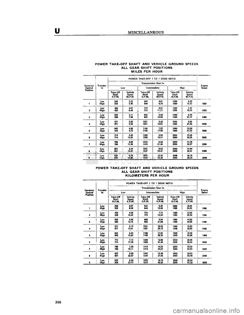
POWER TAKE-OFF SHAFT
AND
VEHICLE GROUND SPEEDS
ALL
GEAR SHIFT POSITIONS MILES
PER
HOUR
POWER TAKE-OFF
1 TO 1
GEAR RATIO
Governor Control
Position Transfer
In
Transmission Gear
In
Engine Speed
Governor
Control
Position Transfer
In Low
Intermediate
High Engine
Speed
Governor
Control
Position Take-Off
Shaft
R.P.M.
Vehicle
Speed
M.P.H. Take-Off
Shaft
R.P.M.
Vehicle
Speed
M.P.H. Take-Off
Shaft
R.P.M.
Vehicle
Speed
M.P.H.
1 Low
High
358
358 2.22
5.40 644
644
4.01
9.75 1000
1000 6.22
15.13 1000
2 Low
High
428
428 2.67
6.48 773
773 4.81
11.71 1200
1200
7.47
18.15 1200
3 Low
High
500
500 3.11
7.56 902
902 5.62
13.66 1400
1400 8.72
21.17 1400
4 Low
High
571
571 3.56
8.65
1031
1031
6.42
15.61 1600
1600 9.96
24.20
1600
5 Low
High
643
643 4.00
9.73 1160
1160 7.22
17.56 1800
1800 12.08
27.22
1800
e Low
High
714
714 4.44
10.81 1289
1289
8.02
19.51
2000
2000
12.45
30.25 2000
7 Low
High
786
788 489
11.89 1418
1418 8.83
21.48
2200
2200
13.70
33.27
2200
8 Low
High
857
857 5.34
12.97 1547
1547 9.63
23.41
2400
2400
14.84
36.31
2400
9 Low
High
928
929 5.78
14.05 1875
1675
10.43
25.36 2600
2600
16.19
39.33 2600
POWER TAKE-OFF SHAFT
AND
VEHICLE GROUND SPEEDS
ALL
GEAR SHIFT POSITIONS KILOMETERS
PER
HOUR
Governor Control
Position Transfer
In
POWER TAKE-OFF
1 TO 1
GEAR RATIO
Engine Speed
Governor
Control
Position Transfer
In
Transmission Gear
In
Engine
Speed
Governor
Control
Position Transfer
In Li
)W
Intern lediate
H" gh
Engine
Speed
Governor
Control
Position Transfer
In
Take-Off Shaft
R.P.M.
Vehicle
Speed
K.P.M.
Take-Off
Shaft
R.P.M.
Vehicle
Speed
K.P.M.
Take-Off
Shaft
R.P.M.
Vehicle
Speed
K.P.M.
1 Low
High
358
358 3.57
8.68 844
644
6.45
15.68 1000
1000 18.00
24.35
1000
2 Low
High
428
428 4.29
10.43 773
773 7.73
18.84 1200
1200 12.02
29.20
1200
3 Low
High
500
500 5.00
12.16 902
902 9.04
21.98 1400
1400 14.02
34.05
1400
4 Low
High
571
571 5.72
13.91 1031
1031
10.33
25.12
1600
1600 16.03
38.93
1600
5 Low
High
643
843 6.44
15.65 1160
1180
11.61
28.25
1800
1800 19.43
43.80
1806
6 Low
High
714
714 7.15
17.39 1289
1289 12.90
31.40
2000
2000 20.00
48.65 2000
7 Low
High
786
786
7.86
19.11 1418
1418 14.20
34.53
2200
2200 22.02
53.53
2200
8 Low
High
857
857 8.59
20.87
1547
1547 15.48
37.66
2400
2400 24.03
58.40
2400
9 Low
High
929
929 9.30
22.60
1675
1675 16.78
40.80
2600
2600 26.04
63.28 2600
366
Page 367 of 376
'Jeep9
UNIVERSAL
SERIES SERVICE
MANUAL
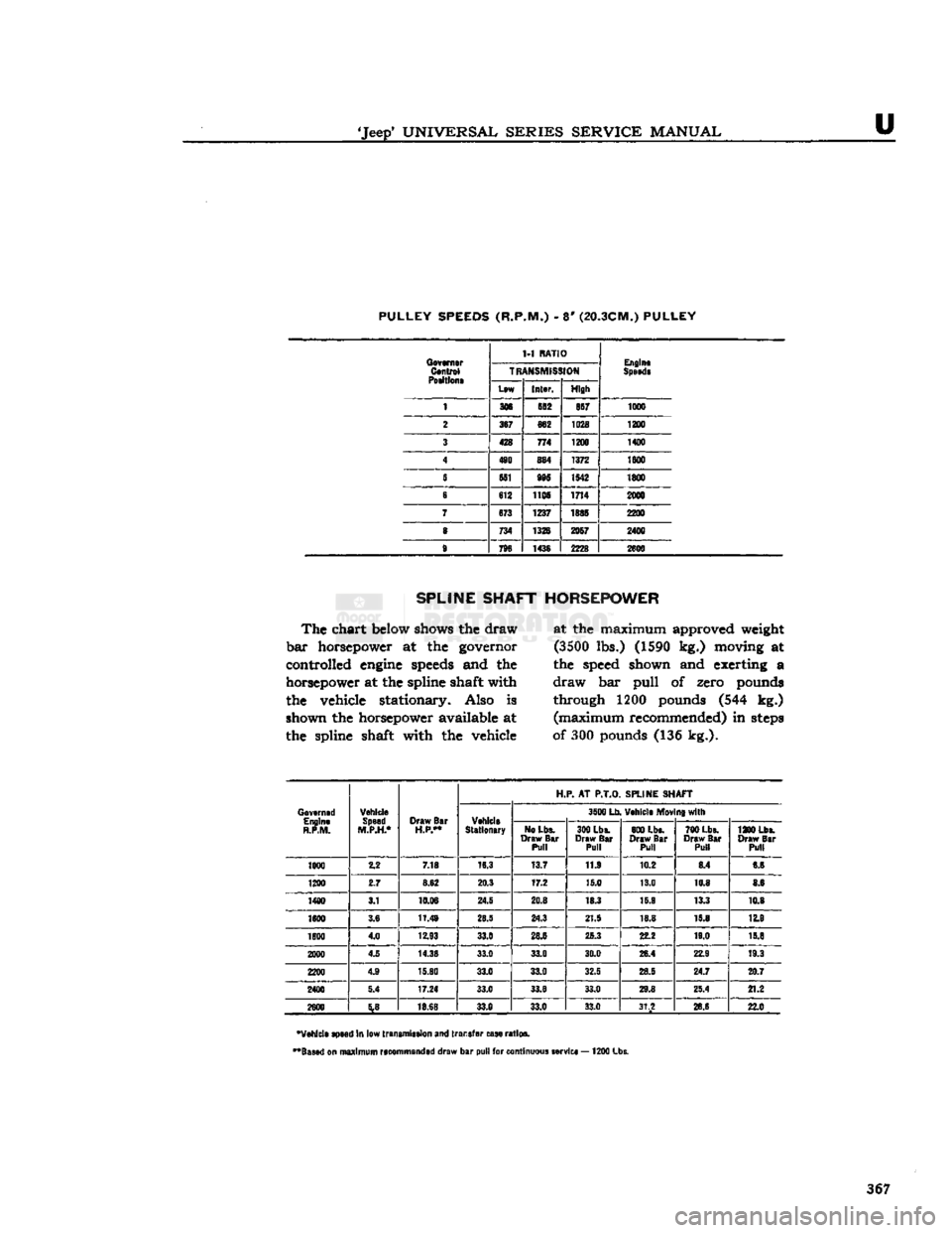
U PULLEY SPEEDS (R.P.M.)
- 8'
(20.3CM.) PULLEY
Governor
Control
Poeltlone
1-1
RATIO
Engine
Speede
Governor
Control
Poeltlone
TR
ANSMISS
HON
Engine
Speede
Governor
Control
Poeltlone
Lew
Inter.
High
1 306
682
857 1000
2
367
662
1028 1200
3
428
774 1200 1400
4
480 884
1372 1600
S
5S1 985 1542
1800
e 612 1105
1714 2000
7 673
1237 1885 2200
8
734 1326
2057 2400
9
796 1436
2228 2600
SPLINE SHAFT HORSEPOWER
The
chart
below shows
the
draw
bar
horsepower
at the
governor
controlled
engine
speeds
and
the
horsepower
at
the
spline shaft with
the vehicle stationary. Also
is
shown
the
horsepower available
at
the spline shaft with
the
vehicle at
the
maximum approved weight
(3500
lbs.) (1590
kg.)
moving
at
the speed shown
and
exerting
a
draw
bar
pull
of
zero pounds through
1200
pounds
(544 kg.)
(maximum
recommended)
in
steps
of 300 pounds
(136
kg.).
Governed Engine
R.P.M. Vehicle
Speed
M.P.H.* Draw
Bar
H.P**
H.P.
AT
P.T.O.
SPLINE SHAFT
Governed Engine
R.P.M. Vehicle
Speed
M.P.H.* Draw
Bar
H.P**
Vehicle
Stationary 3600
Lb
Vehicle
Mov
ng with
Governed
Engine
R.P.M. Vehicle
Speed
M.P.H.* Draw
Bar
H.P**
Vehicle
Stationary
No
Lbs.
Draw
Bar
Pull 300 Lbs.
Draw
Bar
Pull 800 Lbs.
Draw
Bar
Pull 700
Lbs.
Draw
Bar
Pull 1200
Lbs.
Draw
Bar
Pull
1000 2.2
7.18 16.3
13.7 11.9
10.2
8.4 6.6
1200 2.7 8.62 20.3
17.2
15.0 13.0
10.8 8.6
1400 3.1 10.06
24.5 20.8 18.3
15.9 13.3 10.8
1600 3.6
11.49 28.5 24.3 21.5
18.8 15.8 12.9
1800 4.0
12.93 33.0
28.6 25.3
22.2 19.0
15.8
2000 4.5
14.38 33.0 33.0
30.0 26.4 22.9
19.3
2200 4.9
15.80
33.0 33.0 32.5
28.5
24.7 20.7
2400 5.4 17.24
33.0 33.0 33.0 29.8 25.4
21.2
2600
%B
18.68 33.0
33.0 33.0
31.2 26.6
22.0
'Vehicle speed
in
low transmission
and
transfer case ratios.
••Based
on
maximum recommended draw
bar
pull
for
continuous service
—
1200
Lbs. 367
Page 368 of 376
MISCELLANEOUS
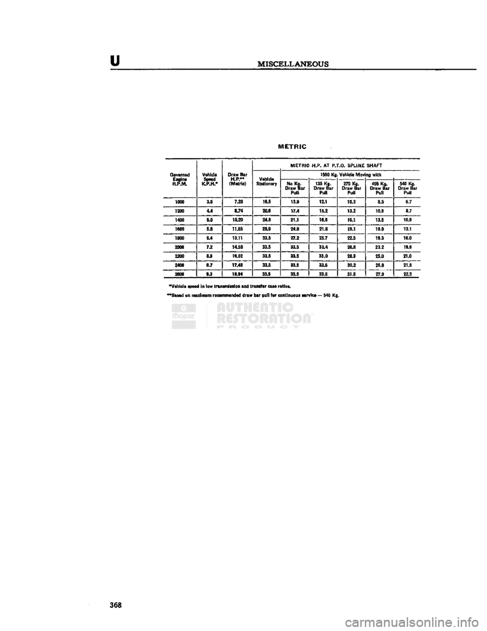
METRIC
Governed Engine
R.P.M. Vehicle
Speed
K.P.H.* Draw Bar
H.P.**
(Metric) METRIC H.P. AT
P.T.O.
SPLINE SHAFT
Governed Engine
R.P.M. Vehicle
Speed
K.P.H.* Draw Bar
H.P.**
(Metric) Vehicle
Stationary 1590 Kg
Vehicle Mov ng with
Governed
Engine
R.P.M. Vehicle
Speed
K.P.H.* Draw Bar
H.P.**
(Metric) Vehicle
Stationary No Kg.
Draw Bar Pull 135 Kg.
Draw Bar Pull 270 Kg.
Draw Bar Pull 405 Kg.
Draw Bar Pull 540 Kg.
Draw Bar Pull
1000 S.§
7.28 16J
13.9 12.1
10.3 8.5 6.7
1200 44 8.74 20.6
17.4 15.2
13.2 10.9 8.7
1400 S.0
10.20
248
21.1 18.6
16.1 13.5 10.9
1800 5.8 11.65 28.9
24.6 21.8 19.1
18.8 13.1
1800 6.4 13.11 33.5
27.2 25.7
22.5 19.3 16.0
2000 7.2 14.58
33.5 33.5 30.4
26.8 23.2 19.6
1200 8.9
16.02
33J 33.5
33.0 28.9
25.0 21.0
2400 8.7 17.48 33.5
33.5 33.5
30.2 25.8 21.5
2600 9.3
18.94 33J 33.5 33 5
31.6 270 22.3
"Vehicle speed in low transmission and transfer case ratios.
••Based
on maximum recommended draw bar pull for continuous service — 540 Kg. 368
Page 369 of 376
'Jeep'
UNIVERSAL
SERIES SERVICE
MANUAL
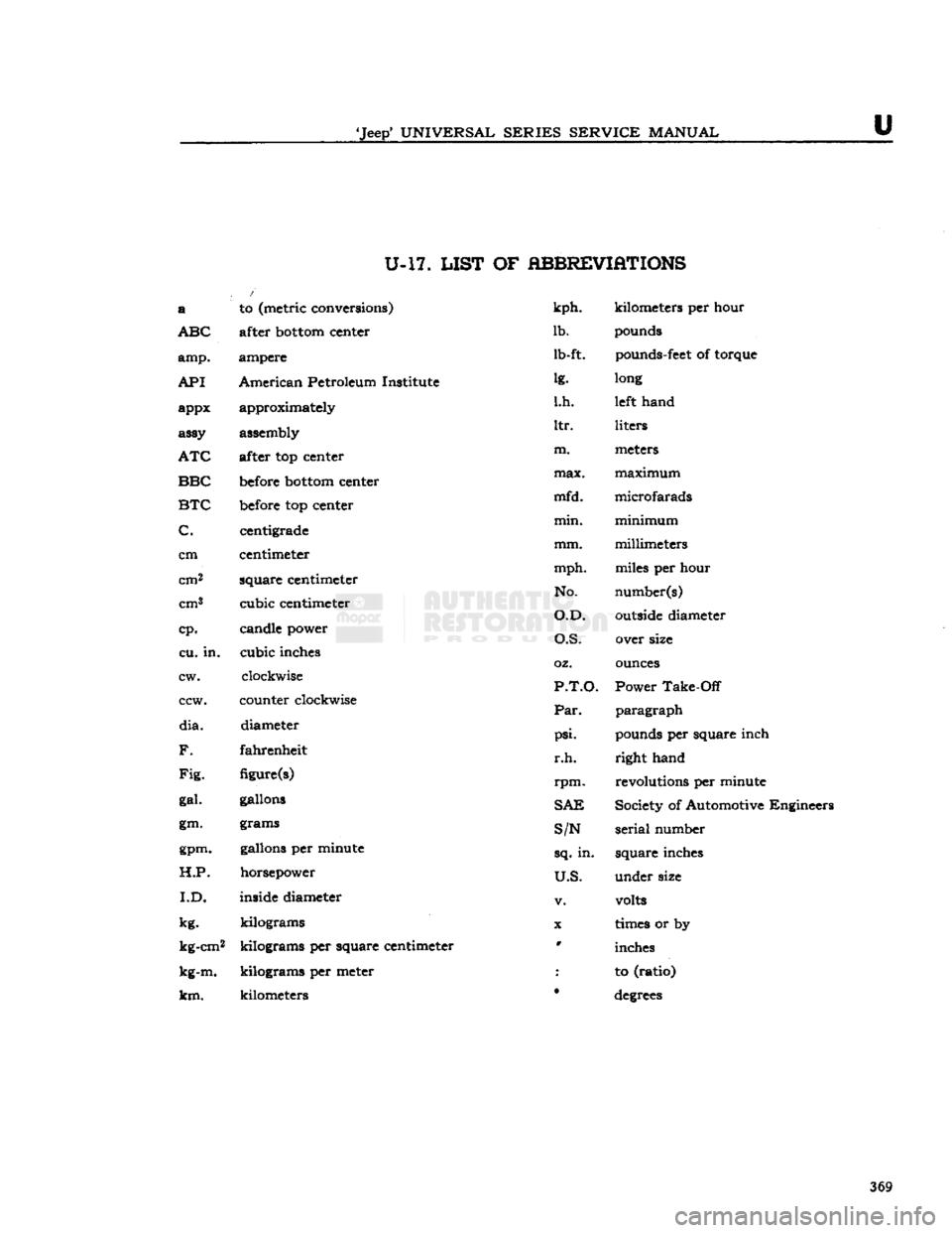
U-17.
LIST
OF
ABBREVIATIONS
/
a
to (metric conversions)
kph.
kilometers per hour
ABC
after
bottom
center
lb.
pounds
amp.
ampere lb-ft.
pounds-feet
of torque
API
American
Petroleum Institute
lg.
long
appx approximately
l.h.
left
hand
assy assembly
ltr.
liters
ATC
after top center
m.
meters
BBC
before
bottom
center
max.
maximum
BTC
before
top center
mfd.
microfarads
C.
centigrade
min.
minimum
C.
centigrade
centimeter
mm.
millimeters
cm
centimeter
cm2
square
centimeter
mph.
miles per hour
square
centimeter
No.
number(s)
outside
diameter
cm3
cubic
centimeter
O.D.
number(s)
outside
diameter
cp.
candle power
O.S.
cp.
O.S.
over size
cu.
in.
cubic
inches
oz.
ounces
cw.
clockwise
cw.
clockwise
P.T.O.
Power
Take-Off
CCW.
counter clockwise
paragraph
CCW.
counter clockwise
Par.
paragraph
dia.
diameter
psi.
pounds per square inch
F.
fahrenheit
r.h.
right
hand
Fig.
figure(s)
rpm.
revolutions per minute
gal.
gallons
SAE
Society of Automotive Engineers
gm. grams
S/N
serial
number
gpm. gallons per minute
sq.
in.
square
inches
H.P.
horsepower
U.S.
under
size
I.D.
inside diameter
v.
volts
kg.
kilograms
X
times
or by
kg-cm2
kilograms
per square centimeter w
inches
kg-m.
kilograms
per meter
:
to (ratio)
km.
kilometers
•
degrees
369
Page 370 of 376
