engine JEEP RENEGADE 2018 Owner handbook (in English)
[x] Cancel search | Manufacturer: JEEP, Model Year: 2018, Model line: RENEGADE, Model: JEEP RENEGADE 2018Pages: 356, PDF Size: 6.11 MB
Page 166 of 356
IMPORTANT It is dangerous to leave
the device activated when it is not
used. There is a risk of inadvertently
activating it and losing control of the
vehicle due to unexpected excessive
speed.
Deactivation
With the device active, to deactivate it
press and release the
button. The
display will show a dedicated message.
SETTING THE DESIRED SPEED
The device can be set only with speeds
above 30 km/h (or 20 mph for markets
with instrument panels giving mph) and
under 160 km/h (or 100 mph for
markets with instrument panels
giving mph).
When the vehicle reaches the desired
speed, press and release the button SET
+ or SET to set the speed to the current
speed. The display will show the set
speed. Then take your foot off the
accelerator pedal.
The system cannot be set
when pressing the brake pedal;when the brakes are overheated;when the electric parking brake is
engaged;
when the shift lever is in the P (park),
R (reverse) or N (neutral) positions
(versions with automatic transmission orautomatic transmission with double
clutch);
when the shift lever is in the R
(reverse), neutral or in 1st (first gear
engaged) positions (versions with manual
transmission);
when the clutch is pressed (versions
with manual transmission);
when the engine speed exceeds a
maximum threshold (versions with
manual transmission and versions with
automatic transmission/automatic
transmission with double clutch) or goes
below a minimum threshold (only
versions with manual transmission);
when the car speed is not within the
settable speed range;
when the ESC (or ABS or other
stability control systems) are operating or
have just operated;
when the ESC system is off;during automatic braking by the
Forward Collision Warning Plus system
(where provided);
when the Speed Limiter is active;when the electronic Cruise Control is
active;
in case of failure of the device;when the engine is off;in case of obstruction of the radar
sensor (in this case the bumper area
where it is located must be cleaned).
IMPORTANT The device does not
deactivate on reaching speeds higher
than those that can be set (160 km/h
or 100 mph for instrument panel set
to mph) with the accelerator pedal
pressed. In these conditions, the
device may not work correctly and it is
advisable to deactivate it.
CHANGING SPEED
Speed increase
After having set the device, the stored
speed can be stored by holding the SET
+ button pressed.
Press the SET + button once: the set
speed will increase by 1 km/h (or by
1 mph when the measurement unit is set
to mph). Each touch of the button once
will increase the speed by 1 km/h (or by
1 mph, the latter for instrument panels
set to miles per hour).
Hold the SET + button pressed: the set
speed will increase in 10 km/h steps (or
in 5 mph steps when the measurement
unit is set to mph) until the button is
released. The set speed increase is
shown on the display.
Decreasing speed
After having set the device, the stored
speed can be reduced by holding the
SET – button pressed.
164
STARTING AND DRIVING
Page 174 of 356
ACTIVATION/DEACTIVATION
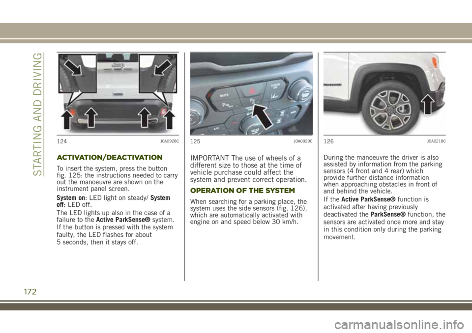
To insert the system, press the button
fig. 125: the instructions needed to carry
out the manoeuvre are shown on the
instrument panel screen.
System on: LED light on steady/System
off: LED off.
The LED lights up also in the case of a
failure to theActive ParkSense®system.
If the button is pressed with the system
faulty, the LED flashes for about
5 seconds, then it stays off.
IMPORTANT The use of wheels of a
different size to those at the time of
vehicle purchase could affect the
system and prevent correct operation.
OPERATION OF THE SYSTEM
When searching for a parking place, the
system uses the side sensors (fig. 126),
which are automatically activated with
engine on and speed below 30 km/h.During the manoeuvre the driver is also
assisted by information from the parking
sensors (4 front and 4 rear) which
provide further distance information
when approaching obstacles in front of
and behind the vehicle.
If theActive ParkSense®function is
activated after having previously
deactivated theParkSense®function, the
sensors are activated once more and stay
in this condition only during the parking
movement.
124J0A0928C125J0A0929C126J0A0218C
172
STARTING AND DRIVING
Page 180 of 356
LANESENSE SYSTEM (lane
crossing warning)
DESCRIPTION
68) 69) 70) 71) 72) 73)
The LaneSense system makes use of a
camera located on the windscreen to
detect the lane limits and calculate the
position of the vehicle within such limits,
in order to make sure that it remains
inside the lane.
When both limits of the lane are detected
and the vehicle crosses one of them
without the awareness of the driver
(direction indicator off), the system
provides a tactile warning by applying
torque to the steering wheel, signalling
the driver that he must take an action to
remain into the lane.
If the vehicle continues going beyond the
line of the lane without any intervention
from the driver, the
warning light (or
the corresponding graphic icon on the
reconfigurable multifunction display) will
be displayed on the instrument panel to
urge the driver to bring the vehicle back
into the limits of the lane.
IMPORTANT The system monitors the
presence of the driver's hands on the
steering wheel. If they are not detected,the system emits an acoustic signal and
deactivates until it is reactivated by
pressing the dedicated button.
When one limit of the lane is detected
and the vehicle crosses it (direction
indicator off), warning light
(or the
icon on the reconfigurable multifunction
display) will be displayed on the
instrument panel to urge the driver to
bring the vehicle back into the lane. In
this case, the tactile warning (torque on
the steering wheel) is not provided.
SYSTEM ON/OFF
When the engine is started the system is
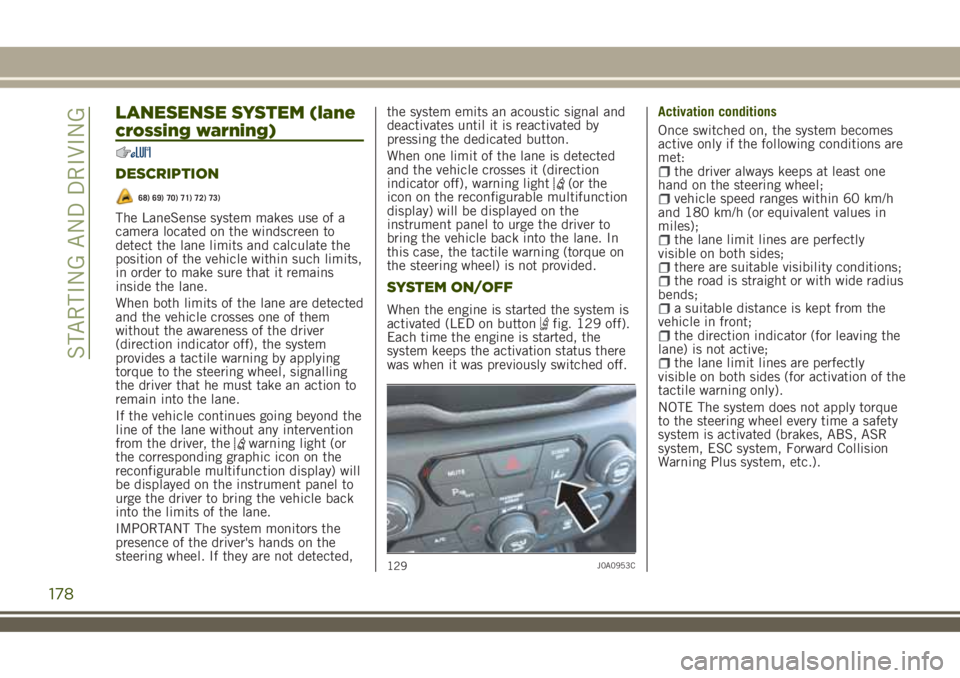
activated (LED on buttonfig. 129 off).
Each time the engine is started, the
system keeps the activation status there
was when it was previously switched off.Activation conditions
Once switched on, the system becomes
active only if the following conditions are
met:
the driver always keeps at least one
hand on the steering wheel;
vehicle speed ranges within 60 km/h
and 180 km/h (or equivalent values in
miles);
the lane limit lines are perfectly
visible on both sides;
there are suitable visibility conditions;the road is straight or with wide radius
bends;
a suitable distance is kept from the
vehicle in front;
the direction indicator (for leaving the
lane) is not active;
the lane limit lines are perfectly
visible on both sides (for activation of the
tactile warning only).
NOTE The system does not apply torque
to the steering wheel every time a safety
system is activated (brakes, ABS, ASR
system, ESC system, Forward Collision
Warning Plus system, etc.).
129J0A0953C
178
STARTING AND DRIVING
Page 183 of 356
REFUELLING THE VEHICLE
Always stop the engine before refuelling.
145) 146) 147)
PETROL ENGINES
Only use unleaded petrol with a number
of octanes (R.O.N.) not lower than 95
(EN228 specification).
DIESEL ENGINES
75)
Only use Diesel for motor vehicles
(EN590 specification).
When using or parking the vehicle for a
long time in the mountains or cold areas,
it is advisable to refuel using locally
available diesel. In this case, it is also
advisable to keep the tank over 50% full.
PETROL/LPG ENGINES
LPG FILLER CAP
The gas filler is located next to the petrol
filler cap. It has a check valve, located in
the filler body itself.
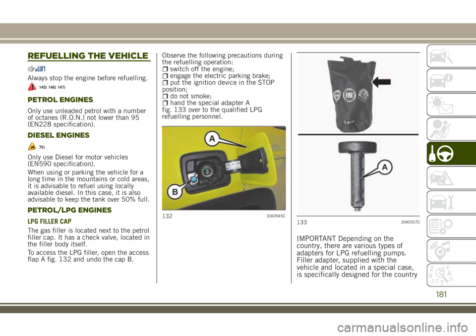
To access the LPG filler, open the access
flap A fig. 132 and undo the cap B.Observe the following precautions during
the refuelling operation:
switch off the engine;engage the electric parking brake;put the ignition device in the STOP
position;
do not smoke;hand the special adapter A
fig. 133 over to the qualified LPG
refuelling personnel.
IMPORTANT Depending on the
country, there are various types of
adapters for LPG refuelling pumps.
Filler adapter, supplied with the
vehicle and located in a special case,
is specifically designed for the country
132J0A0945C133J0A0507C
181
Page 186 of 356
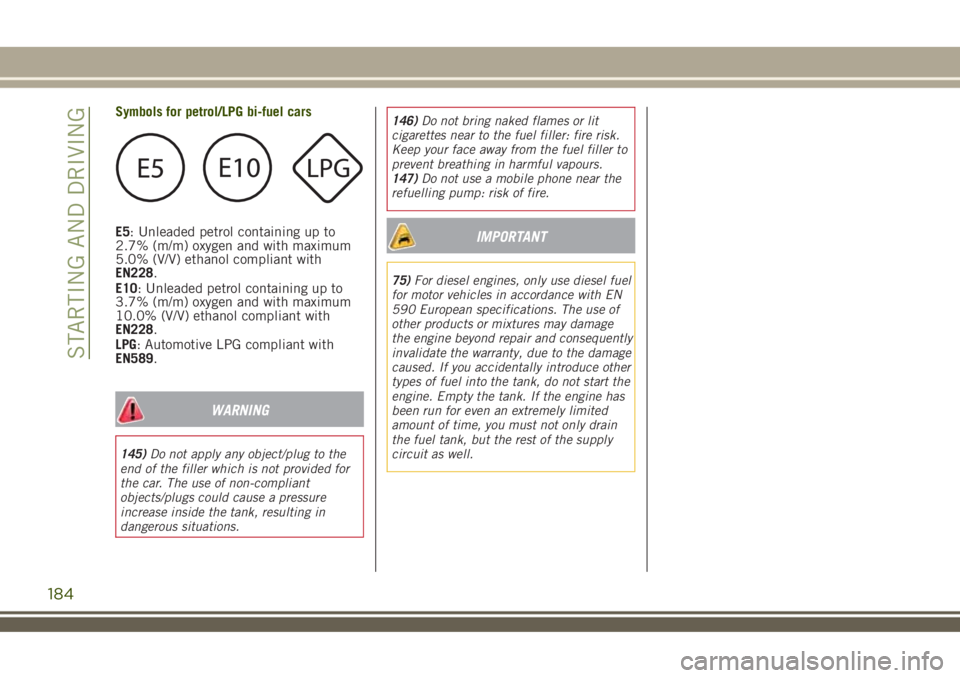
Symbols for petrol/LPG bi-fuel cars
E5: Unleaded petrol containing up to
2.7% (m/m) oxygen and with maximum
5.0% (V/V) ethanol compliant with
EN228.
E10: Unleaded petrol containing up to
3.7% (m/m) oxygen and with maximum
10.0% (V/V) ethanol compliant with
EN228.
LPG: Automotive LPG compliant with
EN589.
WARNING
145)Do not apply any object/plug to the
end of the filler which is not provided for
the car. The use of non-compliant
objects/plugs could cause a pressure
increase inside the tank, resulting in
dangerous situations.146)Do not bring naked flames or lit
cigarettes near to the fuel filler: fire risk.
Keep your face away from the fuel filler to
prevent breathing in harmful vapours.
147)Do not use a mobile phone near the
refuelling pump: risk of fire.
IMPORTANT
75)For diesel engines, only use diesel fuel
for motor vehicles in accordance with EN
590 European specifications. The use of
other products or mixtures may damage
the engine beyond repair and consequently
invalidate the warranty, due to the damage
caused. If you accidentally introduce other
types of fuel into the tank, do not start the
engine. Empty the tank. If the engine has
been run for even an extremely limited
amount of time, you must not only drain
the fuel tank, but the rest of the supply
circuit as well.
184
STARTING AND DRIVING
Page 198 of 356
REPLACING AN EXTERNAL BULB
Front upper light group (halogen high/low
beams)
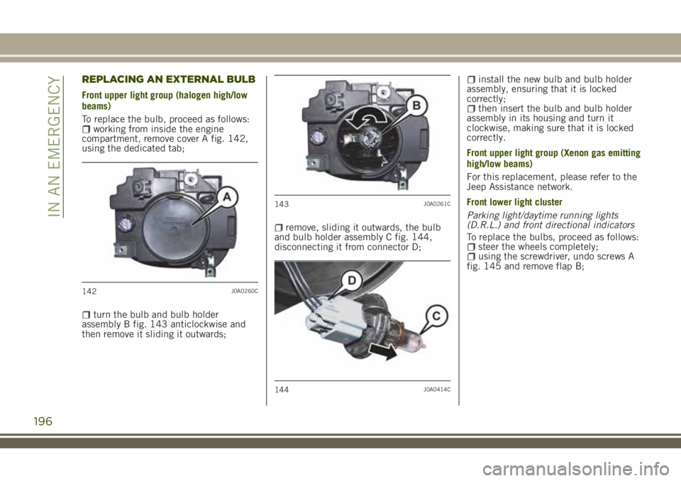
To replace the bulb, proceed as follows:
working from inside the engine
compartment, remove cover A fig. 142,
using the dedicated tab;
turn the bulb and bulb holder
assembly B fig. 143 anticlockwise and
then remove it sliding it outwards;
remove, sliding it outwards, the bulb
and bulb holder assembly C fig. 144,
disconnecting it from connector D;
install the new bulb and bulb holder
assembly, ensuring that it is locked
correctly;
then insert the bulb and bulb holder
assembly in its housing and turn it
clockwise, making sure that it is locked
correctly.
Front upper light group (Xenon gas emitting
high/low beams)
For this replacement, please refer to the
Jeep Assistance network.
Front lower light cluster
Parking light/daytime running lights
(D.R.L.) and front directional indicators
To replace the bulbs, proceed as follows:
steer the wheels completely;using the screwdriver, undo screws A
fig. 145 and remove flap B;
142J0A0260C
143J0A0261C
144J0A0414C
196
IN AN EMERGENCY
Page 203 of 356
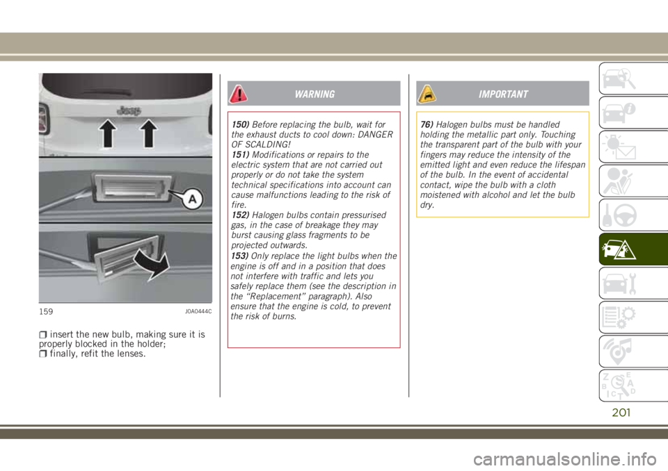
insert the new bulb, making sure it is
properly blocked in the holder;
finally, refit the lenses.
WARNING
150)Before replacing the bulb, wait for
the exhaust ducts to cool down: DANGER
OF SCALDING!
151)Modifications or repairs to the
electric system that are not carried out
properly or do not take the system
technical specifications into account can
cause malfunctions leading to the risk of
fire.
152)Halogen bulbs contain pressurised
gas, in the case of breakage they may
burst causing glass fragments to be
projected outwards.
IMPORTANT
76)Halogen bulbs must be handled
holding the metallic part only. Touching
the transparent part of the bulb with your
fingers may reduce the intensity of the
emitted light and even reduce the lifespan
of the bulb. In the event of accidental
contact, wipe the bulb with a cloth
moistened with alcohol and let the bulb
dry.
159J0A0444C
201
153)Only replace the light bulbs when the
engine is off and in a position that does
not interfere with traffic and lets you
safely replace them (see the description in
the “Replacement” paragraph). Also
ensure that the engine is cold, to prevent
the risk of burns.
Page 204 of 356
REPLACING FUSES
INTRODUCTION
154) 155) 156) 157) 158)
77) 78)
Fuse extracting pliers
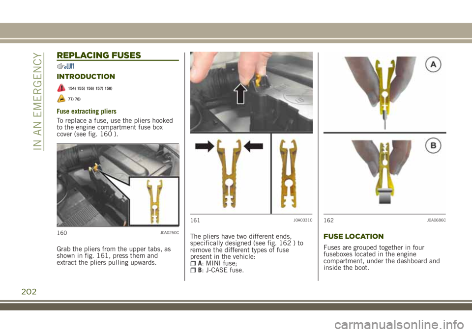
To replace a fuse, use the pliers hooked
to the engine compartment fuse box
cover (see fig. 160 ).
Grab the pliers from the upper tabs, as
shown in fig. 161, press them and
extract the pliers pulling upwards.The pliers have two different ends,
specifically designed (see fig. 162 ) to
remove the different types of fuse
present in the vehicle:
A: MINI fuse;B: J-CASE fuse.
FUSE LOCATION
Fuses are grouped together in four
fuseboxes located in the engine
compartment, under the dashboard and
inside the boot.
160J0A0250C
161J0A0331C162J0A0686C
202
IN AN EMERGENCY
Page 205 of 356
LPG versions
The LPG system components are
protected by specific fuses. Contact a
Jeep Dealership for replacement.
ENGINE COMPARTMENT FUSE
BOX
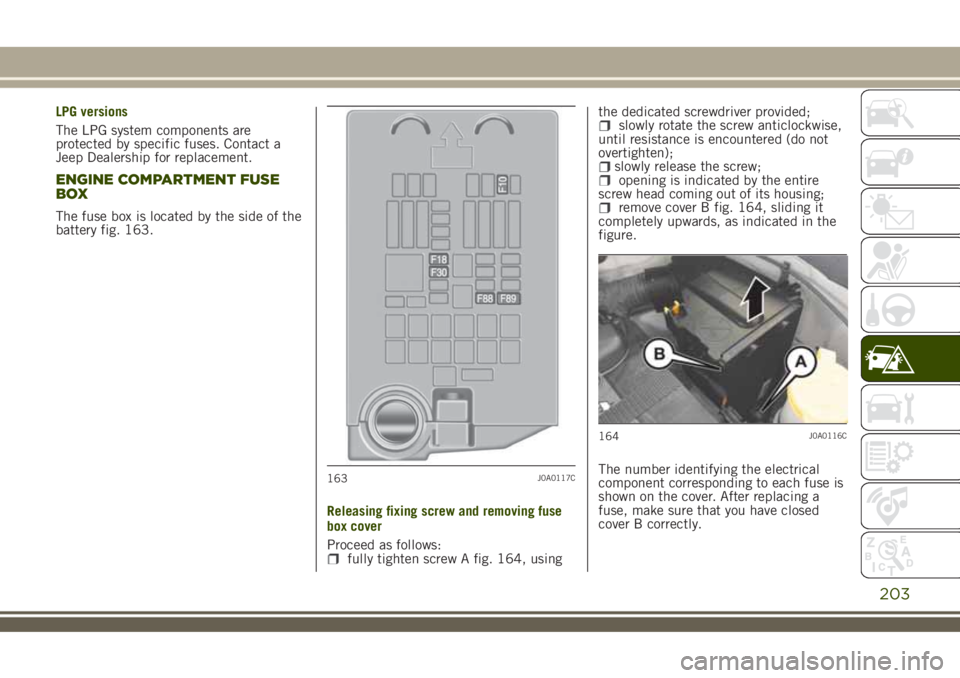
The fuse box is located by the side of the
battery fig. 163.
Releasing fixing screw and removing fuse
box cover
Proceed as follows:
fully tighten screw A fig. 164, usingthe dedicated screwdriver provided;
slowly rotate the screw anticlockwise,
until resistance is encountered (do not
overtighten);
slowly release the screw;opening is indicated by the entire
screw head coming out of its housing;
remove cover B fig. 164, sliding it
completely upwards, as indicated in the
figure.
The number identifying the electrical
component corresponding to each fuse is
shown on the cover. After replacing a
fuse, make sure that you have closed
cover B correctly.
163J0A0117C
164J0A0116C
203
Page 208 of 356
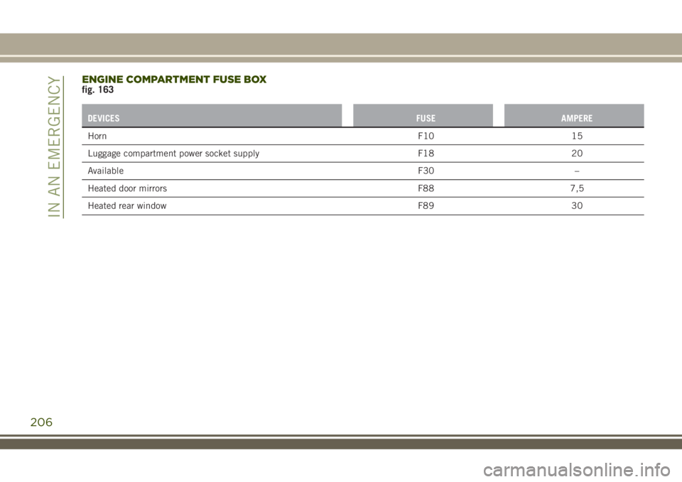
ENGINE COMPARTMENT FUSE BOXfig. 163
DEVICESFUSE AMPERE
HornF10 15
Luggage compartment power socket supply F18 20
AvailableF30 –
Heated door mirrors F88 7,5
Heated rear window F89 30
206
IN AN EMERGENCY