Lancia Ypsilon 2011 Owner handbook (in English)
Manufacturer: LANCIA, Model Year: 2011, Model line: Ypsilon, Model: Lancia Ypsilon 2011Pages: 299, PDF Size: 13.35 MB
Page 61 of 299

CONTROLSHAZARD WARNING LIGHTS
Press the buttonfig. 43 to switch the lights on/off.
Warning lights
and
on the instrument panel
switch on and switch A flashes when the lights are
on.
IMPORTANT The use of hazard warning lights is
governed by the highway code of the country
you are driving in: comply with legal
requirements.
Emergency braking
In the event of emergency braking the hazard
warning lights switch on automatically as well as
warning lights
and
in the instrument panel.
The lights switch off automatically when
emergency braking ceases.FOG LIGHTS
(for versions/markets, where provided)
Press button
fig. 44 to switch the lights on/off.
Press the button again to switch the lights off.
With lights on, warning light
on the instrument
panel will switch on.
REAR FOG LIGHTS
Press button
fig. 44 to switch the lights on/off.
The rear fog lights are only switched on with
the dipped headlights or front fog lights on. Press
the button again to switch the lights off, or switch
off the dipped headlights or the front fog lights
(for versions/markets, where provided).
With the lights on, warning light
in the
instrument panel switches on.
fig. 43
L0F0191
fig. 44
L0F0192
59GETTING TO
KNOW YOUR CARSAFETY
STARTING
AND
DRIVING
WARNING LIGHTS
AND MESSAGES
IN AN EMERGENCY
SERVICING AND
MAINTENANCE
TECHNICAL
SPECIFICATIONS
INDEX
Page 62 of 299

CENTRAL LOCKING
Press button
fig. 45 to lock all the doors
simultaneously (the LED on the button will light
up when the doors are locked). Locking takes
place irrespective of the position of the ignition
key.
DUALDRIVE ELECTRIC POWER STEERING
(for versions/markets, where provided)
Press the CITY button fig. 46 to activate the
function (see paragraph "Dualdrive electric power
steering" in this chapter). When this function is
active, the word CITY on the instrument panel
will light up. To deactivate the function press the
button again.ECO FUNCTION
(for versions/markets, where provided)
Press the ECO button fig. 47 for at least 5 seconds
to activate the function.
When the ECO function is activated, the car is set
for city driving, characterised by less effort on
the steering wheel (Dualdrive system on) and
reduced fuel consumption. When this function is
activated, the word ECO on the display will light
up on some versions.
This function stays in the memory and, when the
vehicle is started again, the system keeps the
setting it had before the engine was stopped. Press
the ECO button again to deactivate the function
and restore the normal driving setting.
fig. 45
L0F0081
fig. 46
L0F0043
60GETTING TO
KNOW YOUR CAR
SAFETY
STARTING
AND
DRIVING
WARNING LIGHTS
AND MESSAGES
IN AN EMERGENCY
SERVICING AND
MAINTENANCE
TECHNICAL
SPECIFICATIONS
INDEX
Page 63 of 299

FUEL CUT-OFF SYSTEM
This intervenes in the case of an impact causing:
❒the interruption of the fuel supply with the
engine consequently cutting out
❒the automatic unlocking of the doors
❒the automatic switching on of the interior lights
❒the switching on of the hazard warning lights.
On some versions, the intervention of the system is
indicated by a message shown on the display.
IMPORTANT Carefully check the car for fuel
leaks, for instance in the engine compartment,
under the car or near the tank area. After a
collision, turn the ignition key to STOP to prevent
the battery from running down.
To restore the correct operation of the car, proceed
as follows:❒turn the ignition key to the MAR position;
❒activate the right direction indicator;
❒deactivate the right direction indicator;
❒activate the left direction indicator;
❒deactivate the left direction indicator;
❒activate the right direction indicator;
❒deactivate the right direction indicator;
❒activate the left direction indicator;
❒deactivate the left direction indicator;
❒turn the ignition key to the STOP position.
WARNING
If, after an impact, you smell fuel or
notice leaks from
the fuel system,
do not reactivate the system to avoid the risk
of fire.
fig. 47
L0F0039
61GETTING TO
KNOW YOUR CARSAFETY
STARTING
AND
DRIVING
WARNING LIGHTS
AND MESSAGES
IN AN EMERGENCY
SERVICING AND
MAINTENANCE
TECHNICAL
SPECIFICATIONS
INDEX
Page 64 of 299

INTERIOR FITTINGSPASSENGER SIDE GLOVE COMPARTMENT
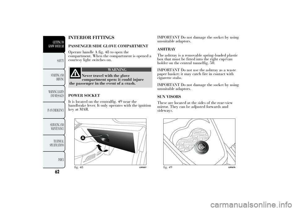
Operate handle A fig. 48 to open the
compartment. When the compartment is opened a
courtesy light switches on.
WARNING
Never travel with the glove
compartment open: it
could injure
the passenger in the event of a crash.
POWER SOCKET
It is located on the centralfig. 49 near the
handbrake lever. It only operates with the ignition
key at MAR.IMPORTANT Do not damage the socket by using
unsuitable adaptors.
ASHTRAY
The ashtray is a removable spring-loaded plastic
box that must be fitted into the right cup/can
holder on the central tunnelfig. 50.
IMPORTANT Do not use the ashtray as a waste
paper basket: it may catch fire in contact with
cigarette stubs.
IMPORTANT Do not damage the socket by using
unsuitable adaptors.
SUN VISORS
These are located at the sides of the rear-view
mirror. They can be adjusted forwards and
sideways.
fig. 48
L0F0057
fig. 49
L0F0076
62GETTING TO
KNOW YOUR CAR
SAFETY
STARTING
AND
DRIVING
WARNING LIGHTS
AND MESSAGES
IN AN EMERGENCY
SERVICING AND
MAINTENANCE
TECHNICAL
SPECIFICATIONS
INDEX
Page 65 of 299

The back of the driver's and passenger side visors
houses two courtesy mirrors. To use the driver's
side mirror, open the sliding cover A fig. 51.EXTINGUISHER
(for versions/markets, where provided)
It is located under the passenger side front seat or,
in some versions, at the right side of the luggage
compartment, inside a dedicated container.
fig. 50
L0F0056
fig. 51
L0F0055
63GETTING TO
KNOW YOUR CARSAFETY
STARTING
AND
DRIVING
WARNING LIGHTS
AND MESSAGES
IN AN EMERGENCY
SERVICING AND
MAINTENANCE
TECHNICAL
SPECIFICATIONS
INDEX
Page 66 of 299

SUN ROOF(for versions/markets, where provided)
The large electric sun roof comprises two glass
panels; the front one is mobile and the rear one
fixed. These are equipped with two sun blinds
(front and rear) that can be moved manually.
With the sun roof closed, the blinds can be placed
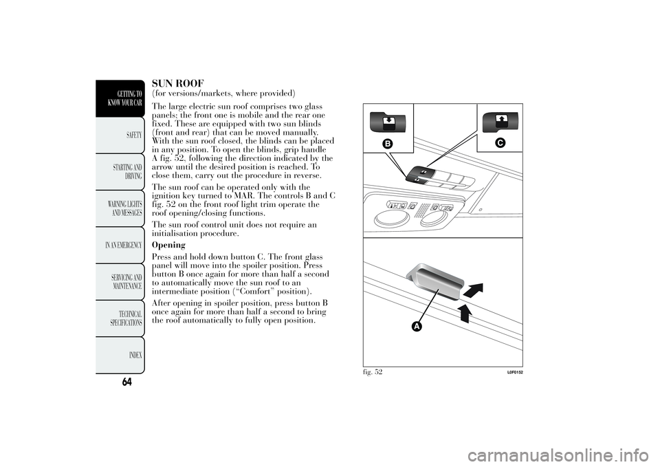
in any position. To open the blinds, grip handle
A fig. 52, following the direction indicated by the
arrow until the desired position is reached. To
close them, carry out the procedure in reverse.
The sun roof can be operated only with the
ignition key turned to MAR. The controls B and C
fig. 52 on the front roof light trim operate the
roof opening/closing functions.
The sun roof control unit does not require an
initialisation procedure.
Opening
Press and hold down button C. The front glass
panel will move into the spoiler position. Press
button B once again for more than half a second
to automatically move the sun roof to an
intermediate position (“Comfort” position).
After opening in spoiler position, press button B
once again for more than half a second to bring
the roof automatically to fully open position.
fig. 52
L0F0152
64GETTING TO
KNOW YOUR CAR
SAFETY
STARTING
AND
DRIVING
WARNING LIGHTS
AND MESSAGES
IN AN EMERGENCY
SERVICING AND
MAINTENANCE
TECHNICAL
SPECIFICATIONS
INDEX
Page 67 of 299

Closing
Press button B from the fully open position. Press
the button again for more than half a second to
automatically move the sun roof to spoiler
position.
Use the sunroof only at “spoiler”
position if a transverse roof rack is
fitted. Do not open the sunroof if there
is snow or ice on it: you may damage it.
WARNING
When leaving the vehicle, always
remove the key
from the ignition to
avoid the risk of injury to those still inside
the car due to accidental operation of the
sunroof. Improper use of the roof can be
dangerous. Before and during operation,
always check that no-one is exposed to the
risk of being injured by the moving sunroof
or by objects getting caught or hit by it.
ANTI-PINCH SAFETY DEVICE
For versions/markets where provided, the sun roof
has an anti-pinch safety system capable of
detecting the presence of an obstacle whilst the
roof is closing; when this happens, the system
stops and the movement of the glass is
immediately reversed.
DOORSDOOR CENTRAL LOCKING/UNLOCKING
Locking the doors from outside
With the doors closed press button
on the
remote control or turn the metal insert (located
inside the key) in the driver's side door lock. The
LED above the
button switches on to indicate
that the doors have been locked.
The door locking function is operated:
❒with all the doors closed;
❒with all the doors closed and the luggage
compartment open.
Unlocking the doors from outside
Press button
on the remote control or turn the
metal insert (located inside the key) in the driver's
side door lock.
Locking/unlocking the doors from inside
Press button. The button has an LED that
indicates whether the doors are locked or
unlocked.
LED on: doors locked. Press button
once again
to centrally unlock all doors. The LED will switch
off.
LED off: doors unlocked. Press the button
again to centrally lock all doors. The doors will
be locked only if all the doors are properly shut.
65GETTING TO
KNOW YOUR CARSAFETY
STARTING
AND
DRIVING
WARNING LIGHTS
AND MESSAGES
IN AN EMERGENCY
SERVICING AND
MAINTENANCE
TECHNICAL
SPECIFICATIONS
INDEX
Page 68 of 299

Once the doors have been locked via the remote
control or the key pawl, it will no longer be
possible to unlock them by pressing button
.
In the absence of electrical power supply (blown
fuse, battery disconnected, etc.) it is still possible
to lock the doors manually.
IMPORTANT With central locking active, pulling
the internal opening lever of the passenger side
door unlocks the door (the LED stays on). Pulling
the internal opening lever of the driver side door
activates central unlocking.
IMPORTANT The rear doors cannot be opened
from the inside when the child-lock system is
engaged (see the description in the following
paragraph).
CHILD-LOCKS
This system prevents the rear doors from being
opened from the inside.
This device A fig. 53 can only be engaged with the
doors open:
❒position 1 - device engaged (door locked);
❒position 2 - device not engaged (door may be
opened from the inside).
The device remains on even if the doors are
unlocked electrically.
IMPORTANT The rear doors cannot be opened
from the inside when the child-lock system is
engaged.
fig. 53
L0F0080
66GETTING TO
KNOW YOUR CAR
SAFETY
STARTING
AND
DRIVING
WARNING LIGHTS
AND MESSAGES
IN AN EMERGENCY
SERVICING AND
MAINTENANCE
TECHNICAL
SPECIFICATIONS
INDEX
Page 69 of 299

WARNING
Always use this device when carrying
children. After engaging
the child
lock on both rear doors, check for effective
engagement by trying to open a door with
the internal handle.
PASSENGER SIDE FRONT DOOR AND REAR
DOOR EMERGENCY LOCKING DEVICE
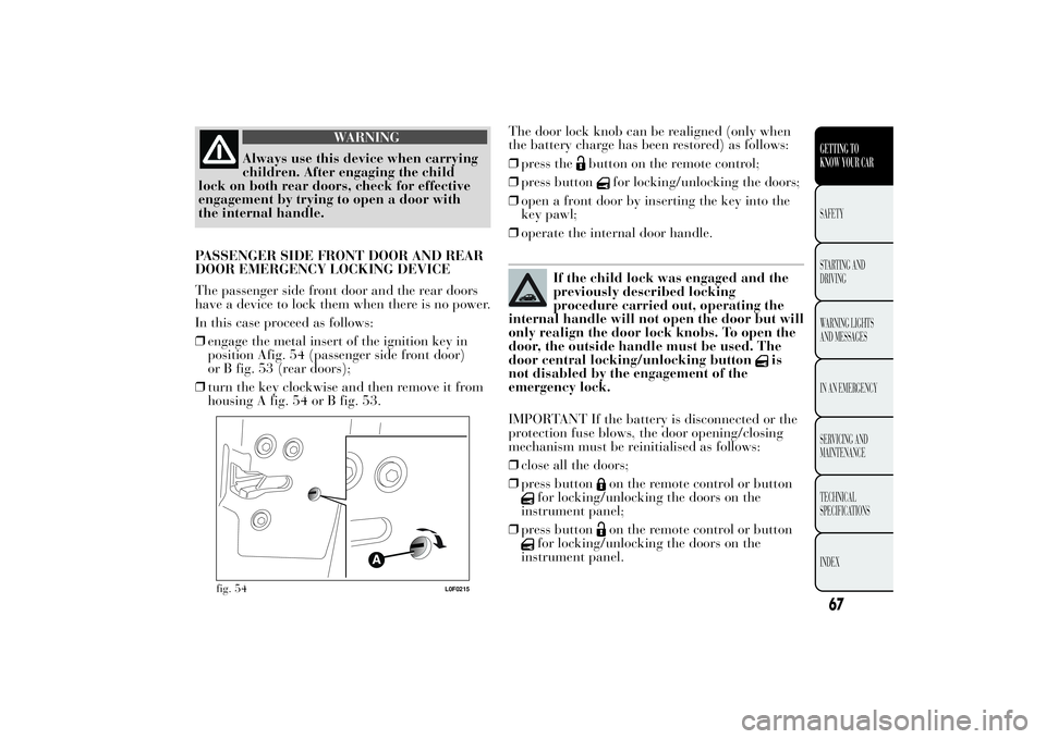
The passenger side front door and the rear doors
have a device to lock them when there is no power.
In this case proceed as follows:
❒engage the metal insert of the ignition key in
position Afig. 54 (passenger side front door)
or B fig. 53 (rear doors);
❒turn the key clockwise and then remove it from
housing A fig. 54 or B fig. 53.The door lock knob can be realigned (only when
the battery charge has been restored) as follows:
❒press the
button on the remote control;
❒press button
for locking/unlocking the doors;
❒open a front door by inserting the key into the
key pawl;
❒operate the internal door handle.
If the child lock was engaged and the
previously described locking
procedure carried out, operating the
internal handle will not open the door but will
only realign the door lock knobs. To open the
door, the outside handle must be used. The
door central locking/unlocking button
is
not disabled by the engagement of the
emergency lock.
IMPORTANT If the battery is disconnected or the
protection fuse blows, the door opening/closing
mechanism must be reinitialised as follows:
❒close all the doors;
❒press button
on the remote control or button
for locking/unlocking the doors on the
instrument panel;
❒press button
on the remote control or button
for locking/unlocking the doors on the
instrument panel.
fig. 54
L0F0215
67GETTING TO
KNOW YOUR CARSAFETY
STARTING
AND
DRIVING
WARNING LIGHTS
AND MESSAGES
IN AN EMERGENCY
SERVICING AND
MAINTENANCE
TECHNICAL
SPECIFICATIONS
INDEX
Page 70 of 299

ELECTRIC WINDOWSThese operate when the ignition key is turned to
MAR and for about three minutes after turning
the key to STOP or removing it if one of the front
doors is open.
The control buttons are located in the door panels
(for versions/markets, where provided) (the driver
side door panel can be used to operate all the
windows).
An anti-crush device operates when the front and
rear windows are raised (for versions/markets,
where provided).
WARNING
Improper use of the electric windows
can be dangerous.
Before and during
operation, always check that passengers are
not exposed to the risk of being injured
either directly by the moving windows or
through objects getting caught or struck by
them. When leaving the car, always remove
the ignition key to avoid the risk of injury
of people still on board due to accidental
operation of the electric windows.CONTROLS
Driver side front doorfig. 55
A: opening/closing front left window; "continuous
automatic" operation during window opening/
closing stage
B: opening/closing front right window;
"continuous automatic" operation during window
opening/closing stage (for versions/markets,
where provided)
C: enabling/disabling of rear door electric window
controls
D: opening/closing rear left window (for
versions/markets, where provided); "continuous
automatic" operation during window opening/
closing stage
E: opening/closing rear right window (for
versions/markets, where provided); "continuous
automatic" operation during window opening/
closing stage.
Push the buttons to open/close the desired
window. When one of the two buttons is pressed
briefly, the window moves in stages; if the button
is held down, "continuous automatic" operation
is activated both for closing and opening.
If the control button is pressed again, the window
will stop in the desired position. If the button is
held down for several seconds, the window raises
or lowers automatically (only with ignition key
in MAR position).
68GETTING TO
KNOW YOUR CAR
SAFETY
STARTING
AND
DRIVING
WARNING LIGHTS
AND MESSAGES
IN AN EMERGENCY
SERVICING AND
MAINTENANCE
TECHNICAL
SPECIFICATIONS
INDEX