LAND ROVER DISCOVERY 2002 Workshop Manual
Manufacturer: LAND ROVER, Model Year: 2002, Model line: DISCOVERY, Model: LAND ROVER DISCOVERY 2002Pages: 1672, PDF Size: 46.1 MB
Page 441 of 1672

ENGINE MANAGEMENT SYSTEM - TD5
18-1-48 REPAIRS
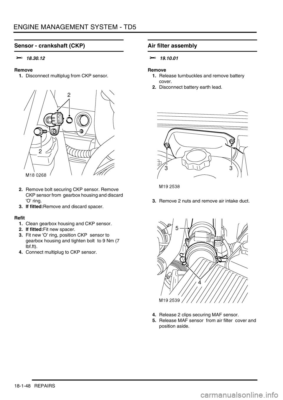
Sensor - crankshaft (CKP)
$% 18.30.12
Remove
1.Disconnect multiplug from CKP sensor.
2.Remove bolt securing CKP sensor. Remove
CKP sensor from gearbox housing and discard
'O' ring.
3. If fitted:Remove and discard spacer.
Refit
1.Clean gearbox housing and CKP sensor.
2. If fitted:Fit new spacer.
3.Fit new 'O' ring, position CKP sensor to
gearbox housing and tighten bolt to 9 Nm (7
lbf.ft).
4.Connect multiplug to CKP sensor.
Air filter assembly
$% 19.10.01
Remove
1.Release turnbuckles and remove battery
cover.
2.Disconnect battery earth lead.
3.Remove 2 nuts and remove air intake duct.
4.Release 2 clips securing MAF sensor.
5.Release MAF sensor from air filter cover and
position aside.
Page 442 of 1672

ENGINE MANAGEMENT SYSTEM - TD5
REPAIRS 18-1-49
6.Release air filter from 3 grommets, remove
assembly and discard 'O' ring.
7.Remove 2 screws, remove AAP sensor and
discard 'O' ring.
Refit
1.Clean MAF sensor and air filter mating faces.
2.Fit new 'O' ring to air filter.
3.Clean AAP sensor.
4.Using new 'O' ring, fit AAP sensor and tighten
screws.
5.Position air filter assembly and secure in
grommets.
6.Position MAF sensor and secure clips.
7.Position intake duct to air filter and tighten nuts.
8.Connect battery earth lead.
9.Fit battery cover and secure with fixings.
Element - air filter
$% 19.10.10
Remove
1.Release 2 clips and disconnect MAF sensor
from air filter cover.
Page 443 of 1672

ENGINE MANAGEMENT SYSTEM - TD5
18-1-50 REPAIRS
2.Disconnect multiplug from AAP sensor.
3.Release 2 clips and remove cover from air
filter.
4.Remove air filter element.
Refit
1.Clean air filter body and cover.
2.Fit new air filter element.
3.Position air cleaner cover and secure clips.
4.Position MAF sensor and secure clips.
5.Connect multiplug to AAP sensor.
Sensor - fuel temperature
$% 19.22.08
Remove
1.Remove 3 bolts and remove engine acoustic
cover.
2.Release fixings and remove battery cover.
3.Disconnect battery earth lead.
4.Disconnect multiplug from fuel temperature
sensor.
5. Thoroughly clean area around fuel
temperature sensor before removal.
6.Remove fuel temperature sensor and discard
sealing washer.
Refit
1.Clean fuel temperature sensor mating faces.
2.Fit new sealing washer and tighten fuel
temperature sensor to 13 Nm (10 lbf.ft) .
3.Connect multiplug to fuel temperature sensor.
4.Connect battery earth lead.
5.Fit battery cover and secure fixings.
6.Fit engine acoustic cover, and secure with
fixings.
Page 444 of 1672

ENGINE MANAGEMENT SYSTEM - TD5
REPAIRS 18-1-51
Sensor - mass air flow (MAF)
$% 19.22.25
Remove
1.Disconnect multiplug from MAF sensor.
2.Loosen clip and release air intake hose from
MAF sensor.
3.Release 2 clips and remove sensor from air
cleaner.
Refit
1.Position sensor to air cleaner and secure clips.
2.Position air intake hose and tighten clip.
3.Connect multiplug to MAF sensor.
Sensor - combined MAP and IAT
$% 19.22.26
Remove
1.Remove 3 bolts and remove engine acoustic
cover.
2.Disconnect multiplug from combined MAP and
IAT sensor,
3.Remove 2 bolts securing sensor to inlet
manifold.
4.Remove sensor and discard 'O' ring.
Refit
1.Clean sensor and inlet manifold mating face.
2.Fit new 'O' ring and position sensor to manifold.
3.Fit bolts securing MAP and IAT sensor and
tighten to 9 Nm (7 lbf.ft).
4.Fit engine acoustic cover and secure with
fixings.
Page 445 of 1672

ENGINE MANAGEMENT SYSTEM - TD5
18-1-52 REPAIRS
Sensor - ambient air pressure (AAP)
$% 19.22.27
Remove
1.Release 2 clips and disconnect MAF sensor
from air cleaner cover. 2.Release 2 clips and release cover from air
cleaner.
3.Disconnect multiplug from AAP sensor, remove
2 screws, remove sensor and discard 'O' ring.
Refit
1.Clean AAP sensor and air cleaner cover.
2.Fit new 'O' ring, fit sensor and tighten screws.
3.Position air cleaner cover and secure clips.
4.Connect multiplug to AAP sensor.
5.Position MAF sensor and secure clips.
Page 446 of 1672

ENGINE MANAGEMENT SYSTEM - TD5
REPAIRS 18-1-53
Element - fuel filter
$% 19.25.07
Remove
1.Release turnbuckles and remove battery cover.
2.Disconnect battery earth lead.
3.Raise rear of vehicle.
WARNING: Do not work on or under a
vehicle supported only by a jack. Always
support the vehicle on safety stands.
4.Clean area around fuel filter.
5.Disconnect multiplug from filter element.
6.Remove fuel filter element.
Refit
1.Clean fuel filter and mating face.
2.Fit new fuel filter element and connect
multiplug.
3.Remove stand(s) and lower vehicle.
4.Connect battery earth lead.
5.Fit battery cover and secure the fixings.
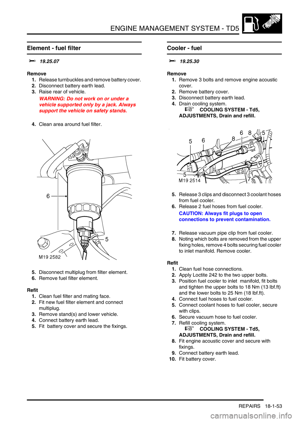
Cooler - fuel
$% 19.25.30
Remove
1.Remove 3 bolts and remove engine acoustic
cover.
2.Remove battery cover.
3.Disconnect battery earth lead.
4.Drain cooling system.
+ COOLING SYSTEM - Td5,
ADJUSTMENTS, Drain and refill.
5.Release 3 clips and disconnect 3 coolant hoses
from fuel cooler.
6.Release 2 fuel hoses from fuel cooler.
CAUTION: Always fit plugs to open
connections to prevent contamination.
7.Release vacuum pipe clip from fuel cooler.
8.Noting which bolts are removed from the upper
fixing holes, remove 4 bolts securing fuel cooler
to inlet manifold. Remove cooler.
Refit
1.Clean fuel hose connections.
2.Apply Loctite 242 to the two upper bolts.
3.Position fuel cooler to inlet manifold, fit bolts
and tighten the upper bolts to 18 Nm (13 lbf.ft)
and the lower bolts to 25 Nm (18 lbf.ft).
4.Connect fuel hoses to fuel cooler.
5.Connect coolant hoses to fuel cooler, secure
with clips.
6.Secure vacuum hose to fuel cooler.
7.Refill cooling system.
+ COOLING SYSTEM - Td5,
ADJUSTMENTS, Drain and refill.
8.Fit engine acoustic cover and secure with
fixings.
9.Connect battery earth lead.
10.Fit battery cover.
Page 447 of 1672

ENGINE MANAGEMENT SYSTEM - TD5
18-1-54 REPAIRS
Sensor - Throttle position (TP)
$% 19.30.14
The TP sensor is integral with the throttle pedal
assembly and must be renewed as an assembly.
Three track TP sensors were introduced from VIN
297137.
Three track TP sensors cannot be fitted to vehicles
previously fitted with two track TP sensors.
Remove
1.Release diagnostic socket from driver's closing
panel.
2.Remove 3 trim retaining studs and remove
closing panel. 3.Disconnect multiplug from TP sensor, release
harness from throttle pedal bracket and
position harness aside..
4.Remove 2 nyloc nuts and remove throttle pedal
assembly. Discard nuts.
5.Remove spacer block from pedal bracket.
Refit
1.Position spacer block to pedal bracket.
2.Position throttle pedal assembly and tighten
new nyloc nuts to 13 Nm (10 lbf.ft).
3.Fit and secure harness to pedal bracket and
connect multiplug to TP sensor.
4.Position closing panel, connect diagnostic
socket and fit retaining studs.
Page 448 of 1672

ENGINE MANAGEMENT SYSTEM - TD5
REPAIRS 18-1-55
Turbocharger
$% 19.42.01
Remove
1.Remove 3 bolts and remove engine acoustic
cover.
2.Release fixings and remove battery cover.
3.Disconnect battery earth lead.
4.Remove cooling fan cover.
5.Remove 3 bolts and remove exhaust manifold
heat shield.
6.Release clip and disconnect breather hose
from camshaft cover.
7.Release clip and disconnect vacuum hose from
turbocharger wastegate.
8.Loosen clips and release air intake and outlet
hoses from turbocharger. 9.Remove turbocharger oil feed banjo bolt and
discard sealing washers.
10.Remove 2 bolts and release turbocharger oil
drain pipe and discard gasket.
11.Remove 3 nuts and release exhaust front pipe
from turbocharger and discard gasket.
12.Remove 3 nuts securing turbocharger to
exhaust manifold.
13. Remove turbocharger and discard gasket.
Refit
1.Clean turbocharger and exhaust manifold
mating faces.
2.Using a new gasket, fit turbocharger to exhaust
manifold and tighten nuts to 30 Nm (22 lbf.ft).
3.Using new gasket, align exhaust front pipe and
tighten nuts to 30 Nm (22 lbf.ft).
4.Using new gasket, align turbocharger drain
pipe and tighten bolts to 9 Nm (7 lbf.ft).
5.Fit banjo bolt to oil feed pipe using new sealing
washers and tighten to 25 Nm (18 lbf.ft)..
6.Position air hoses to turbocharger and tighten
clips.
7.Position and secure breather hose to camshaft
cover.
8.Position and secure vacuum hose to
turbocharger wastegate.
9.Position exhaust manifold heat shield and
tighten M6 bolts to 9 Nm (7 lbf.ft) and M8 bolt to
25 Nm (18 lbf.ft).
10.Fit fan cowl and secure fixings.
11.Fit acoustic cover and secure the fixings.
12.Connect battery earth lead.
13.Fit battery cover and secure fixings.
Page 449 of 1672

ENGINE MANAGEMENT SYSTEM - TD5
18-1-56 REPAIRS
Intercooler
$% 19.42.15
Remove
1.Remove cooling fan and coupling.
+ COOLING SYSTEM - Td5, REPAIRS,
Fan - viscous.
2.Remove battery.
3.Remove vehicle jack from battery carrier.
4.Remove screw and release engine control
module (ECM) from battery carrier.
5.Remove 7 bolts and remove battery carrier. 6.Remove 2 screws and remove lower half of fan
cowl.
7.Remove front grille.
+ EXTERIOR FITTINGS, REPAIRS,
Grille - front - up to 03MY.
8.Remove 6 scrivets and remove LH and RH air
deflectors from front panel.
Page 450 of 1672

ENGINE MANAGEMENT SYSTEM - TD5
REPAIRS 18-1-57
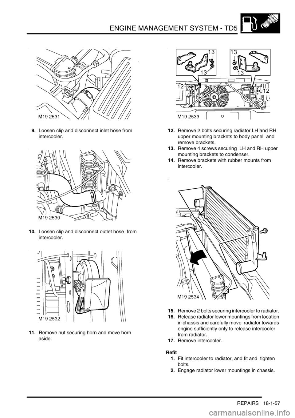
9.Loosen clip and disconnect inlet hose from
intercooler.
10.Loosen clip and disconnect outlet hose from
intercooler.
11.Remove nut securing horn and move horn
aside. 12.Remove 2 bolts securing radiator LH and RH
upper mounting brackets to body panel and
remove brackets.
13.Remove 4 screws securing LH and RH upper
mounting brackets to condenser.
14.Remove brackets with rubber mounts from
intercooler.
15.Remove 2 bolts securing intercooler to radiator.
16.Release radiator lower mountings from location
in chassis and carefully move radiator towards
engine sufficiently only to release intercooler
from radiator.
17.Remove intercooler.
Refit
1.Fit intercooler to radiator, and fit and tighten
bolts.
2.Engage radiator lower mountings in chassis.