LAND ROVER FREELANDER 2001 Workshop Manual
Manufacturer: LAND ROVER, Model Year: 2001, Model line: FREELANDER, Model: LAND ROVER FREELANDER 2001Pages: 1007, PDF Size: 23.47 MB
Page 221 of 1007

ENGINE - K SERIES KV6
12-3-44 REPAIRS
35.Fit rear beam.
+ FRONT SUSPENSION, REPAIRS,
Rear beam.
36.Fill IRD to correct level with fluid.
+ INTERMEDIATE REDUCTION
DRIVE, ADJUSTMENTS, Intermediate
reduction drive (IRD) lubrication system -
drain & refill - NAS.
37.Fit exhaust front pipe.
+ MANIFOLDS & EXHAUST SYSTEMS
- K SERIES KV6, REPAIRS, Front pipe - NAS.
38.With assistant depressing the brake pedal,
tighten front hub nuts to 400 Nm.
39.Stake nuts to drive shafts
40.Fit front road wheels, fit and tighten nuts to 115
Nm.
41.Lower vehicle on lift.
42.Connect brake servo vacuum hose to inlet
manifold chamber.
43.Connect coolant hose to underside of
expansion tank and secure with clip.
44.Connect expansion tank hose to inlet manifold
and secure clip.
45.Connect top hose to radiator and secure with
clip. Position hose in bracket.
46.Connect heater feed and return hoses and
secure with clips.
47.Connect throttle inner cable to throttle cam and
secure outer cable in abutment bracket.
48.Connect hose to purge valve.
49.Fit purge hose into clip.
50.Connect fuel hose to fuel rail pipe, fit rubber
sleeve over hose connector.
51.Connect gearbox harness multiplugs and
secure multiplugs in mounting bracket clips.
52.Connect Lucar connector to starter solenoid.
53.Position earth lead to gearbox housing, fit and
tighten bolt to 25 Nm.
54.Position engine harness to 'E' box mounting
bracket and secure with clips.
55.Connect earth header multiplug.
56.Connect multiplug to under bonnet fuse box.
57.Position battery and starter motor lead to under
bonnet fuse box, fit and tighten bolts to 8 Nm.
58.Fit under bonnet fuse box cover.
59.Position 'E' box, secure in retaining clip, fit and
tighten nut to 9 Nm.
60.Fit carrier to 'E' box.
61.Fit air ducting to 'E' box.
62.Fit body harness to 'E' box, secure grommet
and harness clip.
63.Connect 'E' box cooling fan multiplug.
64.Connect multiplug to 'E' box temperature
sensor.
65.Connect multiplug to gearbox ECU.
66.Position engine harness to 'E' box and secure
grommet.67.Fit engine harness clamp and secure with
screws.
68.Connect engine harness multiplug to body
harness multiplug and fit multiplug to 'E' box.
69.Fit heated front screen harness to battery
positive cable and tighten bolt to 15 Nm (11
lbf.ft).
70.Fit engine ECM.
+ ENGINE MANAGEMENT SYSTEM -
SIEMENS, REPAIRS, Engine control module
(ECM) - fuel - NAS.
71.Fit battery carrier.
+ CHARGING AND STARTING,
REPAIRS, Carrier - battery.
72.Fill cooling system.
+ COOLING SYSTEM - K SERIES KV6,
ADJUSTMENTS, Coolant - drain and refill.
73.Connect the battery earth lead.
74.Fill gearbox with fluid.
+ AUTOMATIC GEARBOX - JATCO,
ADJUSTMENTS, Gearbox fluid - drain &
refill.
75.Fit the engine acoustic cover.
+ ENGINE - K SERIES KV6, REPAIRS,
Cover - engine acoustic.
76.Untie and close bonnet.
Page 222 of 1007
ENGINE - K SERIES KV6
REPAIRS 12-3-45
Arm assembly - engine mounting RH
$% 12.45.06
Remove
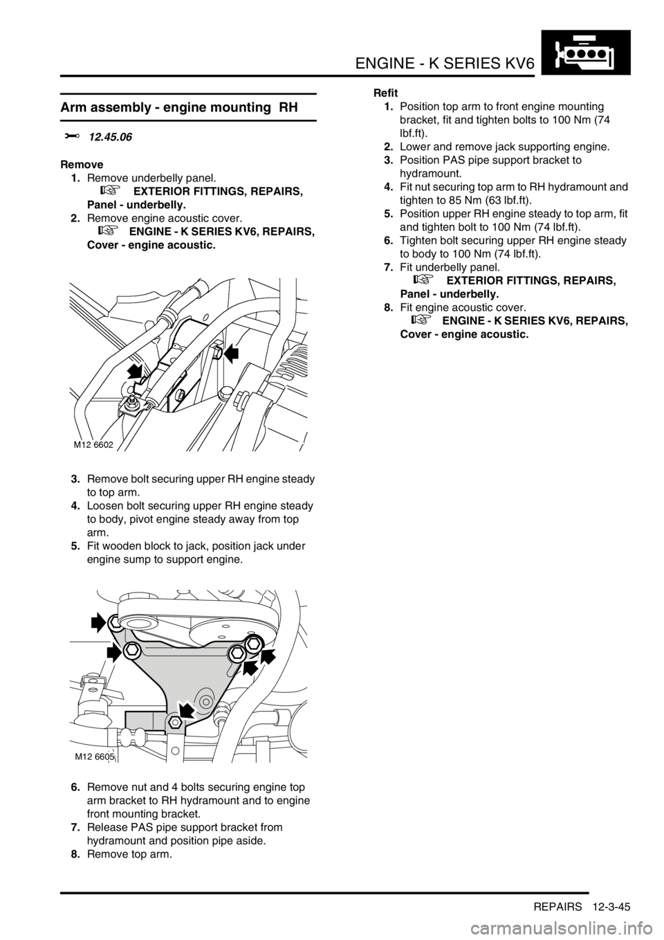
1.Remove underbelly panel.
+ EXTERIOR FITTINGS, REPAIRS,
Panel - underbelly.
2.Remove engine acoustic cover.
+ ENGINE - K SERIES KV6, REPAIRS,
Cover - engine acoustic.
3.Remove bolt securing upper RH engine steady
to top arm.
4.Loosen bolt securing upper RH engine steady
to body, pivot engine steady away from top
arm.
5.Fit wooden block to jack, position jack under
engine sump to support engine.
6.Remove nut and 4 bolts securing engine top
arm bracket to RH hydramount and to engine
front mounting bracket.
7.Release PAS pipe support bracket from
hydramount and position pipe aside.
8.Remove top arm.Refit
1.Position top arm to front engine mounting
bracket, fit and tighten bolts to 100 Nm (74
lbf.ft).
2.Lower and remove jack supporting engine.
3.Position PAS pipe support bracket to
hydramount.
4.Fit nut securing top arm to RH hydramount and
tighten to 85 Nm (63 lbf.ft).
5.Position upper RH engine steady to top arm, fit
and tighten bolt to 100 Nm (74 lbf.ft).
6.Tighten bolt securing upper RH engine steady
to body to 100 Nm (74 lbf.ft).
7.Fit underbelly panel.
+ EXTERIOR FITTINGS, REPAIRS,
Panel - underbelly.
8.Fit engine acoustic cover.
+ ENGINE - K SERIES KV6, REPAIRS,
Cover - engine acoustic.
M12 6605
Page 223 of 1007
ENGINE - K SERIES KV6
12-3-46 REPAIRS
Engine mounting - LH
$% 12.45.11
Remove
1.Remove engine acoustic cover.
+ ENGINE - K SERIES KV6, REPAIRS,
Cover - engine acoustic.
2.Remove battery carrier.
+ CHARGING AND STARTING,
REPAIRS, Carrier - battery.
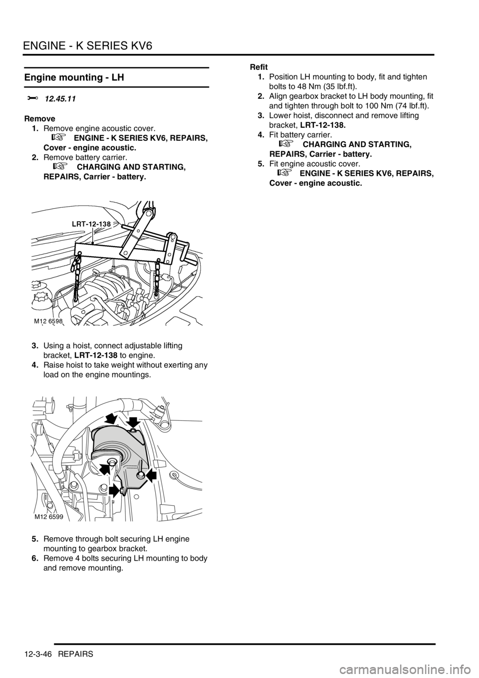
3.Using a hoist, connect adjustable lifting
bracket, LRT-12-138 to engine.
4.Raise hoist to take weight without exerting any
load on the engine mountings.
5.Remove through bolt securing LH engine
mounting to gearbox bracket.
6.Remove 4 bolts securing LH mounting to body
and remove mounting.Refit
1.Position LH mounting to body, fit and tighten
bolts to 48 Nm (35 lbf.ft).
2.Align gearbox bracket to LH body mounting, fit
and tighten through bolt to 100 Nm (74 lbf.ft).
3.Lower hoist, disconnect and remove lifting
bracket, LRT-12-138.
4.Fit battery carrier.
+ CHARGING AND STARTING,
REPAIRS, Carrier - battery.
5.Fit engine acoustic cover.
+ ENGINE - K SERIES KV6, REPAIRS,
Cover - engine acoustic.
M12 6599
Page 224 of 1007
ENGINE - K SERIES KV6
REPAIRS 12-3-47
Hydramount - engine - RH
$% 12.45.12
Remove
1.Remove top arm.
+ ENGINE - K SERIES KV6, REPAIRS,
Arm assembly - engine mounting RH.
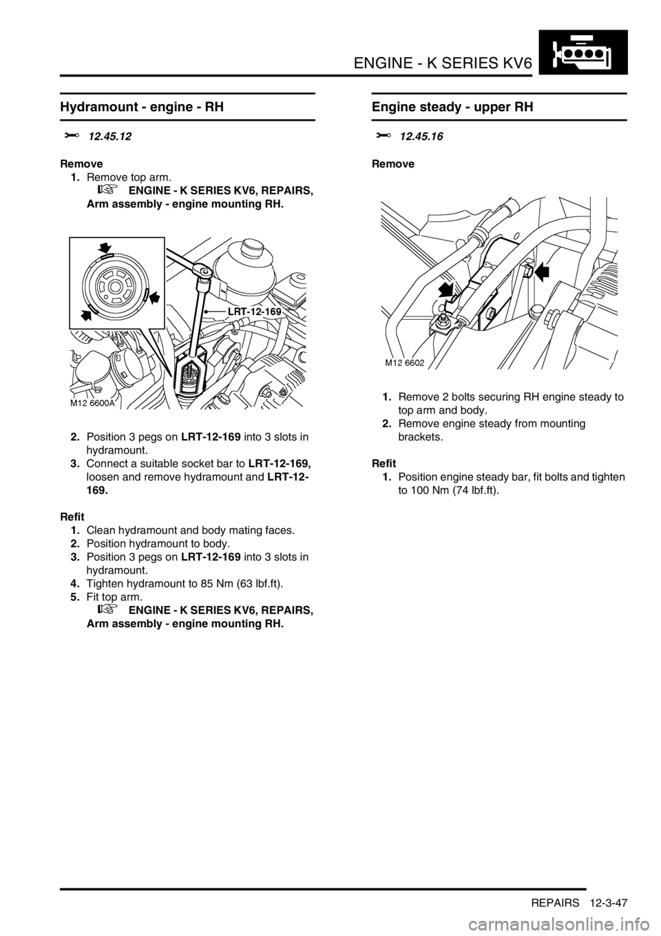
2.Position 3 pegs on LRT-12-169 into 3 slots in
hydramount.
3.Connect a suitable socket bar to LRT-12-169,
loosen and remove hydramount and LRT-12-
169.
Refit
1.Clean hydramount and body mating faces.
2.Position hydramount to body.
3.Position 3 pegs on LRT-12-169 into 3 slots in
hydramount.
4.Tighten hydramount to 85 Nm (63 lbf.ft).
5.Fit top arm.
+ ENGINE - K SERIES KV6, REPAIRS,
Arm assembly - engine mounting RH.
Engine steady - upper RH
$% 12.45.16
Remove
1.Remove 2 bolts securing RH engine steady to
top arm and body.
2.Remove engine steady from mounting
brackets.
Refit
1.Position engine steady bar, fit bolts and tighten
to 100 Nm (74 lbf.ft).
Page 225 of 1007
ENGINE - K SERIES KV6
12-3-48 REPAIRS
Engine steady - lower
$% 12.45.17
Remove
1.Remove underbelly panel.
+ EXTERIOR FITTINGS, REPAIRS,
Panel - underbelly.
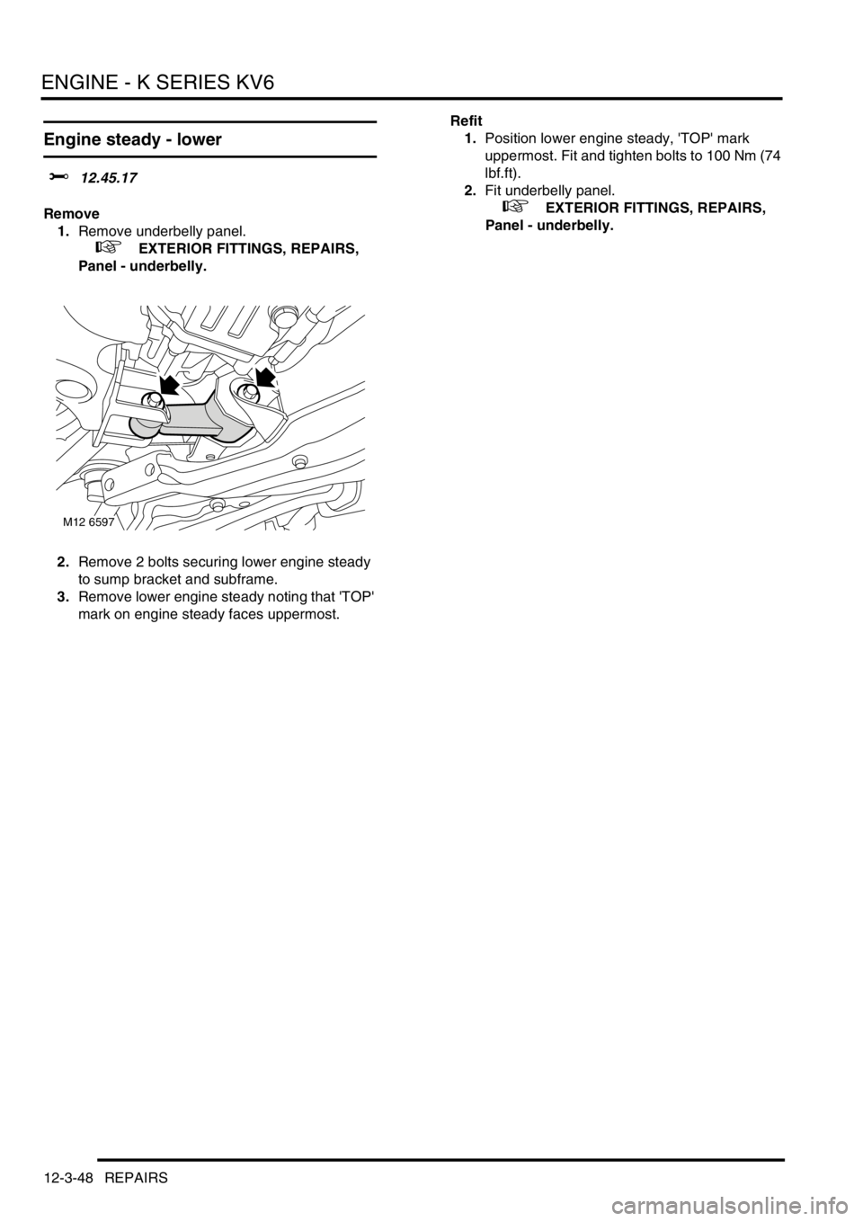
2.Remove 2 bolts securing lower engine steady
to sump bracket and subframe.
3.Remove lower engine steady noting that 'TOP'
mark on engine steady faces uppermost.Refit
1.Position lower engine steady, 'TOP' mark
uppermost. Fit and tighten bolts to 100 Nm (74
lbf.ft).
2.Fit underbelly panel.
+ EXTERIOR FITTINGS, REPAIRS,
Panel - underbelly.
M12 6597
Page 226 of 1007
ENGINE - K SERIES KV6
REPAIRS 12-3-49
Torque converter drive plate
$% 12.53.13
Remove
1.Remove automatic gearbox.
+ AUTOMATIC GEARBOX - JATCO,
REPAIRS, Gearbox - KV6.
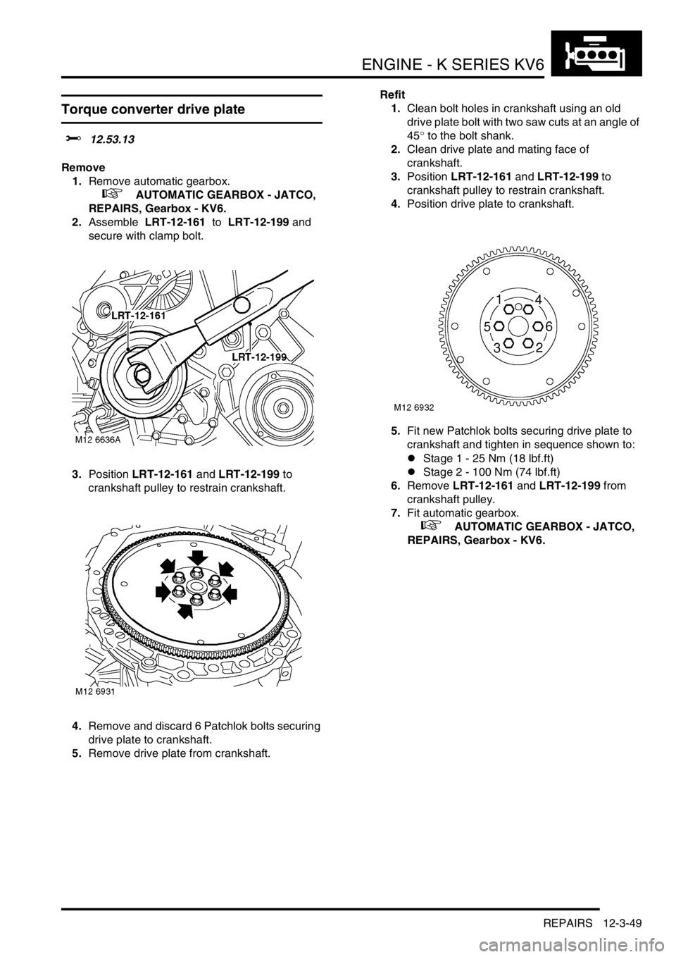
2.Assemble LRT-12-161 to LRT-12-199 and
secure with clamp bolt.
3.Position LRT-12-161 and LRT-12-199 to
crankshaft pulley to restrain crankshaft.
4.Remove and discard 6 Patchlok bolts securing
drive plate to crankshaft.
5.Remove drive plate from crankshaft.Refit
1.Clean bolt holes in crankshaft using an old
drive plate bolt with two saw cuts at an angle of
45° to the bolt shank.
2.Clean drive plate and mating face of
crankshaft.
3.Position LRT-12-161 and LRT-12-199 to
crankshaft pulley to restrain crankshaft.
4.Position drive plate to crankshaft.
5.Fit new Patchlok bolts securing drive plate to
crankshaft and tighten in sequence shown to:
lStage 1 - 25 Nm (18 lbf.ft)
lStage 2 - 100 Nm (74 lbf.ft)
6.Remove LRT-12-161 and LRT-12-199 from
crankshaft pulley.
7.Fit automatic gearbox.
+ AUTOMATIC GEARBOX - JATCO,
REPAIRS, Gearbox - KV6.
Page 227 of 1007
ENGINE - K SERIES KV6
12-3-50 REPAIRS
Filter - engine oil
$% 12.60.04
Remove
1.Raise vehicle on a 4 post ramp.
2.Remove underbelly panel.
+ EXTERIOR FITTINGS, REPAIRS,
Panel - underbelly.
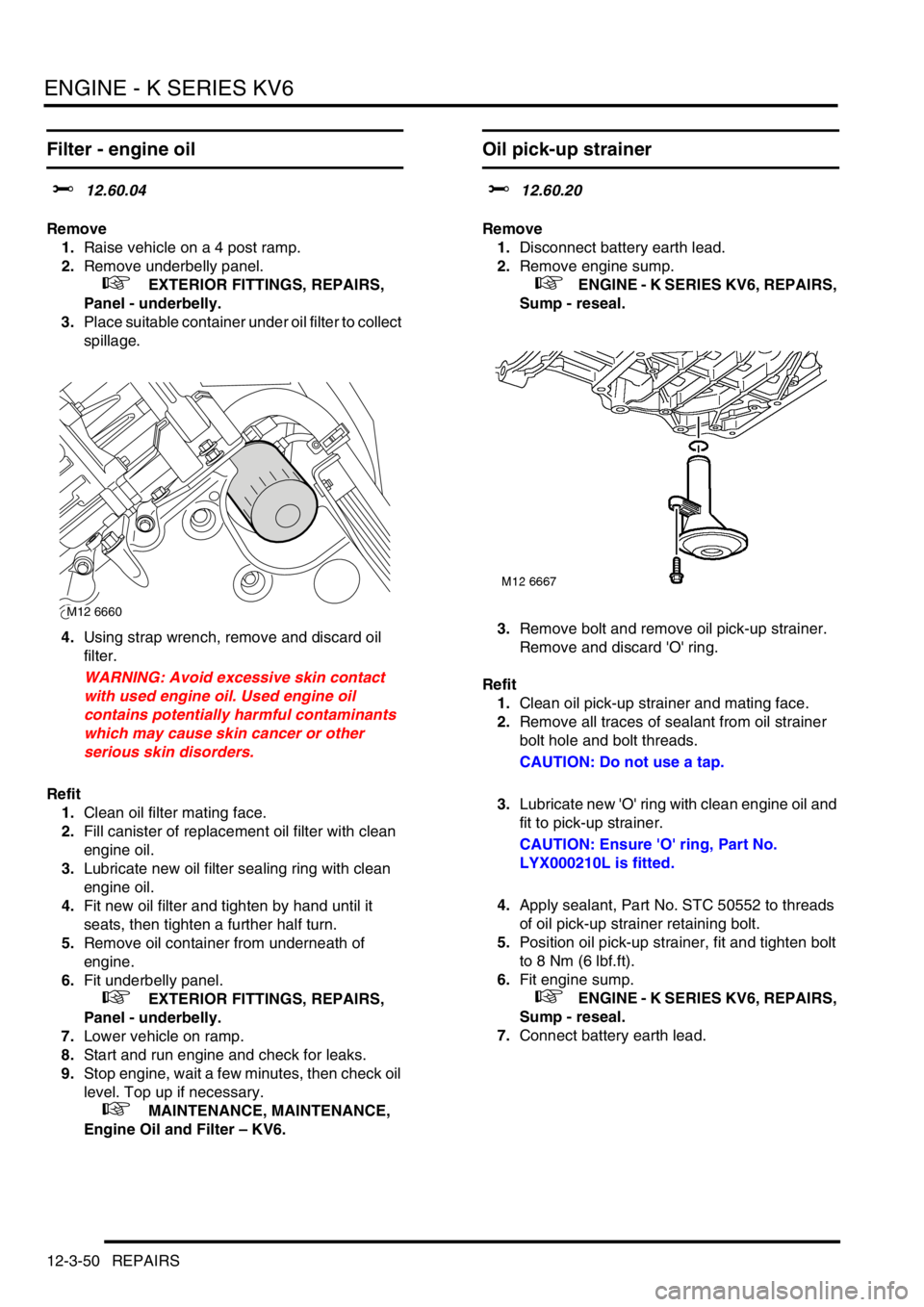
3.Place suitable container under oil filter to collect
spillage.
4.Using strap wrench, remove and discard oil
filter.
WARNING: Avoid excessive skin contact
with used engine oil. Used engine oil
contains potentially harmful contaminants
which may cause skin cancer or other
serious skin disorders.
Refit
1.Clean oil filter mating face.
2.Fill canister of replacement oil filter with clean
engine oil.
3.Lubricate new oil filter sealing ring with clean
engine oil.
4.Fit new oil filter and tighten by hand until it
seats, then tighten a further half turn.
5.Remove oil container from underneath of
engine.
6.Fit underbelly panel.
+ EXTERIOR FITTINGS, REPAIRS,
Panel - underbelly.
7.Lower vehicle on ramp.
8.Start and run engine and check for leaks.
9.Stop engine, wait a few minutes, then check oil
level. Top up if necessary.
+ MAINTENANCE, MAINTENANCE,
Engine Oil and Filter – KV6.
Oil pick-up strainer
$% 12.60.20
Remove
1.Disconnect battery earth lead.
2.Remove engine sump.
+ ENGINE - K SERIES KV6, REPAIRS,
Sump - reseal.
3.Remove bolt and remove oil pick-up strainer.
Remove and discard 'O' ring.
Refit
1.Clean oil pick-up strainer and mating face.
2.Remove all traces of sealant from oil strainer
bolt hole and bolt threads.
CAUTION: Do not use a tap.
3.Lubricate new 'O' ring with clean engine oil and
fit to pick-up strainer.
CAUTION: Ensure 'O' ring, Part No.
LYX000210L is fitted.
4.Apply sealant, Part No. STC 50552 to threads
of oil pick-up strainer retaining bolt.
5.Position oil pick-up strainer, fit and tighten bolt
to 8 Nm (6 lbf.ft).
6.Fit engine sump.
+ ENGINE - K SERIES KV6, REPAIRS,
Sump - reseal.
7.Connect battery earth lead.
M12 6660
Page 228 of 1007
ENGINE - K SERIES KV6
REPAIRS 12-3-51
Gasket - oil pump
$% 12.60.25
Remove
1.Disconnect battery earth lead.
2.Drain engine oil.
+ MAINTENANCE, MAINTENANCE,
Engine Oil and Filter – KV6.
3.Remove camshaft timing belt.
+ ENGINE - K SERIES KV6, REPAIRS,
Camshaft timing belt.
4.Remove crankshaft gear.
5.Disconnect multiplug from oil pressure switch.
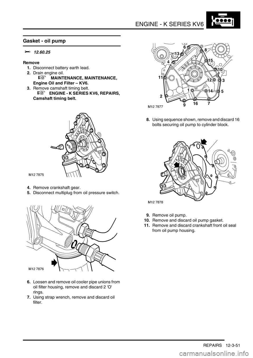
6.Loosen and remove oil cooler pipe unions from
oil filter housing, remove and discard 2 'O'
rings.
7.Using strap wrench, remove and discard oil
filter.8.Using sequence shown, remove and discard 16
bolts securing oil pump to cylinder block.
9.Remove oil pump.
10.Remove and discard oil pump gasket.
11.Remove and discard crankshaft front oil seal
from oil pump housing.
Page 229 of 1007
ENGINE - K SERIES KV6
12-3-52 REPAIRS
Refit
1.Clean oil pump and mating face on cylinder
block ensure bolt holes are clean and dry.
2.Clean oil seal recess in oil pump and running
surface on crankshaft.
3.Fit new oil pump gasket, dry, to cylinder block.
4.Fit oil seal guide, from seal kit, over end of
crankshaft.
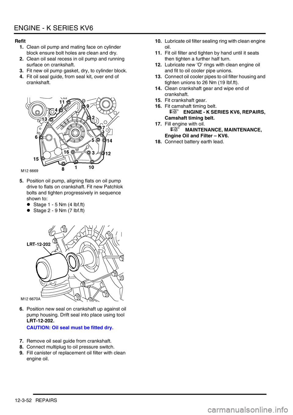
5.Position oil pump, aligning flats on oil pump
drive to flats on crankshaft. Fit new Patchlok
bolts and tighten progressively in sequence
shown to:
lStage 1 - 5 Nm (4 lbf.ft)
lStage 2 - 9 Nm (7 lbf.ft)
6.Position new seal on crankshaft up against oil
pump housing. Drift seal into place using tool
LRT-12-202.
CAUTION: Oil seal must be fitted dry.
7.Remove oil seal guide from crankshaft.
8.Connect multiplug to oil pressure switch.
9.Fill canister of replacement oil filter with clean
engine oil.10.Lubricate oil filter sealing ring with clean engine
oil.
11.Fit oil filter and tighten by hand until it seats
then tighten a further half turn.
12.Lubricate new 'O' rings with clean engine oil
and fit to oil cooler pipe unions.
13.Connect oil cooler pipes to oil filter housing and
tighten unions to 26 Nm (19 lbf.ft).
14.Clean crankshaft gear and wipe end of
crankshaft.
15.Fit crankshaft gear.
16.Fit camshaft timing belt.
+ ENGINE - K SERIES KV6, REPAIRS,
Camshaft timing belt.
17.Fill engine with oil.
+ MAINTENANCE, MAINTENANCE,
Engine Oil and Filter – KV6.
18.Connect battery earth lead.
Page 230 of 1007
ENGINE - K SERIES KV6
REPAIRS 12-3-53
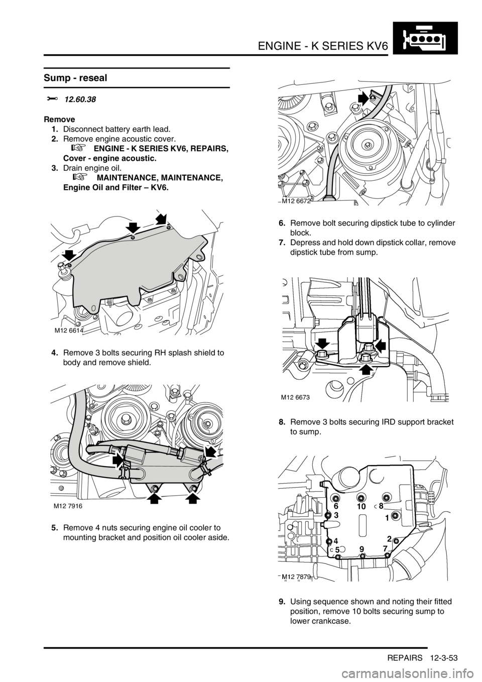
Sump - reseal
$% 12.60.38
Remove
1.Disconnect battery earth lead.
2.Remove engine acoustic cover.
+ ENGINE - K SERIES KV6, REPAIRS,
Cover - engine acoustic.
3.Drain engine oil.
+ MAINTENANCE, MAINTENANCE,
Engine Oil and Filter – KV6.
4.Remove 3 bolts securing RH splash shield to
body and remove shield.
5.Remove 4 nuts securing engine oil cooler to
mounting bracket and position oil cooler aside.6.Remove bolt securing dipstick tube to cylinder
block.
7.Depress and hold down dipstick collar, remove
dipstick tube from sump.
8.Remove 3 bolts securing IRD support bracket
to sump.
9.Using sequence shown and noting their fitted
position, remove 10 bolts securing sump to
lower crankcase.
M12 6614
M12 7916
M12 6672