LAND ROVER FREELANDER 2001 Manual Online
Manufacturer: LAND ROVER, Model Year: 2001, Model line: FREELANDER, Model: LAND ROVER FREELANDER 2001Pages: 1007, PDF Size: 23.47 MB
Page 81 of 1007
GENERAL DATA
04-18
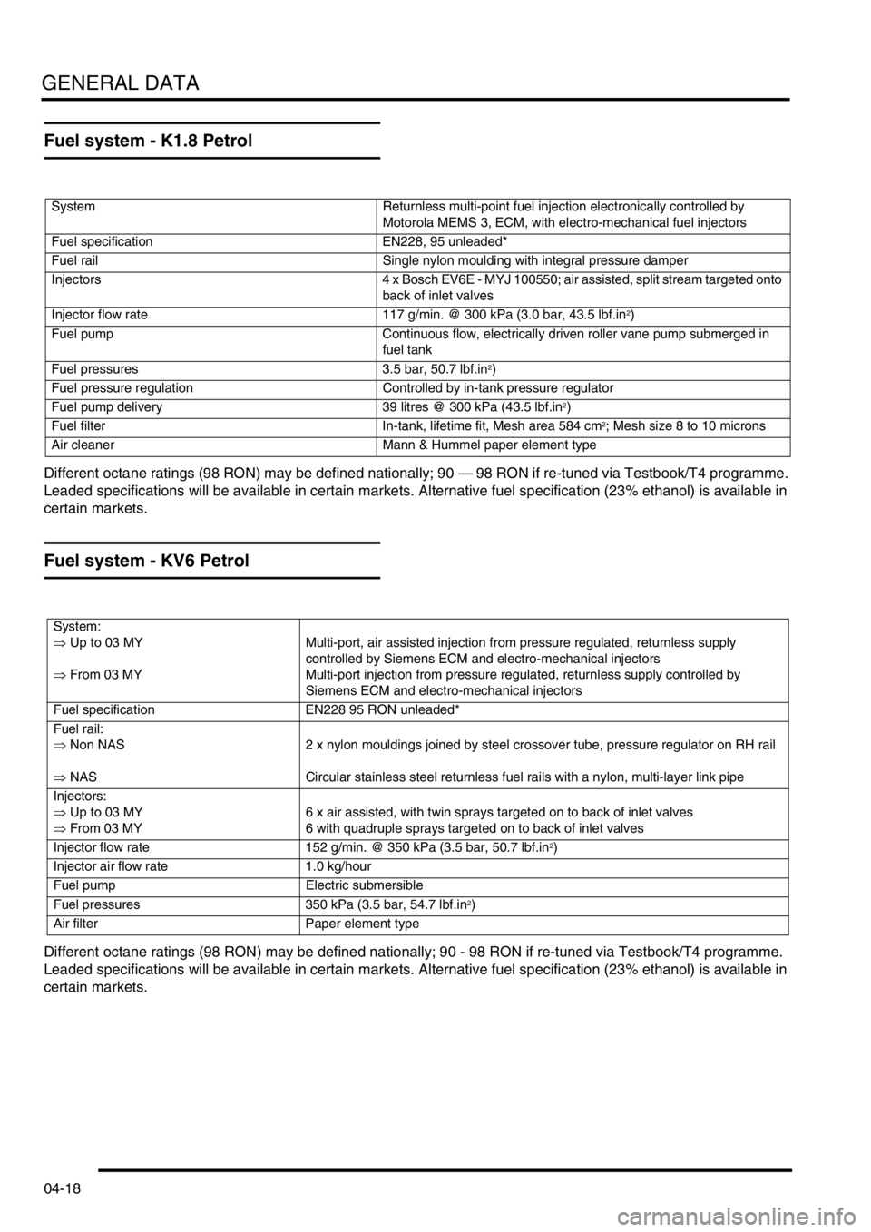
Fuel system - K1.8 Petrol
Different octane ratings (98 RON) may be defined nationally; 90 — 98 RON if re-tuned via Testbook/T4 programme.
Leaded specifications will be available in certain markets. Alternative fuel specification (23% ethanol) is available in
certain markets.
Fuel system - KV6 Petrol
Different octane ratings (98 RON) may be defined nationally; 90 - 98 RON if re-tuned via Testbook/T4 programme.
Leaded specifications will be available in certain markets. Alternative fuel specification (23% ethanol) is available in
certain markets.
System Returnless multi-point fuel injection electronically controlled by
Motorola MEMS 3, ECM, with electro-mechanical fuel injectors
Fuel specification EN228, 95 unleaded*
Fuel rail Single nylon moulding with integral pressure damper
Injectors 4 x Bosch EV6E - MYJ 100550; air assisted, split stream targeted onto
back of inlet valves
Injector flow rate 117 g/min. @ 300 kPa (3.0 bar, 43.5 lbf.in
2)
Fuel pump Continuous flow, electrically driven roller vane pump submerged in
fuel tank
Fuel pressures 3.5 bar, 50.7 lbf.in
2)
Fuel pressure regulation Controlled by in-tank pressure regulator
Fuel pump delivery 39 litres @ 300 kPa (43.5 lbf.in
2)
Fuel filter In-tank, lifetime fit, Mesh area 584 cm
2; Mesh size 8 to 10 microns
Air cleaner Mann & Hummel paper element type
System:
⇒ Up to 03 MY
⇒ From 03 MYMulti-port, air assisted injection from pressure regulated, returnless supply
controlled by Siemens ECM and electro-mechanical injectors
Multi-port injection from pressure regulated, returnless supply controlled by
Siemens ECM and electro-mechanical injectors
Fuel specification EN228 95 RON unleaded*
Fuel rail:
⇒ Non NAS
⇒ NAS2 x nylon mouldings joined by steel crossover tube, pressure regulator on RH rail
Circular stainless steel returnless fuel rails with a nylon, multi-layer link pipe
Injectors:
⇒ Up to 03 MY
⇒ From 03 MY6 x air assisted, with twin sprays targeted on to back of inlet valves
6 with quadruple sprays targeted on to back of inlet valves
Injector flow rate 152 g/min. @ 350 kPa (3.5 bar, 50.7 lbf.in
2)
Injector air flow rate 1.0 kg/hour
Fuel pump Electric submersible
Fuel pressures 350 kPa (3.5 bar, 54.7 lbf.in
2)
Air filter Paper element type
Page 82 of 1007
GENERAL DATA
04-19
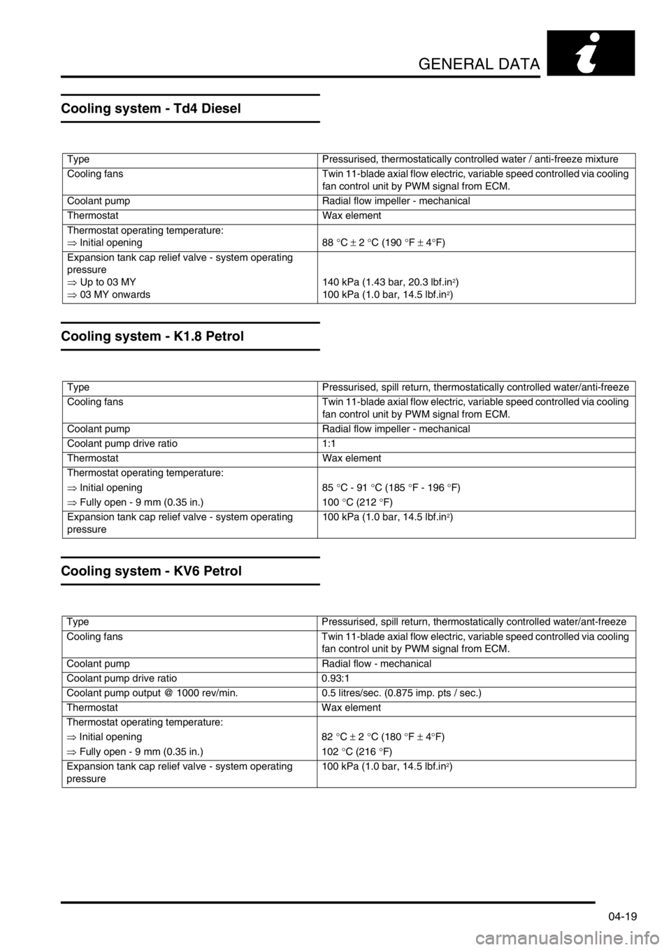
Cooling system - Td4 Diesel
Cooling system - K1.8 Petrol
Cooling system - KV6 Petrol
Type Pressurised, thermostatically controlled water / anti-freeze mixture
Cooling fans Twin 11-blade axial flow electric, variable speed controlled via cooling
fan control unit by PWM signal from ECM.
Coolant pump Radial flow impeller - mechanical
Thermostat Wax element
Thermostat operating temperature:
⇒ Initial opening 88 °C ± 2 °C (190 °F ± 4°F)
Expansion tank cap relief valve - system operating
pressure
⇒ Up to 03 MY
⇒ 03 MY onwards140 kPa (1.43 bar, 20.3 lbf.in
2)
100 kPa (1.0 bar, 14.5 lbf.in2)
Type Pressurised, spill return, thermostatically controlled water/anti-freeze
Cooling fans Twin 11-blade axial flow electric, variable speed controlled via cooling
fan control unit by PWM signal from ECM.
Coolant pump Radial flow impeller - mechanical
Coolant pump drive ratio 1:1
Thermostat Wax element
Thermostat operating temperature:
⇒ Initial opening 85 °C - 91 °C (185 °F - 196 °F)
⇒ Fully open - 9 mm (0.35 in.) 100 °C (212 °F)
Expansion tank cap relief valve - system operating
pressure100 kPa (1.0 bar, 14.5 lbf.in
2)
Type Pressurised, spill return, thermostatically controlled water/ant-freeze
Cooling fans Twin 11-blade axial flow electric, variable speed controlled via cooling
fan control unit by PWM signal from ECM.
Coolant pump Radial flow - mechanical
Coolant pump drive ratio 0.93:1
Coolant pump output @ 1000 rev/min. 0.5 litres/sec. (0.875 imp. pts / sec.)
Thermostat Wax element
Thermostat operating temperature:
⇒ Initial opening 82 °C ± 2 °C (180 °F ± 4°F)
⇒ Fully open - 9 mm (0.35 in.) 102 °C (216 °F)
Expansion tank cap relief valve - system operating
pressure100 kPa (1.0 bar, 14.5 lbf.in
2)
Page 83 of 1007
GENERAL DATA
04-20
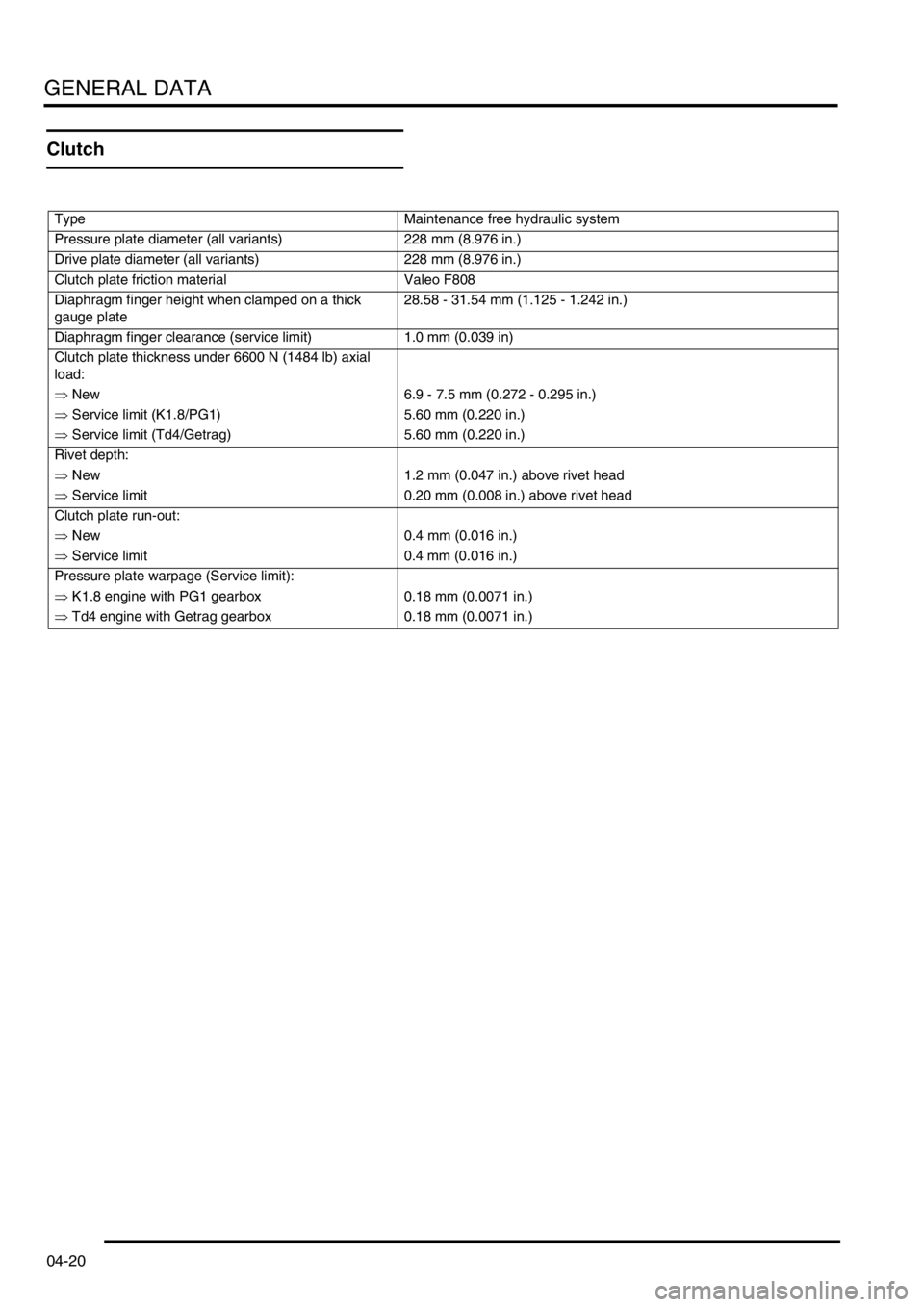
Clutch
Type Maintenance free hydraulic system
Pressure plate diameter (all variants) 228 mm (8.976 in.)
Drive plate diameter (all variants) 228 mm (8.976 in.)
Clutch plate friction material Valeo F808
Diaphragm finger height when clamped on a thick
gauge plate28.58 - 31.54 mm (1.125 - 1.242 in.)
Diaphragm finger clearance (service limit) 1.0 mm (0.039 in)
Clutch plate thickness under 6600 N (1484 lb) axial
load:
⇒ New 6.9 - 7.5 mm (0.272 - 0.295 in.)
⇒ Service limit (K1.8/PG1) 5.60 mm (0.220 in.)
⇒ Service limit (Td4/Getrag) 5.60 mm (0.220 in.)
Rivet depth:
⇒ New 1.2 mm (0.047 in.) above rivet head
⇒ Service limit 0.20 mm (0.008 in.) above rivet head
Clutch plate run-out:
⇒ New 0.4 mm (0.016 in.)
⇒ Service limit 0.4 mm (0.016 in.)
Pressure plate warpage (Service limit):
⇒ K1.8 engine with PG1 gearbox 0.18 mm (0.0071 in.)
⇒ Td4 engine with Getrag gearbox 0.18 mm (0.0071 in.)
Page 84 of 1007
GENERAL DATA
04-21
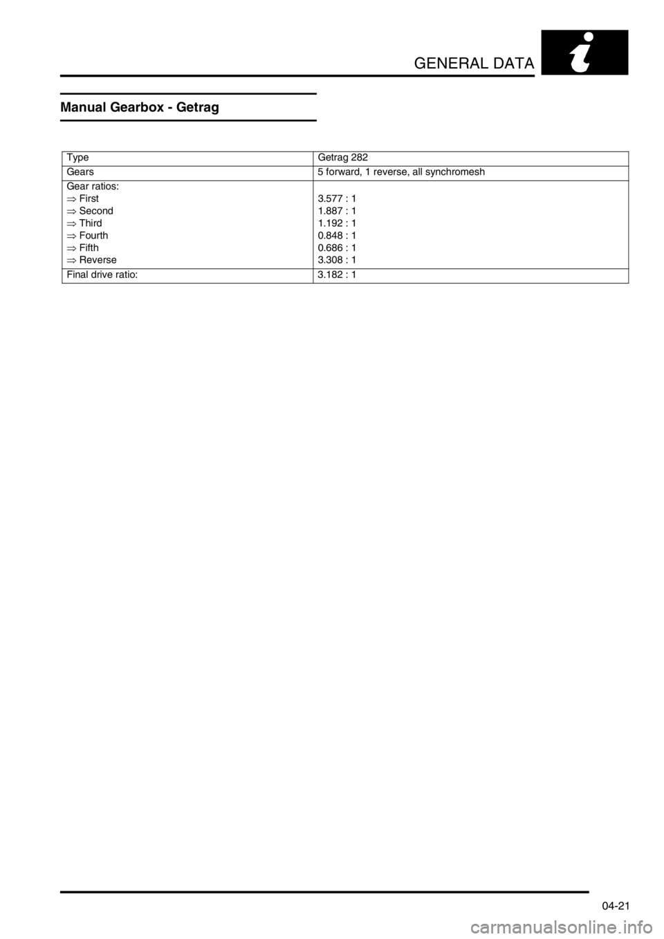
Manual Gearbox - Getrag
Type Getrag 282
Gears 5 forward, 1 reverse, all synchromesh
Gear ratios:
⇒ First
⇒ Second
⇒ Third
⇒ Fourth
⇒ Fifth
⇒ Reverse3.577 : 1
1.887 : 1
1.192 : 1
0.848 : 1
0.686 : 1
3.308 : 1
Final drive ratio: 3.182 : 1
Page 85 of 1007
GENERAL DATA
04-22
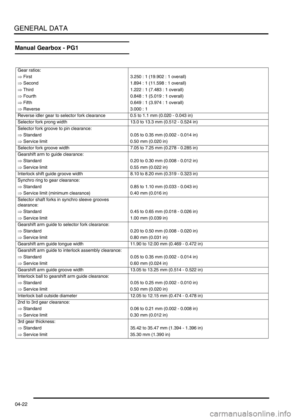
Manual Gearbox - PG1
Gear ratios:
⇒ First 3.250 : 1 (19.902 : 1 overall)
⇒ Second 1.894 : 1 (11.598 : 1 overall)
⇒ Third 1.222 : 1 (7.483 : 1 overall)
⇒ Fourth 0.848 : 1 (5.019 : 1 overall)
⇒ Fifth 0.649 : 1 (3.974 : 1 overall)
⇒ Reverse 3.000 : 1
Reverse idler gear to selector fork clearance 0.5 to 1.1 mm (0.020 - 0.043 in)
Selector fork prong width 13.0 to 13.3 mm (0.512 - 0.524 in)
Selector fork groove to pin clearance:
⇒ Standard 0.05 to 0.35 mm (0.002 - 0.014 in)
⇒ Service limit 0.50 mm (0.020 in)
Selector fork groove width 7.05 to 7.25 mm (0.278 - 0.285 in)
Gearshift arm to guide clearance:
⇒ Standard 0.20 to 0.30 mm (0.008 - 0.012 in)
⇒ Service limit 0.55 mm (0.022 in)
Interlock shift guide groove width 8.10 to 8.20 mm (0.319 - 0.323 in)
Synchro ring to gear clearance:
⇒ Standard 0.85 to 1.10 mm (0.033 - 0.043 in)
⇒ Service limit (minimum clearance) 0.40 mm (0.016 in)
Selector shaft forks in synchro sleeve grooves
clearance:
⇒ Standard 0.45 to 0.65 mm (0.018 - 0.026 in)
⇒ Service limit 1.00 mm (0.039 in)
Gearshift arm guide to selector fork clearance:
⇒ Standard 0.20 to 0.50 mm (0.008 - 0.020 in)
⇒ Service limit 0.80 mm (0.031 in)
Gearshift arm guide tongue width 11.90 to 12.00 mm (0.469 - 0.472 in)
Gearshift arm guide to interlock assembly clearance:
⇒ Standard 0.05 to 0.35 mm (0.002 - 0.014 in)
⇒ Service limit 0.60 mm (0.024 in)
Gearshift arm guide groove width 13.05 to 13.25 mm (0.514 - 0.522 in)
Interlock ball to gearshift arm guide clearance:
⇒ Standard 0.05 to 0.25 mm (0.002 - 0.010 in)
⇒ Service limit 0.50 mm (0.020 in)
Interlock ball outside diameter 12.05 to 12.15 mm (0.474 - 0.478 in)
2nd to 3rd gear clearance:
⇒ Standard 0.06 to 0.21 mm (0.002 - 0.008 in)
⇒ Service limit 0.30 mm (0.012 in)
3rd gear thickness:
⇒ Standard 35.42 to 35.47 mm (1.394 - 1.396 in)
⇒ Service limit 35.30 mm (1.390 in)
Page 86 of 1007

GENERAL DATA
04-23
4th to 5th gear clearance:
⇒ Standard 0.06 to 0.21 mm (0.002 - 0.008 in)
⇒ Service limit 0.30 mm (0.012 in)
Spacer collar length:
⇒ Standard 26.03 to 26.08 mm (1.025 - 1.027 in)
⇒ Service limit 26.01 mm (1.024 in)
4th gear thickness:
⇒ Standard 30.92 to 30.97 mm (1.217 - 1.219 in)
⇒ Service limit 30.80 mm (1.213 in)
5th gear thickness:
⇒ Standard 30.42 to 30.47 mm (1.198 - 1.200 in)
⇒ Service limit 30.30 mm (1.193 in)
1st. gear to thrust washer clearance:
⇒ Standard 0.03 to 0.08 mm (0.0012 - 0.0031 in)
⇒ Service limit 0.18 mm (0.007 in)
2nd to 3rd gear clearance 0.03 to 0.10 mm (0.0012 - 0.0039 in)
Input shaft end thrust 0.14 to 0.21 mm (0.006 - 0.008 in)
Page 87 of 1007
GENERAL DATA
04-24
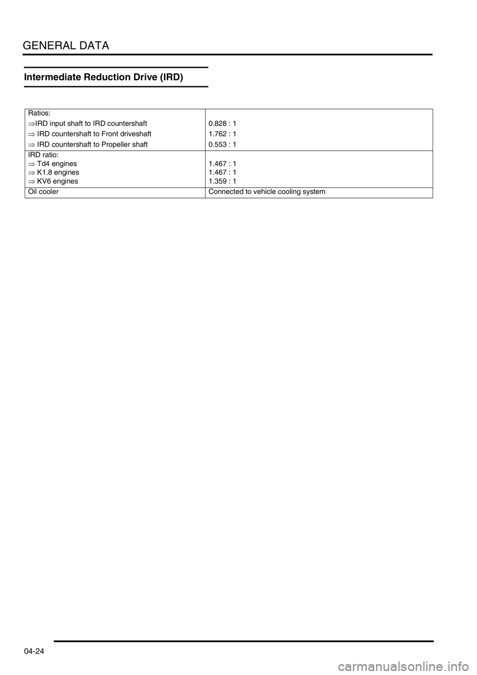
Intermediate Reduction Drive (IRD)
Ratios:
⇒IRD input shaft to IRD countershaft 0.828 : 1
⇒ IRD countershaft to Front driveshaft 1.762 : 1
⇒ IRD countershaft to Propeller shaft 0.553 : 1
IRD ratio:
⇒ Td4 engines
⇒ K1.8 engines
⇒ KV6 engines1.467 : 1
1.467 : 1
1.359 : 1
Oil cooler Connected to vehicle cooling system
Page 88 of 1007
GENERAL DATA
04-25
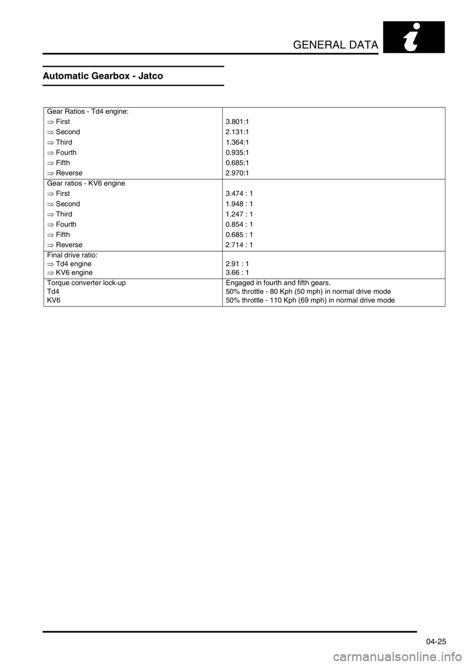
Automatic Gearbox - Jatco
Gear Ratios - Td4 engine:
⇒ First 3.801:1
⇒ Second 2.131:1
⇒ Third 1.364:1
⇒ Fourth 0.935:1
⇒ Fifth 0.685:1
⇒ Reverse 2.970:1
Gear ratios - KV6 engine
⇒ First 3.474 : 1
⇒ Second 1.948 : 1
⇒ Third 1.247 : 1
⇒ Fourth 0.854 : 1
⇒ Fifth 0.685 : 1
⇒ Reverse 2.714 : 1
Final drive ratio:
⇒ Td4 engine
⇒ KV6 engine2.91 : 1
3.66 : 1
Torque converter lock-up
Td4
KV6Engaged in fourth and fifth gears.
50% throttle - 80 Kph (50 mph) in normal drive mode
50% throttle - 110 Kph (69 mph) in normal drive mode
Page 89 of 1007
GENERAL DATA
04-26
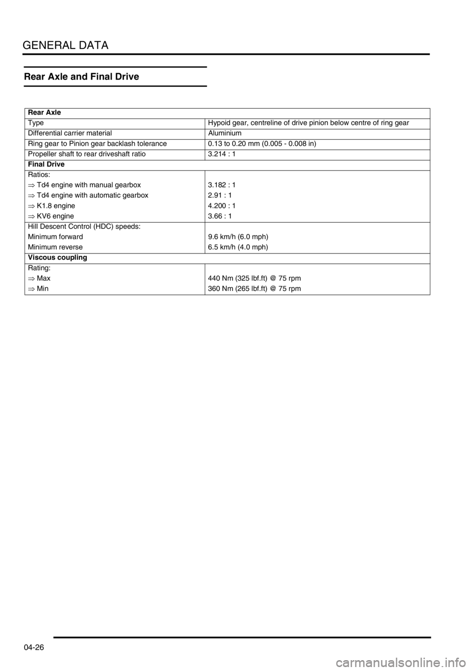
Rear Axle and Final Drive
Rear Axle
Type Hypoid gear, centreline of drive pinion below centre of ring gear
Differential carrier material Aluminium
Ring gear to Pinion gear backlash tolerance 0.13 to 0.20 mm (0.005 - 0.008 in)
Propeller shaft to rear driveshaft ratio 3.214 : 1
Final Drive
Ratios:
⇒ Td4 engine with manual gearbox 3.182 : 1
⇒ Td4 engine with automatic gearbox 2.91 : 1
⇒ K1.8 engine 4.200 : 1
⇒ KV6 engine 3.66 : 1
Hill Descent Control (HDC) speeds:
Minimum forward 9.6 km/h (6.0 mph)
Minimum reverse 6.5 km/h (4.0 mph)
Viscous coupling
Rating:
⇒ Max 440 Nm (325 lbf.ft) @ 75 rpm
⇒ Min 360 Nm (265 lbf.ft) @ 75 rpm
Page 90 of 1007
GENERAL DATA
04-27
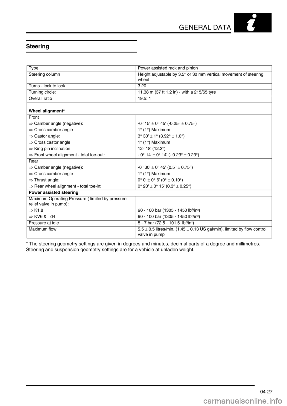
Steering
* The steering geometry settings are given in degrees and minutes, decimal parts of a degree and millimetres.
Steering and suspension geometry settings are for a vehicle at unladen weight.
Type Power assisted rack and pinion
Steering column Height adjustable by 3.5° or 30 mm vertical movement of steering
wheel
Turns - lock to lock 3.20
Turning circle: 11.38 m (37 ft 1.2 in) - with a 215/65 tyre
Overall ratio 19.5: 1
Wheel alignment*
Front
⇒ Camber angle (negative): -0° 15' ± 0° 45' (-0.25° ± 0.75°)
⇒ Cross camber angle 1° (1°) Maximum
⇒ Castor angle: 3° 30' ± 1° (3.92° ± 1.0°)
⇒ Cross castor angle 1° (1°) Maximum
⇒ King pin inclination 12° 18' (12.3°)
⇒ Front wheel alignment - total toe-out: - 0° 14' ± 0° 14' (- 0.23° ± 0.23°)
Rear
⇒ Camber angle (negative): -0° 30' ± 0° 45' (0.5° ± 0.75°)
⇒ Cross camber angle 1° (1°) Maximum
⇒ Thrust angle: 0° 0' ± 0° 6' (0° ± 0.10°)
⇒ Rear wheel alignment - total toe-in: 0° 20' ± 0° 15' (0.3° ± 0.25°)
Power assisted steering
Maximum Operating Pressure ( limited by pressure
relief valve in pump):
⇒ K1.8 90 - 100 bar (1305 - 1450 lbf/in
2)
⇒ KV6 & Td4 90 - 100 bar (1305 - 1450 lbf/in
2)
Pressure at idle 5 - 7 bar (72.5 - 101.5 lbf/in
2)
Maximum flow 5.5 ± 0.5 litres/min. (1.45 ± 0.13 US gal/min), limited by flow control
valve in pump