LAND ROVER FRELANDER 2 2006 Repair Manual
FRELANDER 2 2006
LAND ROVER
LAND ROVER
https://www.carmanualsonline.info/img/64/57251/w960_57251-0.png
LAND ROVER FRELANDER 2 2006 Repair Manual
Trending: fuse, cabin filter, heating, trip computer, fog light, wipers, lumbar support
Page 1461 of 3229
Publi s hed: 11-May-2011
Manual Transmission/Transaxle - Transmission
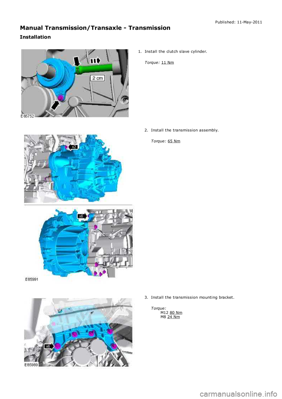
Installation Ins t al l the cl ut ch s lave cylinder.
T orque: 11 Nm 1.
Inst all t he transmis si on as sembl y.
T orque: 65 Nm 2.
Inst all t he transmis si on mounti ng bracket .
T orque: M12 80 Nm M8
24 Nm 3.
Page 1462 of 3229
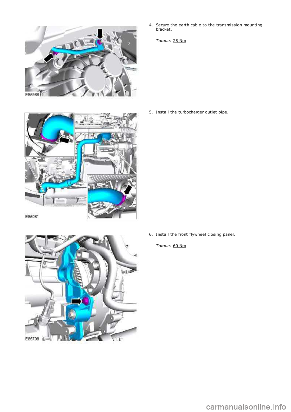
Secure t he eart h cabl e t o t he trans mi s si on mounti ng
bracket.
T orque: 25 Nm 4.
Inst all t he turbocharger outl et pi pe.
5. Inst all t he front flywheel cl osi ng panel .
T orque: 60 Nm 6.
Page 1463 of 3229
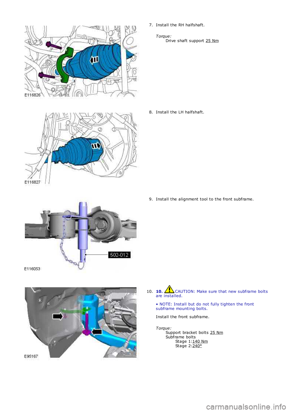
St age 1:
St age 2: Inst all t he RH halfs haft.
T orque: Dri ve s haft s upport 25 Nm 7.
Inst all t he LH halfshaft.
8. Inst all t he alignment t ool t o t he front subframe.
9. 10. CAUTION: Make s ure t hat new s ubframe bolt s
are ins tal led.
• NOTE: Inst all but do not ful ly t ighten the front
s ubframe mounti ng bolt s.
Inst all t he front subframe.
T orque: Support bracket bolt s 25 Nm Subframe bol ts
140 Nm 240°10.
Page 1464 of 3229
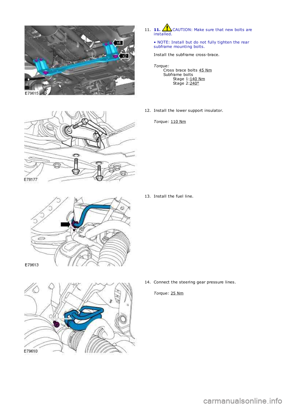
St age 1:
St age 2: 11. CAUTION: Make s ure t hat new bolt s are
i ns t alled.
• NOTE: Inst all but do not ful ly t ighten the rear
s ubframe mounti ng bolt s.
Inst all t he s ubframe cross -brace.
T orque: Cros s brace bolt s 45 Nm Subframe bol ts
140 Nm 240°11.
Inst all t he lower s upport ins ul ator.
T orque: 110 Nm 12.
Inst all t he fuel li ne.
13. Connect t he s teeri ng gear press ure li nes .
T orque: 25 Nm 14.
Page 1465 of 3229
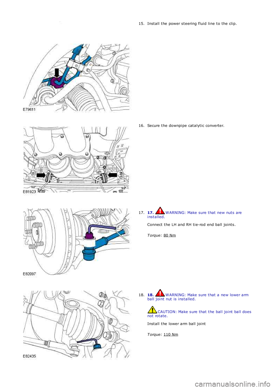
Inst all t he power s t eering flui d li ne t o the cl ip.
15. Secure t he downpi pe cat alyt ic converter.
16. 17. W ARNING: Make sure t hat new nut s are
i ns t alled.
Connect t he LH and RH ti e-rod end bal l joint s .
T orque: 80 Nm 17.
18. W ARNING: Make sure t hat a new lower arm
ball joi nt nut is i ns t alled. CAUTION: Make s ure that t he bal l joi nt bal l does
not rot ate.
Inst all t he lower arm ball joi nt
T orque: 110 Nm 18.
Page 1466 of 3229
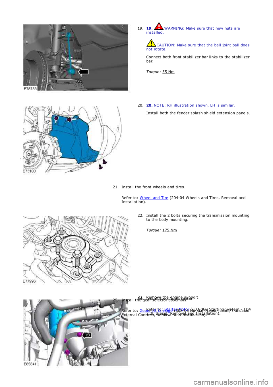
19. W ARNING: Make sure t hat new nut s are
i ns t alled. CAUTION: Make s ure that t he bal l joi nt bal l does
not rot ate.
Connect both front s t abi li zer bar li nks to the s t abi li zer
bar.
T orque: 55 Nm 19.
20.
NOTE: RH i llus t rati on s hown, LH is s imil ar.
Inst all both the fender s plas h s hield ext ensi on panel s.
20.
Inst all t he front wheel s and ti res .
Refer t o: W heel and Ti re (204-04 W heel s and Tires, Removal and
Inst all at ion).
21. Inst all t he 2 bolt s s ecuring t he t ransmis s ion mount ing
t o t he body mount ing.
T orque: 175 Nm 22.
Remove t he engi ne s upport .
23. Inst all t he s tart er mot or.
Refer t o: Start er Motor (303-06B Starti ng Sys t em - TD4
2.2L Dies el , Removal and Inst all at ion).
24.
Inst all t he gear s elector as s embl y.
Refer t o: Gears hi ft Li nkage (308-06 Manual Trans mi s si on/Trans axl e
External Controls , Removal and Inst all at ion).
25.
Page 1467 of 3229
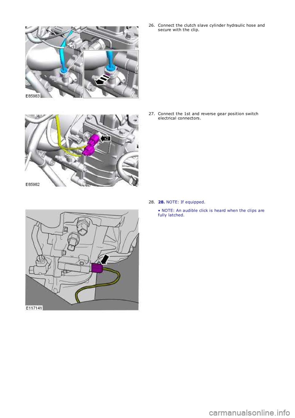
Connect t he clutch s l ave cyli nder hydrauli c hos e ands ecure wi th t he cli p.26.
Connect t he 1st and revers e gear pos it ion swi tchelectrical connect ors .27.
28. NOTE: If equipped.
• NOTE: An audibl e click i s heard when t he cli ps areful ly latched.
28.
Page 1468 of 3229
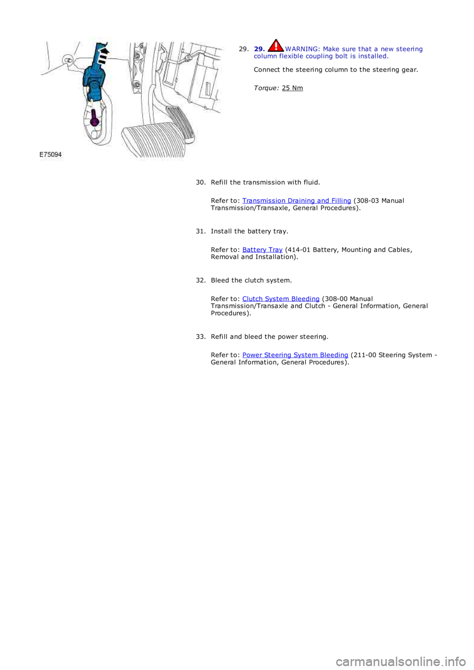
29. W ARNING: Make sure t hat a new s teeri ng
column flexibl e coupl ing bolt i s ins t al led.
Connect t he s teeri ng col umn t o t he s teeri ng gear.
T orque: 25 Nm 29.
Refi ll t he transmis s ion wi th flui d.
Refer t o: Transmis s ion Draining and Fi lli ng (308-03 Manual
Trans mi ss ion/Transaxle, General Procedures).
30.
Inst all t he bat t ery t ray.
Refer t o: Bat t ery Tray (414-01 Bat tery, Mount ing and Cables ,
Removal and Ins tall ati on).
31.
Bleed t he clut ch sys t em.
Refer t o: Clutch Sys tem Bleeding (308-00 Manual
Trans mi ss ion/Transaxle and Clut ch - General Informati on, General
Procedures ).
32.
Refi ll and bleed t he power st eeri ng.
Refer t o: Power St eering Sys tem Bleeding (211-00 St eering Sys tem -
General Informat ion, General Procedures ).
33.
Page 1469 of 3229
Publi s hed: 11-May-2011
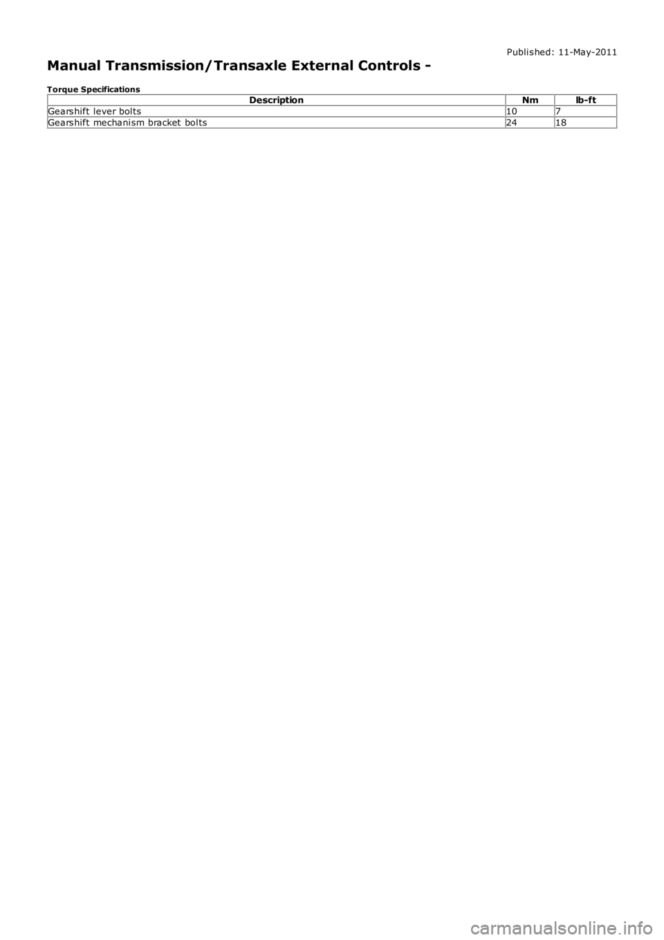
Manual Transmission/Transaxle External Controls -
Torque SpecificationsDescriptionNmlb-ft
Gears hift lever bol ts107
Gears hift mechani sm bracket bol ts2418
Page 1470 of 3229
Publi s hed: 11-May-2011
Manual Transmission/Transaxle External Controls - External Controls
Des cript ion and Operat ion
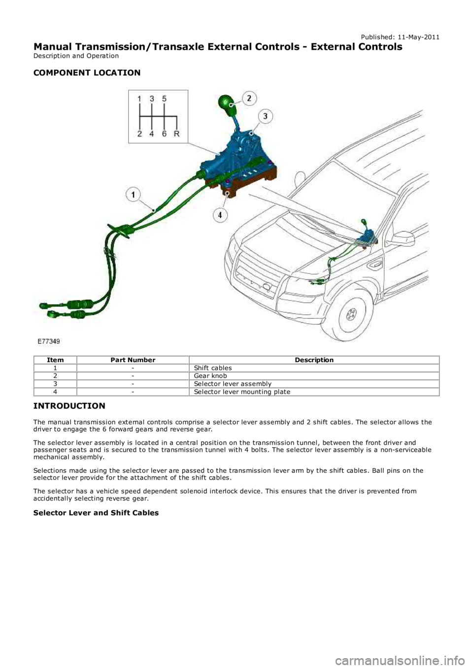
COMPONENT LOCATION
ItemPart NumberDescription
1-Shi ft cables2-Gear knob
3-Sel ect or lever as s embly
4-Sel ect or lever mount ing pl at e
INTRODUCTION
The manual t rans mi ss i on ext ernal cont rols compris e a sel ect or lever as s embly and 2 shi ft cables . The sel ect or al lows t hedri ver t o engage the 6 forward gears and revers e gear.
The s elect or lever ass embly is l ocat ed in a cent ral posi ti on on t he t ransmis s ion t unnel , bet ween the front driver andpass enger s eats and is s ecured t o t he transmis si on t unnel wit h 4 bol ts . The s elector lever ass embly is a non-s erviceabl emechani cal as sembl y.
Selecti ons made usi ng the sel ect or lever are pass ed t o t he t rans mis s ion l ever arm by t he s hift cables . Ball pins on thes elect or lever provide for the at tachment of t he s hift cabl es .
The s elect or has a vehicle s peed dependent sol enoi d int erl ock device. Thi s ensures that t he dri ver i s prevent ed fromacci dent al ly sel ect ing reverse gear.
Selector Lever and Shift Cables
Trending: mirror, fuel filter, CD changer, alarm, battery capacity, headrest, brake fluid
