LAND ROVER FRELANDER 2 2006 Repair Manual
Manufacturer: LAND ROVER, Model Year: 2006, Model line: FRELANDER 2, Model: LAND ROVER FRELANDER 2 2006Pages: 3229, PDF Size: 78.5 MB
Page 2161 of 3229
(Ignit ion). The forward facing light s ensor moni tors the ambi ent light l evel at the front of t he vehi cl e; the rearward facingli ght sens or moni tors t he li ght l evel coming from t he rear of the vehicle. W hen li ght from the rear of the vehicle exceedst he ambient li ght l evel from the front of t he vehi cl e, the aut omat ic di mmi ng circuit darkens t he i nt eri or mirror s urface.
Automat ic di mmi ng is i nhi bit ed when revers e gear is sel ect ed to provide t he dri ver wi th maximum vis ion. On vehicles wi thautomat ic t rans mis s ion, t he revers e gear s ignal i s provided by t he TCM vi a t he high s peed Cont rol ler Area Net work (CAN)bus to the CJB. The CJB then provi des a power feed t o t he mirror. On vehicles wi th manual t rans mis s ion, the revers e gears ignal is provi ded by a t ransmis s ion s wit ch t hat i s hardwi red t o t he CJB.
Cabin Humidity Sensor
Dependi ng on the vehicl e s pecificati on, t he automat ic di mmi ng int erior mirror may als o i ncorporate a cabi n humidi tys ens or. The cabin humi dit y s ens or is locat ed i n the mirror rear cas ing near to the wi nds hiel d, and provi des the ATC modul ewit h i nformati on regarding the probabil it y of winds hield mis t ing. Thi s i nformat ion is us ed to vary t he automat ic operat ionof the cl imat e cont rol s yst em.For addit ional informat ion, refer t o: Cont rol Component s (412-01 Cli mat e Cont rol , Descripti on and Operat ion).
EXTERIOR MIRRORS
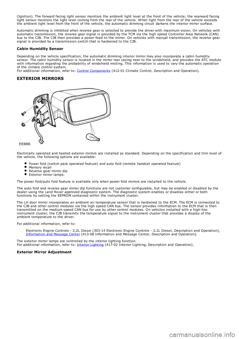
Electricall y operated and heated ext eri or mirrors are i nst all ed as s tandard. Depending on the s pecifi cat ion and trim level oft he vehi cl e, t he followi ng opti ons are available:
Power fold (s wit ch pack operat ed feat ure) and auto fol d (remote hands et operated feature)Memory recallRevers e gear mirror dipExteri or mirror l amps.
The power fold/aut o fold feature is avail abl e only when power fol d mi rrors are i ns t alled to t he vehicle.
The auto fold and revers e gear mirror dip functi ons are not cus t omer confi gurable, but may be enabled or dis abled by t hedeal er usi ng the Land Rover approved di agnos ti c s ys t em. The diagnos t ic s ys tem enabl es or di sabl es ei ther or bothfuncti ons by s et t ing t he EEPROM cont ained wi thin the ins trument cl us t er.
The LH door mirror i ncorporat es an ambi ent ai r temperat ure sens or that is hardwired to the ECM. The ECM is connected tot he CJB and ot her cont rol modules via the hi gh s peed CAN bus . The s ensor provides i nformati on to the ECM that is thent ransmit ted on the medi um s peed CAN bus for us e by ot her control modul es. O n vehi cl es ins tal led wi th a high-lineins t rument clus ter, t he CJB t rans mit s t he temperature s ignal t o t he ins t rument clus ter t hat provi des a dis play of t heambient t emperature t o the driver.
For addit ional informat ion, refer t o:
Elect roni c Engi ne Cont rol s - 2.2L Dies el (303-14 Electronic Engine Controls - 2.2L Dies el, Des cript ion and Operat ion),Informat ion and Mes s age Cent er (413-08 Informati on and Mes sage Cent er, Descripti on and Operat ion).
The exteri or mirror l amps are controll ed by the interior li ght ing funct ion.For addit ional informat ion, refer t o: Int eri or Li ght ing (417-02 Interior Lighti ng, Des cri pt ion and Operati on).
Exterior Mirror Adjustment
Page 2162 of 3229
ItemPart NumberDescription
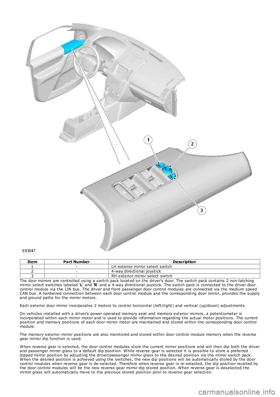
1-LH ext eri or mirror s el ect s wi tch2-4-way direct ional joyst ick
3-RH ext eri or mirror s elect swi tch
The door mirrors are controlled us i ng a s wit ch pack locat ed on t he dri ver's door. The s wi tch pack cont ains 2 non-l atchingmi rror s elect s wit ches l abel ed 'L' and 'R' and a 4-way direct ional joys ti ck. The s wit ch pack i s connected to t he driver doorcont rol module vi a t he LIN bus . The dri ver and front pas senger door control modul es are connect ed vi a t he medium s peedCAN bus . A hardwi red connect ion between each door cont rol module and t he corres ponding door mirror, provi des the supplyand ground paths for the mirror mot ors .
Each ext eri or door mi rror i ncorporates 2 motors to cont rol hori zont al (left/ri ght ) and vert ical (up/down) adjus tment s .
On vehicles i nst all ed wit h a driver's power operat ed memory s eat and memory ext erior mi rrors , a pot ent iomet er isincorporat ed wit hin each mirror motor and i s us ed to provide i nformat ion regarding the actual motor pos it ions . The currentposi ti on and memory posi ti ons of each door mirror mot or are mai ntained and s t ored withi n t he corres pondi ng door controlmodule.
The memory ext eri or mirror pos it ions are al s o monit ored and s t ored wi thin door control modul e memory when t he revers egear mirror dip funct ion is us ed.
W hen revers e gear i s s elected, the door cont rol modules s t ore t he current mirror posi ti ons and wil l then dip bot h t he dri verand pass enger mirror glas s t o a defaul t di p pos it ion. W hil e reverse gear i s s el ect ed it is pos si ble t o s t ore a preferreddipped mi rror pos it ion by adjust ing the driver/pas s enger mi rror glas s to the des ired posi ti on via t he mi rror swit ch pack.W hen t he des ired pos it ion is achieved usi ng t he swit ches , the new di p pos it ions wil l be automat ically st ored by the doorcont rol modules when revers e gear i s de-s elected. Therefore when reverse gear i s re-s el ect ed, the di p posi ti on recall ed byt he door control modul es wil l be the new revers e gear mirror dip st ored pos it ion. W hen revers e gear i s des el ect ed t hemi rror gl ass will aut omati call y move t o t he previous s t ored posi ti on pri or to reverse gear sel ect ion.
Page 2163 of 3229
Revers e gear mirror dip i s only avail abl e when memory mi rrors are ins t al led, and revers e gear mi rror di p is enabled wit hint he ins trument cl ust er.
If the driver sel ect s a memory recall funct ion us ing the memory s eat swit ch pack, the driver's memory seat and exteriormemory mi rrors are moved to a s tored memory pos i ti on.For addit ional informat ion, refer t o: Seat s (501-10 Seati ng, Des cript ion and Operat ion).
Mirror Power Fold and Auto Fold Feature
Exteri or mirrors wit h t he power fold/auto fold feature incorporat e a motor located in t he hinge of each ext eri or mirror arm.Operat ion of t he power fold feature is achieved us ing t he exteri or mirror s wit ch pack. Operat ion of t he auto fold feature isachi eved us ing the remote hands et.
The power fold funct ion is acti ve when t he ignit ion i s in power mode 6 (Ignit ion).
Both ext eri or mirrors wil l power fol d when t he mi rror s wi tch pack 'L' and 'R' s wit ches are pres s ed t oget her. Pres s ing t hes wit ches again wil l unfol d t he mi rrors .
W hen t he i ns t rument clus ter i s configured for the aut o fol d feat ure, t he mirrors wi ll fol d in when the remot e hands et lockbutt on is pres sed. The mi rrors wi ll unfold when the vehicl e is unl ocked us ing t he remot e handset unlock butt on.
• NOTE: If the mirrors are folded in usi ng t he mirror s wit ch pack (power fol d) and the vehicle i s t hen locked, s ubs equentunlocki ng of the vehicle wil l not unfol d t he mirrors .
W hen t he remote hands et unl ock but ton i s operated, t he CJB recogni zes t he remote hands et for that vehicle andacknowledges t he request . The door control modul es are connect ed direct ly t o t he AJB for power s uppl y to the ext eriormi rror folding motors.
W hen t he vehicle i s locked the door cont rol modules revers e t he pol ari ty of t he mi rror fold motor, power and groundconnecti ons to operat e t he mi rrors i n t he oppos it e direct ion.
Exterior Mirror Heating
Exteri or mirror heati ng is provi ded wit h heater element s bonded to t he back of the mirror glas s. Power s uppl y for t he mi rrorheat ing el ements i s provided by the corresponding driver or pas s enger door control modul e via the AJB.
The door control modul es receive a power s uppl y from the AJB, and are bot h connected on the medi um s peed CAN bus t ot he ATC module. A ground t erminal from each door control modul e completes the circuit. The ATC modul e automat icall ycont rol s the mirror heati ng functi on whenever the ignit ion i s in power mode 4 (Access ory) and power mode 6 (Igni ti on).For addit ional informat ion, refer t o: Cont rol Component s (412-01 Cli mat e Cont rol , Descripti on and Operat ion).
DRIVER PROXIMITY MIRROR (JAPANESE SPECIFICATION ONLY)
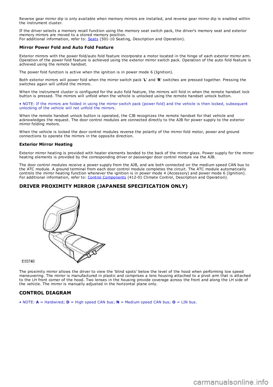
The proximit y mirror al lows t he dri ver t o view the 'blind spot s' below the l evel of t he hood when performing low s peedmaneuvering. The mirror i s manufactured in pl ast ic and compris es a l ens hous ing at tached to a pivot arm t hat i s att achedt o the LH front corner of t he hood. Two l enses i n t he hous i ng provide coverage across the front and along t he LH s i de oft he vehi cl e. The mirror is manual ly adjus t ed in the hori zont al pl ane only.
CONTROL DIAGRAM
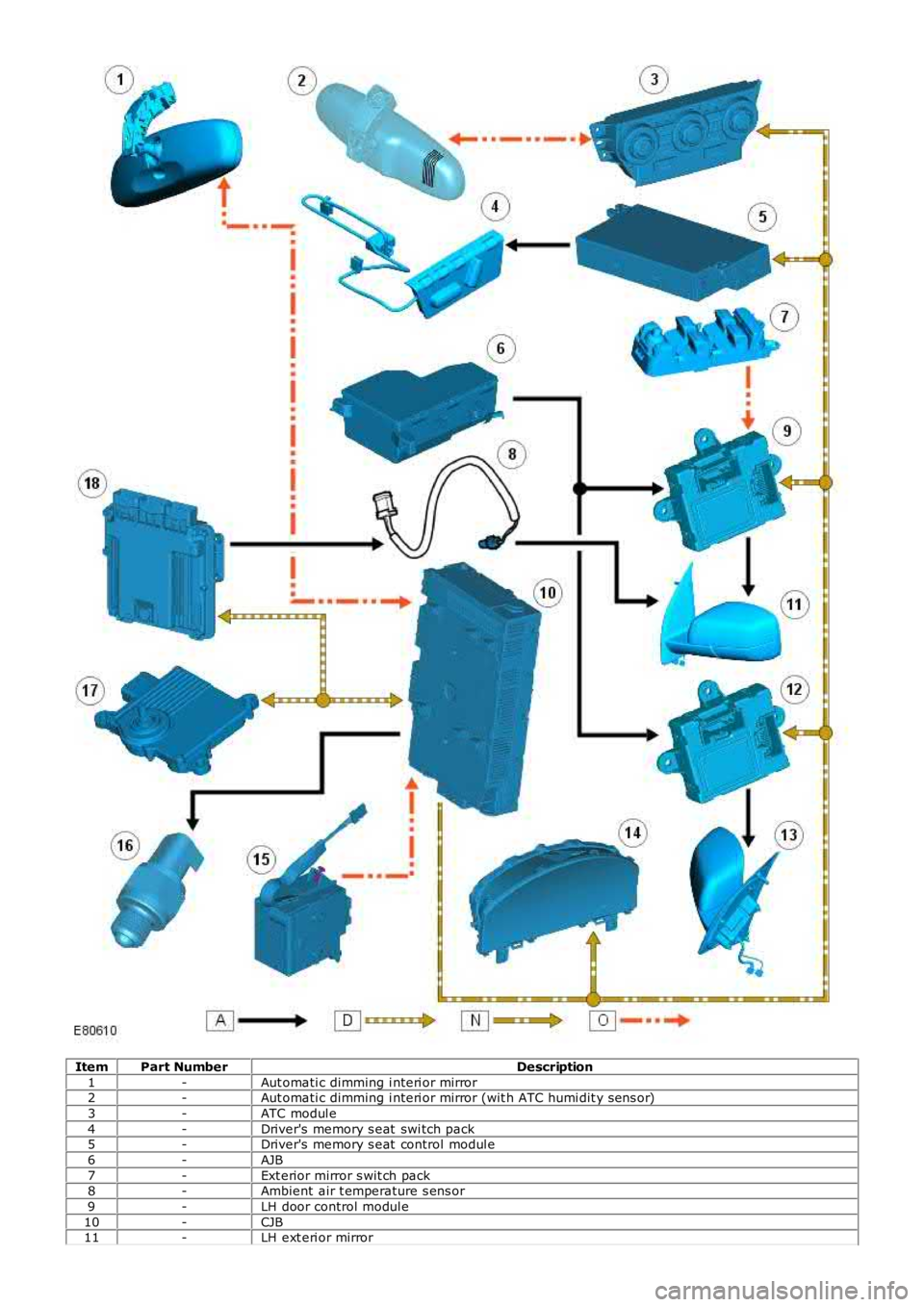
• NOTE: A = Hardwi red; D = Hi gh s peed CAN bus ; N = Medi um s peed CAN bus; O = LIN bus .
Page 2164 of 3229
ItemPart NumberDescription
1-Aut omati c dimming i nteri or mirror2-Aut omati c dimming i nteri or mirror (wit h ATC humi dit y s ens or)
3-ATC modul e
4-Driver's memory s eat swi tch pack5-Driver's memory s eat control modul e
6-AJB
7-Ext erior mirror s wit ch pack8-Ambient air t emperature s ens or
9-LH door control modul e
10-CJB11-LH ext eri or mirror
Page 2165 of 3229

12-RH door control modul e
13-RH exteri or mirror
14-Ins trument cl ust er15-St art control modul e
16-Revers e gear s wit ch - manual t rans mi ss ion
17-TCM - automat ic t rans mis s ion18-ECM
Page 2166 of 3229
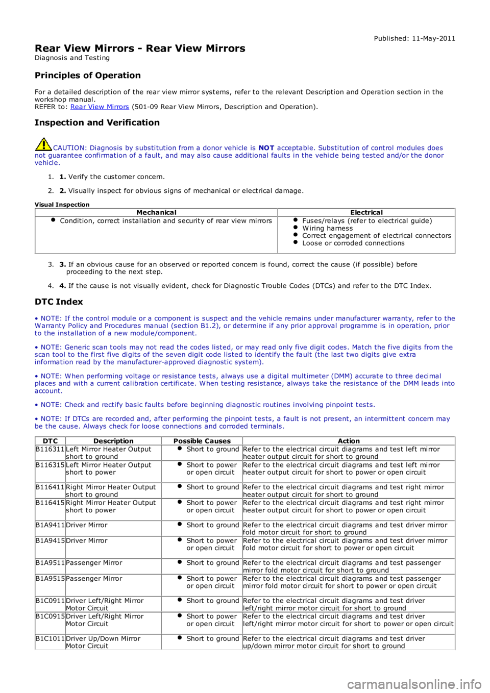
Publi s hed: 11-May-2011
Rear View Mirrors - Rear View Mirrors
Diagnosi s and Tes ti ng
Principles of Operation
For a detail ed descripti on of the rear vi ew mirror s ys t ems, refer t o t he rel evant Descripti on and Operat ion s ecti on in t heworks hop manual .REFER to: Rear View Mirrors (501-09 Rear View Mirrors, Des cri pt ion and Operati on).
Inspection and Verification
CAUTION: Di agnos is by s ubs ti tut ion from a donor vehicle is NO T acceptabl e. Subs ti tut ion of cont rol modules doesnot guarant ee confirmat ion of a faul t, and may als o caus e addit ional fault s i n t he vehi cl e being t est ed and/or t he donorvehi cl e.
1. Verify t he cus t omer concern.1.
2. Vis ually ins pect for obvious s igns of mechani cal or electrical damage.2.
Visual InspectionMechanicalElectrical
Condit ion, correct ins tal lati on and s ecurit y of rear view mirrorsFus es/rel ays (refer to elect rical guide)W iring harnes sCorrect engagement of el ect ri cal connect orsLoos e or corroded connecti ons
3. If an obvious cause for an obs erved or report ed concern is found, correct t he caus e (if pos s ible) beforeproceeding t o t he next s t ep.3.
4. If t he caus e is not vis ually evi dent , check for Di agnos ti c Trouble Codes (DTCs) and refer t o t he DTC Index.4.
DTC Index
• NOTE: If the control modul e or a component i s s us pect and the vehicle remains under manufacturer warrant y, refer t o theW arranty Pol icy and Procedures manual (s ect ion B1.2), or determine i f any pri or approval programme is in operat ion, pri ort o the ins tall ati on of a new module/component.
• NOTE: Generic scan t ool s may not read the codes li st ed, or may read only fi ve digit codes . Mat ch the five di git s from t hes can tool to the firs t fi ve di git s of the seven digi t code l is ted to ident ify t he faul t (t he las t t wo digi ts gi ve ext rainformat ion read by the manufact urer-approved diagnost ic s ys tem).
• NOTE: W hen performing volt age or res is t ance t est s , always use a digi tal mult imeter (DMM) accurat e t o t hree deci malplaces and wit h a current cal ibrat ion cert ificate. W hen tes ti ng res i st ance, always take the res is tance of the DMM l eads i ntoaccount.
• NOTE: Check and recti fy bas ic faul ts before beginni ng diagnos t ic rout ines i nvol vi ng pinpoint t es t s.
• NOTE: If DTCs are recorded and, aft er performi ng the pi npoi nt tes ts , a fault is not present , an int ermi tt ent concern maybe t he caus e. Always check for loose connect ions and corroded terminals .
DT CDescriptionPossible CausesActionB116311Left Mirror Heat er Outputs hort t o groundShort t o groundRefer t o t he electrical ci rcuit diagrams and tes t l eft mi rrorheater output circui t for s hort t o ground
B116315Left Mirror Heat er Outputs hort t o powerShort t o poweror open circuitRefer t o t he electrical ci rcuit diagrams and tes t l eft mi rrorheater output circui t for s hort t o power or open circui t
B116411Ri ght Mi rror Heat er Outputs hort t o groundShort t o groundRefer t o t he electrical ci rcuit diagrams and tes t right mirrorheater output circui t for s hort t o groundB116415Ri ght Mi rror Heat er Outputs hort t o powerShort t o poweror open circuitRefer t o t he electrical ci rcuit diagrams and tes t right mirrorheater output circui t for s hort t o power or open circui t
B1A9411Driver MirrorShort t o groundRefer t o t he electrical ci rcuit diagrams and tes t dri ver mirrorfol d mot or ci rcuit for short to ground
B1A9415Driver MirrorShort t o poweror open circuitRefer t o t he electrical ci rcuit diagrams and tes t dri ver mirrorfol d mot or ci rcuit for short to power or open ci rcuit
B1A9511Pas senger MirrorShort t o groundRefer t o t he electrical ci rcuit diagrams and tes t pas sengermi rror fold motor circui t for s hort t o ground
B1A9515Pas senger MirrorShort t o poweror open circuitRefer t o t he electrical ci rcuit diagrams and tes t pas sengermi rror fold motor circui t for s hort t o power or open circui t
B1C0911Driver Left/Right Mi rrorMot or CircuitShort t o groundRefer t o t he electrical ci rcuit diagrams and tes t dri verl eft/right mirror mot or ci rcuit for short to groundB1C0915Driver Left/Right Mi rrorMot or CircuitShort t o poweror open circuitRefer t o t he electrical ci rcuit diagrams and tes t dri verl eft/right mirror mot or ci rcuit for short to power or open ci rcuit
B1C1011Driver Up/Down MirrorMot or CircuitShort t o groundRefer t o t he electrical ci rcuit diagrams and tes t dri verup/down mirror mot or ci rcuit for s hort t o ground
Page 2167 of 3229
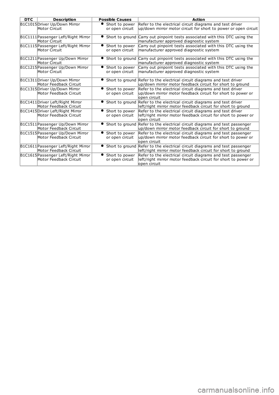
DT CDescriptionPossible CausesAction
B1C1015Driver Up/Down MirrorMot or CircuitShort t o poweror open circuitRefer t o t he electrical ci rcuit diagrams and tes t dri verup/down mirror mot or ci rcuit for s hort t o power or open ci rcuit
B1C1111Pas senger Left/Right Mi rrorMot or CircuitShort t o groundCarry out pinpoint t es t s as sociat ed wit h t his DTC us i ng themanufacturer approved di agnos ti c s ys t em
B1C1115Pas senger Left/Right Mi rrorMot or CircuitShort t o poweror open circuitCarry out pinpoint t es t s as sociat ed wit h t his DTC us i ng themanufacturer approved di agnos ti c s ys t em
B1C1211Pas senger Up/Down MirrorMot or CircuitShort t o groundCarry out pinpoint t es t s as sociat ed wit h t his DTC us i ng themanufacturer approved di agnos ti c s ys t emB1C1215Pas senger Up/Down MirrorMot or CircuitShort t o poweror open circuitCarry out pinpoint t es t s as sociat ed wit h t his DTC us i ng themanufacturer approved di agnos ti c s ys t em
B1C1311Driver Up/Down MirrorMot or Feedback Ci rcuitShort t o groundRefer t o t he electrical ci rcuit diagrams and tes t dri verup/down mirror mot or feedback circui t for s hort t o ground
B1C1315Driver Up/Down MirrorMot or Feedback Ci rcuitShort t o poweror open circuitRefer t o t he electrical ci rcuit diagrams and tes t dri verup/down mirror mot or feedback circui t for s hort t o power oropen circuit
B1C1411Driver Left/Right Mi rrorMot or Feedback Ci rcuitShort t o groundRefer t o t he electrical ci rcuit diagrams and tes t dri verl eft/right mirror mot or feedback circui t for s hort t o ground
B1C1415Driver Left/Right Mi rrorMot or Feedback Ci rcuitShort t o poweror open circuitRefer t o t he electrical ci rcuit diagrams and tes t dri verl eft/right mirror mot or feedback circui t for s hort t o power oropen circuit
B1C1511Pas senger Up/Down MirrorMot or Feedback Ci rcuitShort t o groundRefer t o t he electrical ci rcuit diagrams and tes t pas sengerup/down mirror mot or feedback circui t for s hort t o ground
B1C1515Pas senger Up/Down MirrorMot or Feedback Ci rcuitShort t o poweror open circuitRefer t o t he electrical ci rcuit diagrams and tes t pas sengerup/down mirror mot or feedback circui t for s hort t o power oropen circuitB1C1611Pas senger Left/Right Mi rrorMot or Feedback Ci rcuitShort t o groundRefer t o t he electrical ci rcuit diagrams and tes t pas sengerl eft/right mirror mot or feedback circui t for s hort t o ground
B1C1615Pas senger Left/Right Mi rrorMot or Feedback Ci rcuitShort t o poweror open circuitRefer t o t he electrical ci rcuit diagrams and tes t pas sengerl eft/right mirror mot or feedback circui t for s hort t o power oropen circuit
Page 2168 of 3229
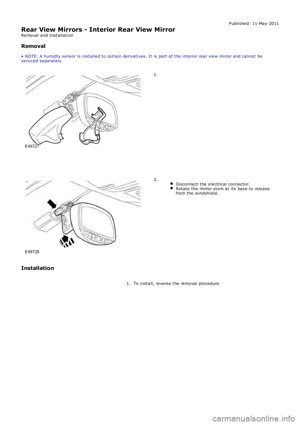
Publi s hed: 11-May-2011
Rear View Mirrors - Interior Rear View Mirror
Removal and Inst all ati on
Removal
• NOTE: A humi dty s ens or i s i ns t alled to cert ain derivati ves . It is part of the i nteri or rear view mirror and cannot bes erviced s eparately.
1.
Di sconnect t he electrical connect or.Rotat e t he mi rror s t em at i ts bas e t o releasefrom the windshi el d.
2.
Installation
To i nst all , revers e t he removal procedure.1.
Page 2169 of 3229
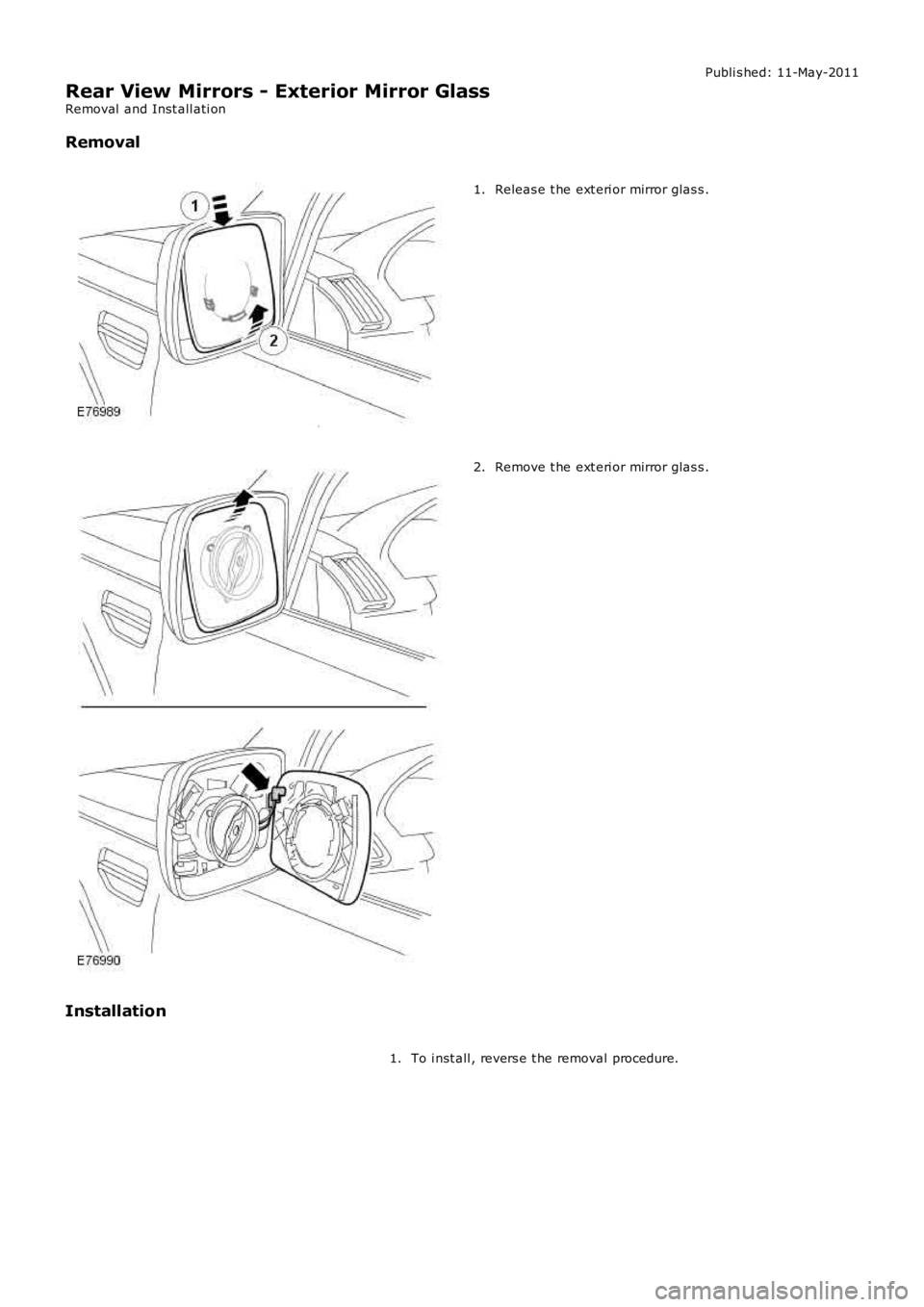
Publi s hed: 11-May-2011
Rear View Mirrors - Exterior Mirror Glass
Removal and Inst all ati on
Removal
Releas e t he ext eri or mirror glas s .1.
Remove t he ext eri or mirror glas s .2.
Installation
To i nst all , revers e t he removal procedure.1.
Page 2170 of 3229
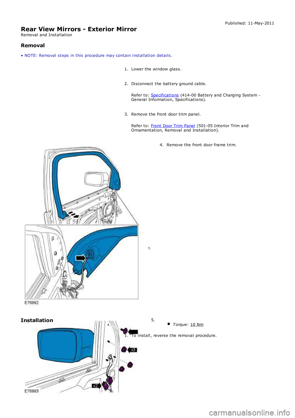
Publi s hed: 11-May-2011
Rear View Mirrors - Exterior Mirror
Removal and Inst all ati on
Removal
• NOTE: Removal s t eps in t his procedure may cont ain i nst all ati on det ail s.
Lower the wi ndow glas s .
1.
Di sconnect t he bat t ery ground cable.
Refer t o: Specificati ons (414-00 Bat tery and Charging Sys tem -
General Informat ion, Specificati ons).
2.
Remove t he front door t ri m panel.
Refer t o: Front Door Trim Panel (501-05 Int eri or Trim and
Ornament ati on, Removal and Ins tal lat ion).
3. Remove the front door frame t ri m.
4.
T orque: 10 Nm 5.
Installation
To i nst all , revers e t he removal procedure.
1.