LAND ROVER FRELANDER 2 2006 Repair Manual
FRELANDER 2 2006
LAND ROVER
LAND ROVER
https://www.carmanualsonline.info/img/64/57251/w960_57251-0.png
LAND ROVER FRELANDER 2 2006 Repair Manual
Trending: oil capacity, oil filter, tailgate, oil change, cruise control, stop start, service interval
Page 2131 of 3229
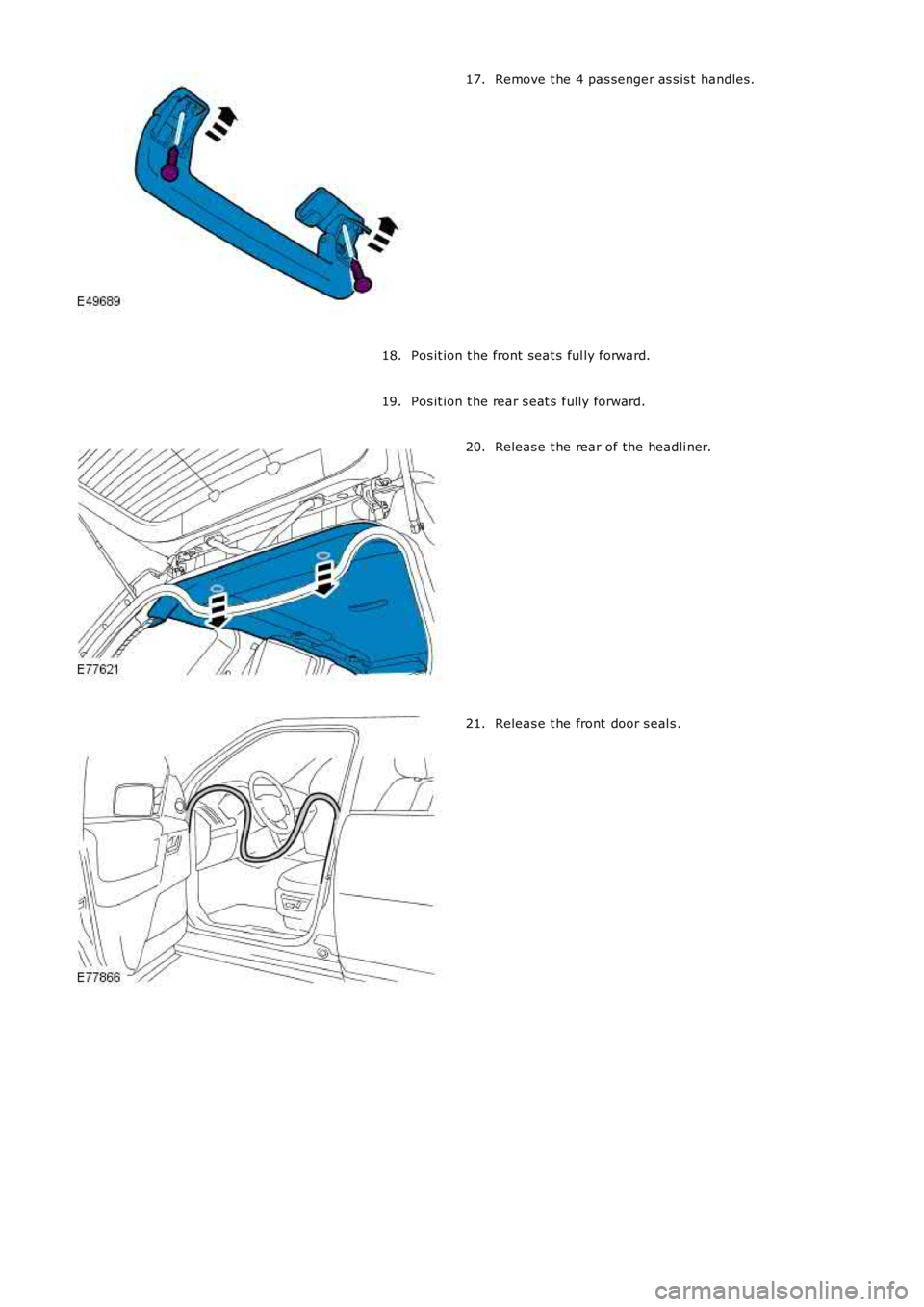
Remove t he 4 pas senger as s is t handles .17.
Pos it ion t he front seat s ful ly forward.18.
Pos it ion t he rear s eat s fully forward.19.
Releas e t he rear of the headli ner.20.
Releas e t he front door s eal s .21.
Page 2132 of 3229
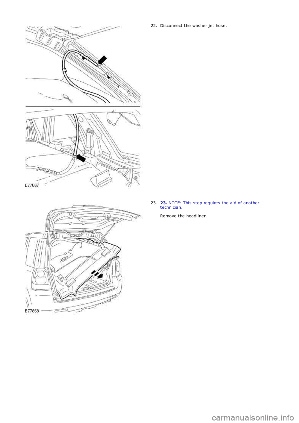
Di sconnect t he washer jet hos e.22.
23. NOTE: Thi s s tep requires the ai d of anot hert echnician.
Remove t he headl iner.
23.
Page 2133 of 3229
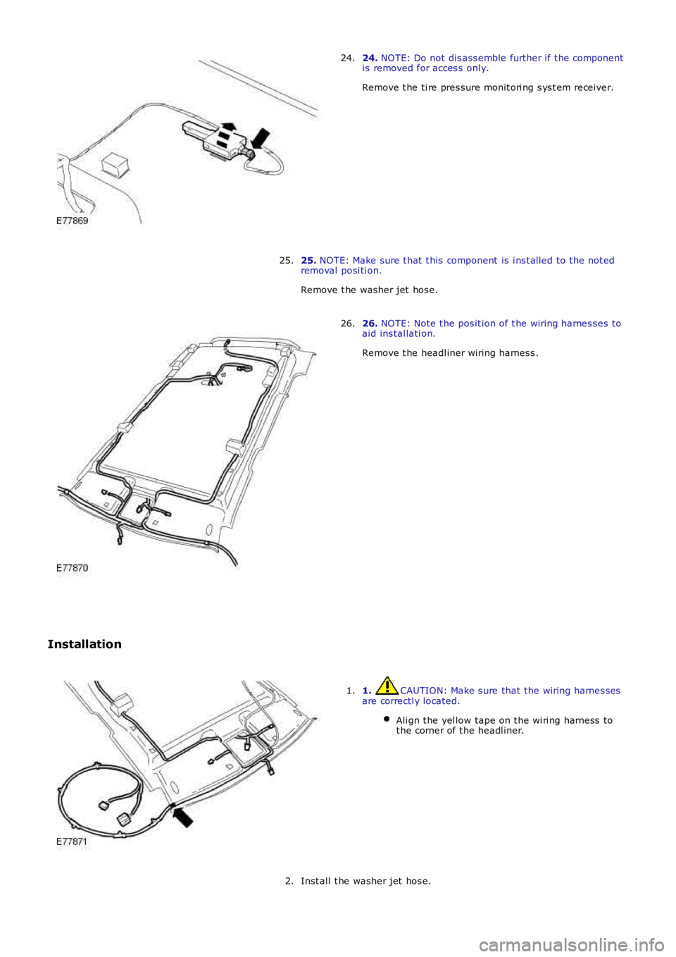
24. NOTE: Do not dis ass emble further if t he componenti s removed for acces s onl y.
Remove t he ti re pres sure monit ori ng s ys t em receiver.
24.
25. NOTE: Make sure t hat t his component is i ns t alled to the not edremoval posi ti on.
Remove t he washer jet hos e.
25.
26. NOTE: Note t he pos it ion of t he wiring harnes s es toaid ins tal lati on.
Remove t he headl iner wiring harnes s .
26.
Installation
1. CAUTION: Make s ure that the wiring harnes s esare correctl y located.
Ali gn t he yel low tape on t he wi ri ng harness tot he corner of t he headl iner.
1.
Inst all t he washer jet hos e.2.
Page 2134 of 3229
Inst all t he ti re pres sure monit ori ng s ys t em receiver.
3.
4. NOTE: Thi s s tep requires the ai d of anot her techni ci an.
Inst all t he headl iner.
4.
Connect t he was her jet hos e.
5.
At tach t he front door s eal s .
6.
At tach t he rear of the headli ner.
7.
Reposi ti on the rear s eat s .
8.
Reposi ti on the front s eats .
9.
Inst all t he pas s enger as s is t handl es .
10.
Inst all t he s un vi s ors .
11.
Inst all t he rear int eri or l amp.
12.
Inst all t he overhead cons ol e.
Refer t o: Overhead Cons ole (501-12 Ins trument Panel and Cons ole,
Removal and Ins tall ati on).
13.
Inst all t he int erior rear vi ew mi rror.
Refer t o: Int erior Rear View Mirror (501-09 Rear Vi ew Mi rrors ,
Removal and Ins tall ati on).
14.
Connect t he headl iner wiring harnes s and s ecure t he cl ips .
15.
Inst all t he s peaker gril le.
16.
Inst all t he cowl s ide trim panel .
Refer t o: Cowl Si de Tri m Panel (501-05 Interior Tri m and
Ornament ati on, Removal and Ins tal lat ion).
17.
Inst all t he glove compartment .
Refer t o: Glove Compart ment (501-12 Ins trument Panel and
Consol e, Removal and Ins t al lat ion).
18.
Inst all t he rear quart er t ri m panel.
19.
Inst all t he loadspace s ecuring ring and t ight en the Torx s crew.
T orque: 25 Nm 20.
Inst all t he D-pi llar t ri m panels .
Refer t o: D-Pi llar Trim Panel (501-05 Int eri or Trim and
Ornament ati on, Removal and Ins tal lat ion).
21.
Page 2135 of 3229
Inst all t he C-pi llar t ri m panels .
Refer t o: C-Pil lar Tri m Panel (501-05 Int erior Trim andOrnament ati on, Removal and Ins tal lat ion).
22.
Inst all t he B-pi llar t ri m panels .
Refer t o: B-Pil lar Upper Trim Panel (501-05 Interior Tri m andOrnament ati on, Removal and Ins tal lat ion).
23.
Inst all t he A-pi llar t ri m panels .
Refer t o: A-Pil lar Tri m Panel (501-05 Int erior Trim andOrnament ati on, Removal and Ins tal lat ion).
24.
Page 2136 of 3229

Publi s hed: 11-May-2011
Interior Trim and Ornamentation - HeadlinerVehicles With: Tilting Roof
Opening Panel
Removal and Inst all ati on
Removal CAUTION: Make s ure that the wiring harnes s es are correct ly locat ed.
• NOTE: If a headl iner is t o be replaced, i t is i mperat ive t hat the was her hos e and wi ri ng harnes s are i nst all ed to their
ori ginal pos it ions . Fai lure to fol low t hese ins truct ions may impede t he s ide air cur t ain modul e performance.
• NOTE: Note the pos it ion of t he wi ri ng harness es t o aid ins tall ati on.
Remove both A-pil lar t ri m panels .
Refer t o: A-Pil lar Tri m Panel (501-05 Int erior Trim and
Ornament ati on, Removal and Ins tal lat ion).
1.
Remove both B-pil lar upper t ri m panels .
Refer t o: B-Pil lar Upper Trim Panel (501-05 Interior Tri m and
Ornament ati on, Removal and Ins tal lat ion).
2.
Remove both C-pil lar t ri m panels .
Refer t o: C-Pil lar Tri m Panel (501-05 Int erior Trim and
Ornament ati on, Removal and Ins tal lat ion).
3.
Remove both D-pil lar upper t rim panels .
Refer t o: D-Pi llar Trim Panel (501-05 Int eri or Trim and
Ornament ati on, Removal and Ins tal lat ion).
4. Remove t he loadspace s ecuring ring.
5. Remove t he rear quart er t ri m panel.
6.
Page 2137 of 3229
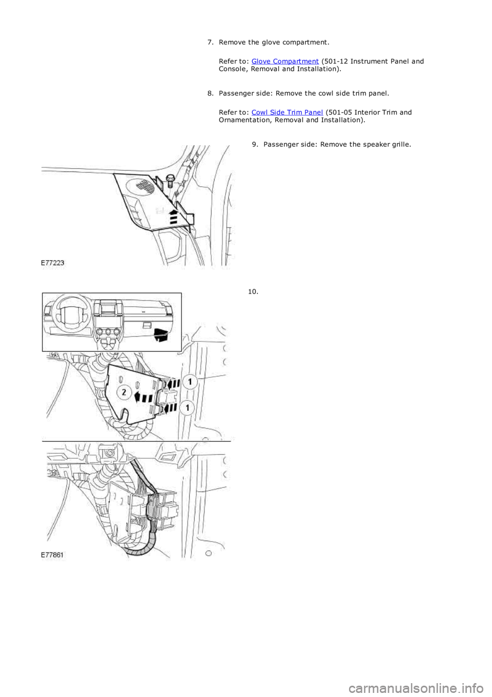
Remove t he glove compartment .
Refer t o: Glove Compart ment (501-12 Ins trument Panel and
Consol e, Removal and Ins t al lat ion).
7.
Pas senger si de: Remove t he cowl si de t ri m panel.
Refer t o: Cowl Si de Tri m Panel (501-05 Interior Tri m and
Ornament ati on, Removal and Ins tal lat ion).
8. Pas senger si de: Remove t he s peaker gri ll e.
9. 10.
Page 2138 of 3229
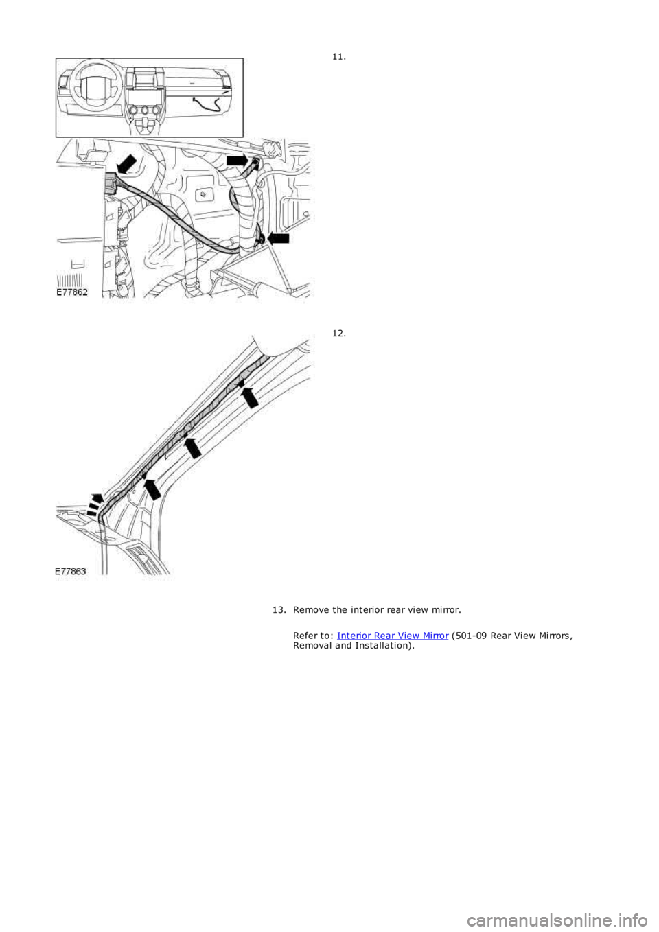
11.
12.
Remove t he int erior rear vi ew mi rror.
Refer t o: Int erior Rear View Mirror (501-09 Rear Vi ew Mi rrors ,
Removal and Ins tall ati on).
13.
Page 2139 of 3229
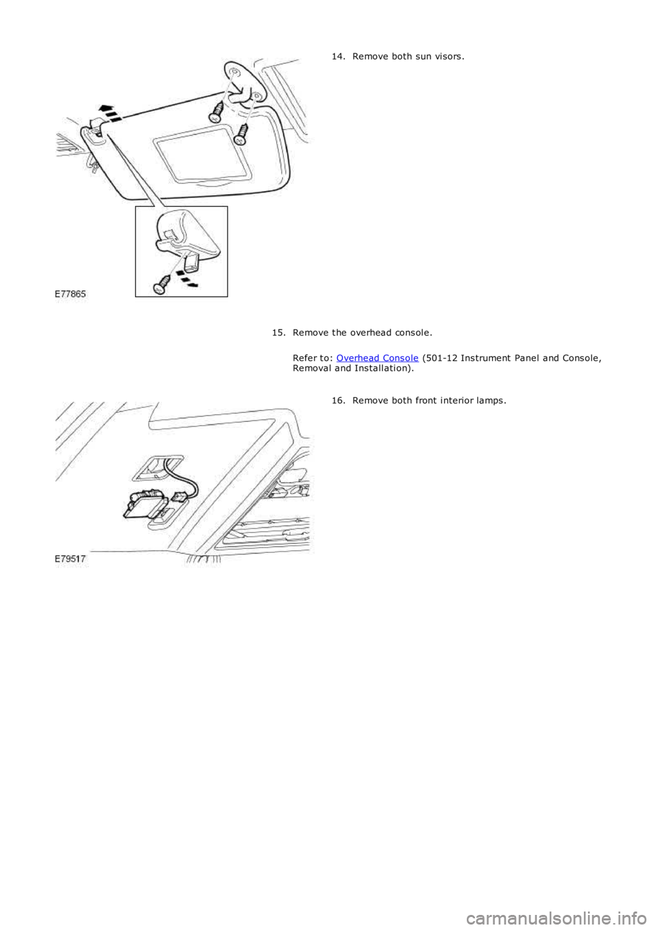
Remove both sun vi sors .
14.
Remove t he overhead cons ol e.
Refer t o: Overhead Cons ole (501-12 Ins trument Panel and Cons ole,
Removal and Ins tall ati on).
15. Remove both front i nterior lamps .
16.
Page 2140 of 3229
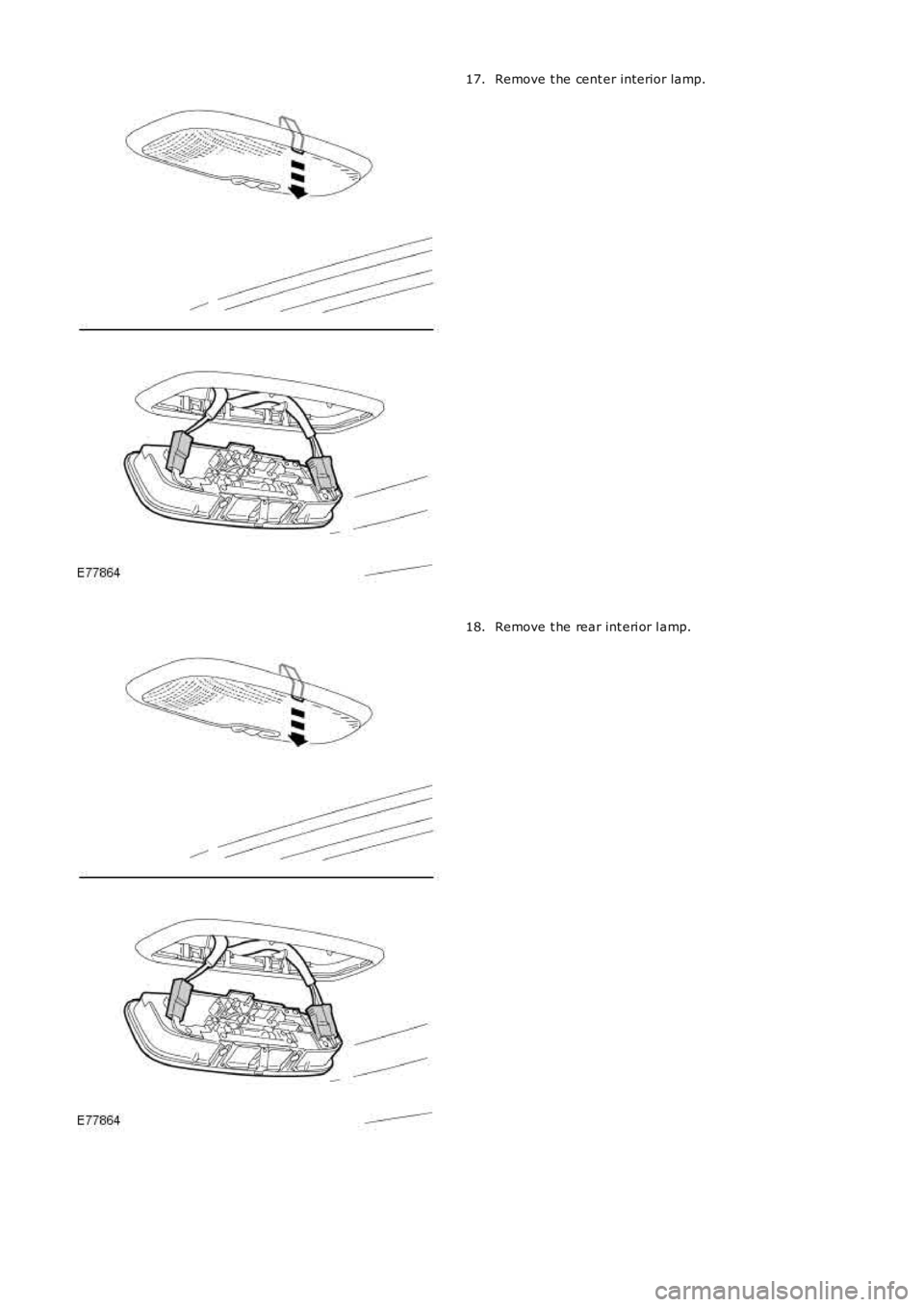
Remove t he cent er interior lamp.
17. Remove t he rear int eri or l amp.
18.
Trending: ESP, park assist, refrigerant type, wheel bolts, radio, isofix, battery location
