LAND ROVER FRELANDER 2 2006 Repair Manual
FRELANDER 2 2006
LAND ROVER
LAND ROVER
https://www.carmanualsonline.info/img/64/57251/w960_57251-0.png
LAND ROVER FRELANDER 2 2006 Repair Manual
Trending: four wheel drive, horn, service, width, oil reset, display, engine overheat
Page 2491 of 3229
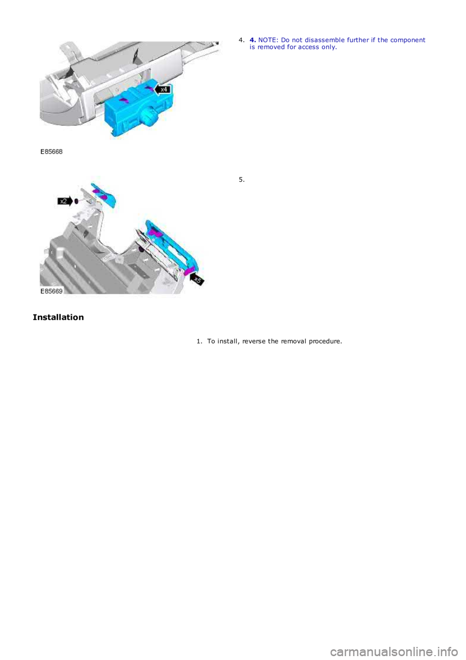
4. NOTE: Do not dis ass embl e further if t he componenti s removed for acces s onl y.4.
5.
Installation
To i nst all , revers e t he removal procedure.1.
Page 2492 of 3229
Publi s hed: 11-May-2011
Supplemental Restraint System - Passenger Air Bag Module
Removal and Inst all ati on
Removal
• NOTE: Removal s t eps in t his procedure may cont ain i nst all ati on det ail s.
Make t he SRS s ys t em s afe.
Refer t o: Standard W orks hop Pract ices (100-00 General Informat ion,Des cript ion and Operat ion).
1.
Remove t he glove compartment .
Refer t o: Glove Compart ment (501-12 Ins trument Panel andConsol e, Removal and Ins t al lat ion).
2.
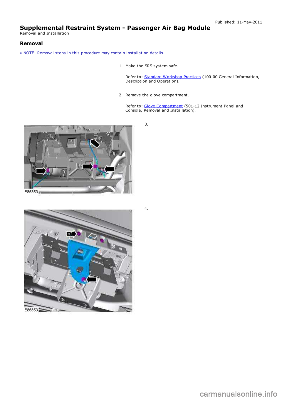
3.
4.
Page 2493 of 3229
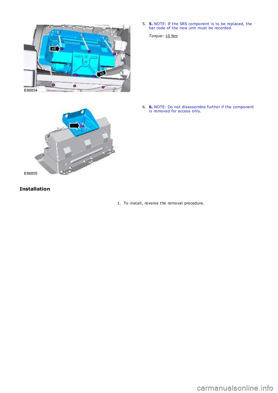
5.
NOTE: If t he SRS component i s to be repl aced, the
bar code of t he new unit must be recorded.
T orque: 10 Nm 5.
6.
NOTE: Do not dis ass embl e further if t he component
i s removed for acces s onl y.
6.
Installation To i nst all , revers e t he removal procedure.
1.
Page 2494 of 3229
Publi s hed: 11-May-2011
Supplemental Restraint System - Side Air Bag Module
Removal and Inst all ati on
Removal
• NOTE: Removal s t eps in t his procedure may cont ain i nst all ati on det ail s.
Make t he SRS s ys t em s afe.
Refer t o: Standard W orks hop Pract ices (100-00 General Informat ion,
Des cript ion and Operat ion).
1.
Remove t he front seat backres t cover.
Refer t o: Front Seat Backres t Cover (501-10 Seat ing, Removal and
Inst all at ion).
2.
Remove t he front seat backres t pad.
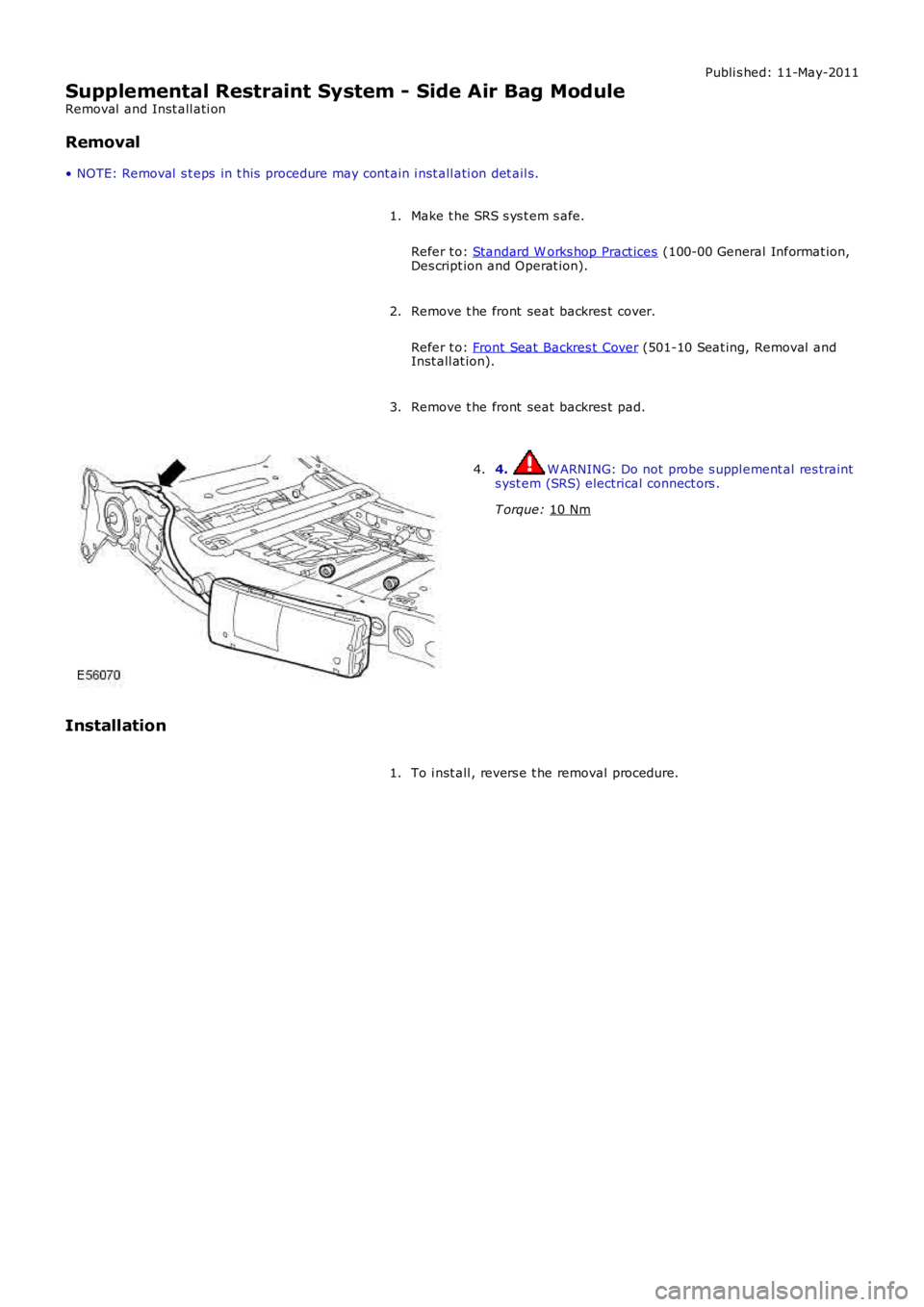
3. 4. W ARNING: Do not probe s uppl ement al res traint
s yst em (SRS) electrical connect ors .
T orque: 10 Nm 4.
Installation To i nst all , revers e t he removal procedure.
1.
Page 2495 of 3229
Publi s hed: 11-May-2011
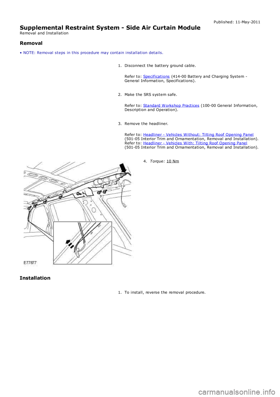
Supplemental Restraint System - Side Air Curtain Module
Removal and Inst all ati on
Removal
• NOTE: Removal s t eps in t his procedure may cont ain i nst all ati on det ail s.
Di sconnect t he bat t ery ground cable.
Refer t o: Specificati ons (414-00 Bat tery and Charging Sys tem -
General Informat ion, Specificati ons).
1.
Make t he SRS s ys t em s afe.
Refer t o: Standard W orks hop Pract ices (100-00 General Informat ion,
Des cript ion and Operat ion).
2.
Remove t he headl iner.
Refer t o: Headl iner - Vehi cl es W i thout: Ti lt ing Roof Opening Panel (501-05 Int eri or Trim and Ornament ati on, Removal and Ins tal lati on).
Refer t o: Headl iner - Vehi cl es W i th: Ti lt ing Roof Openi ng Panel (501-05 Int eri or Trim and Ornament ati on, Removal and Ins tal lati on).
3. T orque:
10 Nm 4.
Installation To i nst all , revers e t he removal procedure.
1.
Page 2496 of 3229
Publi s hed: 11-May-2011
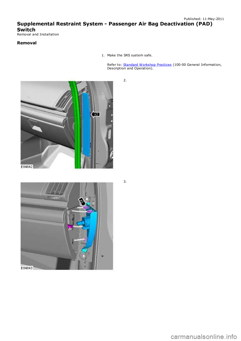
Supplemental Restraint System - Passenger Air Bag Deactivation (PAD)
Switch
Removal and Inst all ati on
Removal
Make t he SRS s ys t em s afe.
Refer t o: Standard W orks hop Pract ices (100-00 General Informat ion,Des cript ion and Operat ion).
1.
2.
3.
Page 2497 of 3229
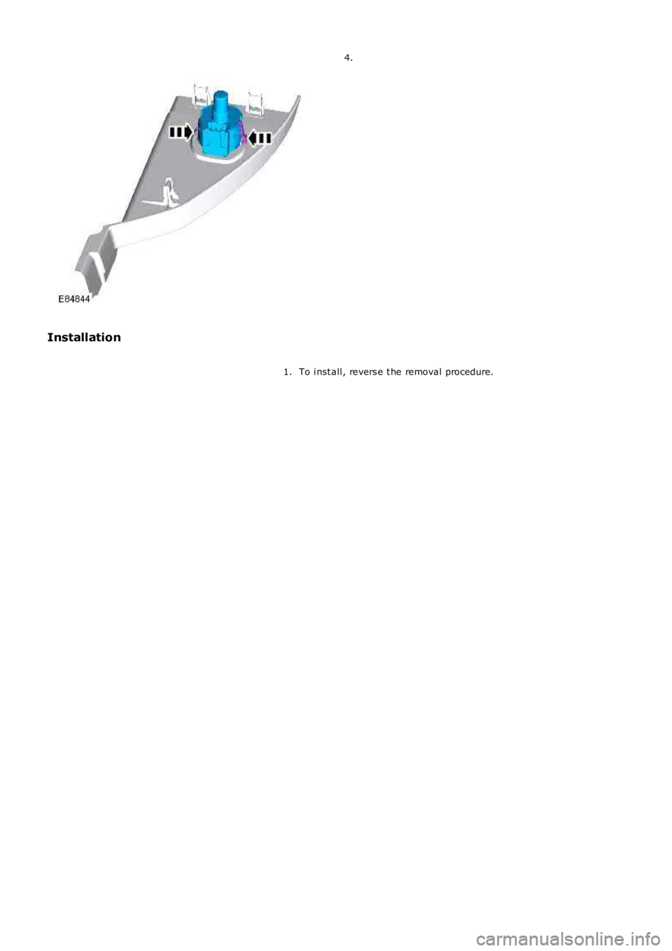
4.
Installation
To i nst all , revers e t he removal procedure.1.
Page 2498 of 3229
Publi s hed: 11-May-2011
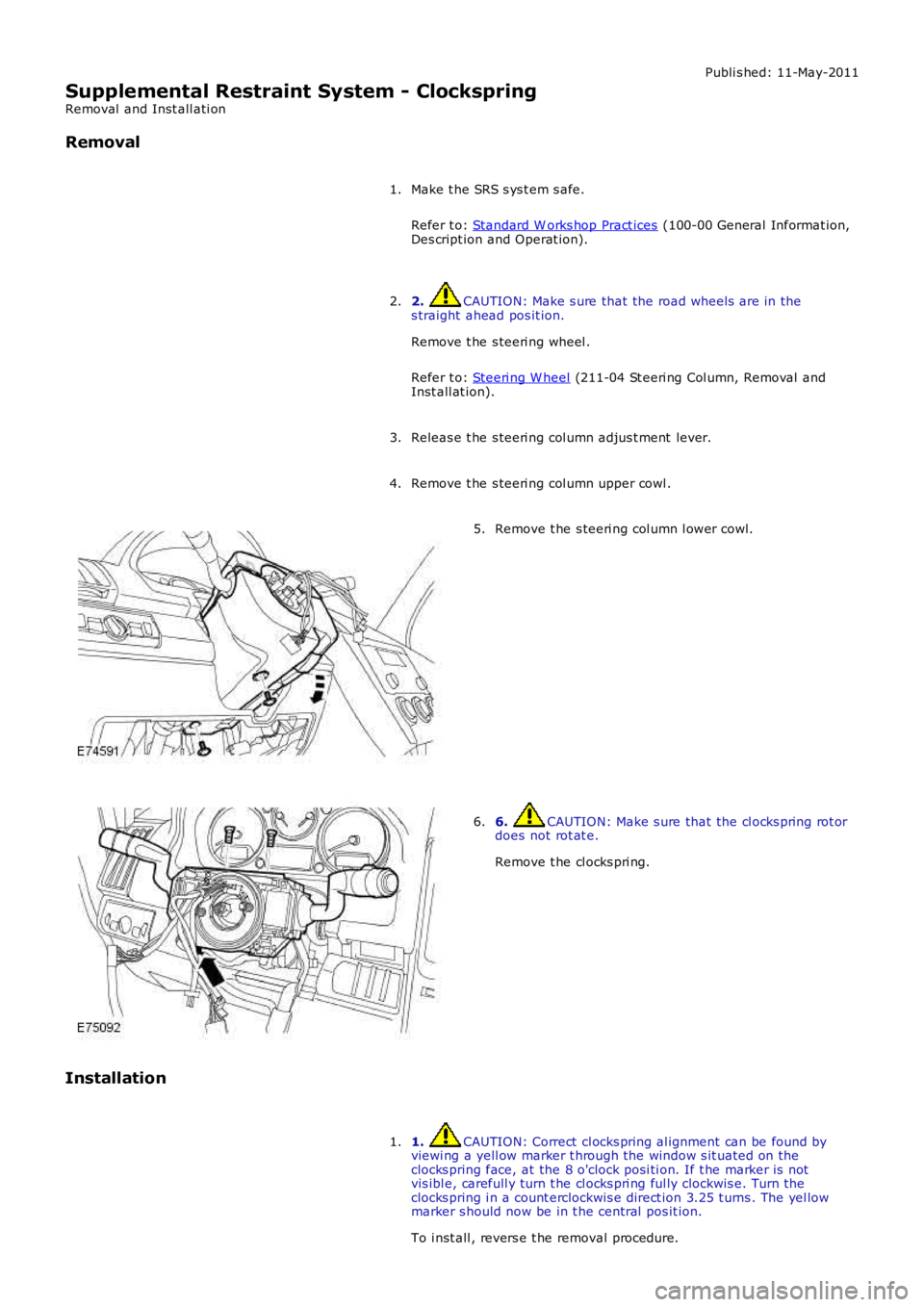
Supplemental Restraint System - Clockspring
Removal and Inst all ati on
Removal
Make t he SRS s ys t em s afe.
Refer t o: Standard W orks hop Pract ices (100-00 General Informat ion,Des cript ion and Operat ion).
1.
2. CAUTION: Make s ure that the road wheels are in thes traight ahead pos it ion.
Remove t he s teeri ng wheel .
Refer t o: Steeri ng W heel (211-04 St eeri ng Col umn, Removal andInst all at ion).
2.
Releas e t he s teeri ng col umn adjus t ment lever.3.
Remove t he s teeri ng col umn upper cowl .4.
Remove t he s teeri ng col umn l ower cowl.5.
6. CAUTION: Make s ure that the cl ocks pring rot ordoes not rot at e.
Remove t he cl ocks pri ng.
6.
Installation
1. CAUTION: Correct cl ocks pring al ignment can be found byviewi ng a yell ow marker t hrough the window s it uated on theclocks pring face, at the 8 o'clock posi ti on. If t he marker is notvis ibl e, carefull y turn t he cl ocks pri ng ful ly clockwis e. Turn t heclocks pring i n a count erclockwis e direct ion 3.25 t urns . The yel lowmarker s hould now be in t he central pos it ion.
To i nst all , revers e t he removal procedure.
1.
Page 2499 of 3229
Publi s hed: 11-May-2011
Supplemental Restraint System - Occupant Classification Sensor
Removal and Inst all ati on
Removal
• NOTE: The occupant cl ass ificati on s ens or is part of the pas s enger s eat cus hion. The sens or is only fi tt ed t o NAS models .
Di sconnect t he bat t ery ground cable.
Refer t o: Specificati ons (414-00 Bat tery and Charging Sys tem -General Informat ion, Specificati ons).
1.
Remove t he front seat cushi on cover.
Refer t o: Front Seat Cus hion Cover (501-10 Seati ng, Removal andInst all at ion).
2.
Installation
Inst all t he front seat cushi on cover.
Refer t o: Front Seat Cus hion Cover (501-10 Seati ng, Removal andInst all at ion).
1.
Connect t he batt ery ground cable.
Refer t o: Specificati ons (414-00 Bat tery and Charging Sys tem -General Informat ion, Specificati ons).
2.
Us ing IDS, configure a new occupant cl ass i fi cat ion s ensor.3.
Page 2500 of 3229
Publi s hed: 11-May-2011
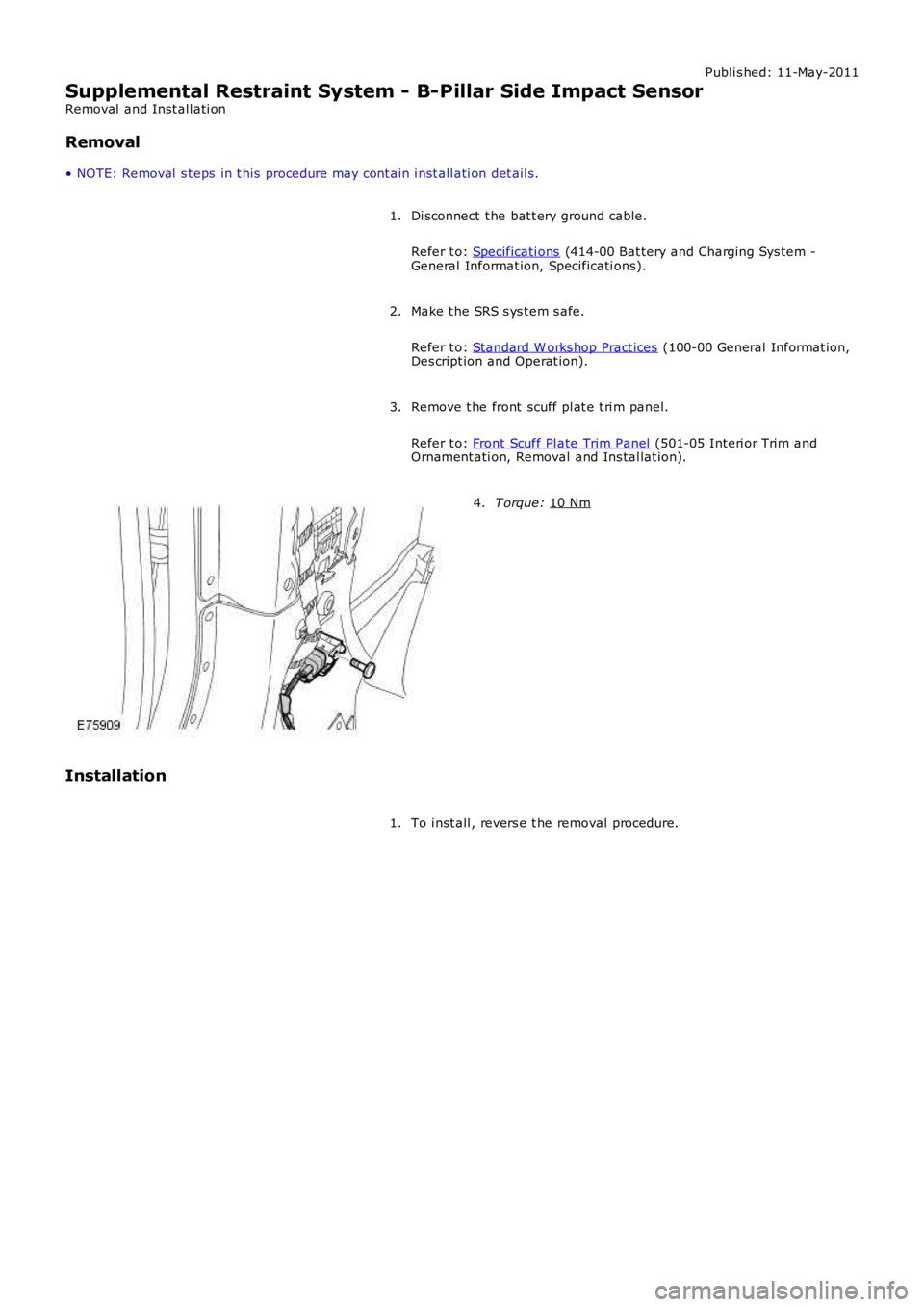
Supplemental Restraint System - B-Pillar Side Impact Sensor
Removal and Inst all ati on
Removal
• NOTE: Removal s t eps in t his procedure may cont ain i nst all ati on det ail s.
Di sconnect t he bat t ery ground cable.
Refer t o: Specificati ons (414-00 Bat tery and Charging Sys tem -
General Informat ion, Specificati ons).
1.
Make t he SRS s ys t em s afe.
Refer t o: Standard W orks hop Pract ices (100-00 General Informat ion,
Des cript ion and Operat ion).
2.
Remove t he front scuff pl at e t ri m panel.
Refer t o: Front Scuff Pl ate Trim Panel (501-05 Interi or Trim and
Ornament ati on, Removal and Ins tal lat ion).
3. T orque:
10 Nm 4.
Installation To i nst all , revers e t he removal procedure.
1.
Trending: mileage, warning light, jacking, fuse diagram, power steering, diagram, fuel tank removal
