LAND ROVER FRELANDER 2 2006 Repair Manual
FRELANDER 2 2006
LAND ROVER
LAND ROVER
https://www.carmanualsonline.info/img/64/57251/w960_57251-0.png
LAND ROVER FRELANDER 2 2006 Repair Manual
Trending: warning light, diagnostic menu, climate control, spare tire, jack points, oil type, weight
Page 2661 of 3229
Publ is hed: 11-May-2011
Rear End Sheet Metal Repairs - Rear Crossmember
Removal and Installation
Removal
• N O T E: T he re a r cro s s me mb e r i s s e rvi ce d a s a s e p a ra t e we l d -o n p a ne l .
• NOTE: The panel is serviced less its weld studs.
1. T he re a r cro s s me mb e r i s re p l a ce d i n co nj unct i o n wi t h:
Rear bumper cover
Re a r bumpe r a rma t ure
Back panel
Inner back panel assembly
Spare wheel well
2. Fo r a d d i t i o na l i nf o rma t i o n re l a t i ng t o t hi s re p a i r p ro ce d ure
please see the following:
Fo r a d d i t i o na l i nf o rma t i o n, re f e r t o : Body and Frame
(501-26
Body Repairs - Vehicle Specific Information and Tolerance
Checks, Description and Operation) /
St a nd a rd W o rks ho p P ra ct i ce s
(100-00 Ge ne ra l I nf o rma t i o n,
Description and Operation).
3. Remove the spare wheel well.
Fo r a d d i t i o na l i nf o rma t i o n, re f e r t o : Spare Wheel W ell
(501-30
Rear End Sheet Metal Repairs, Removal and Installation).
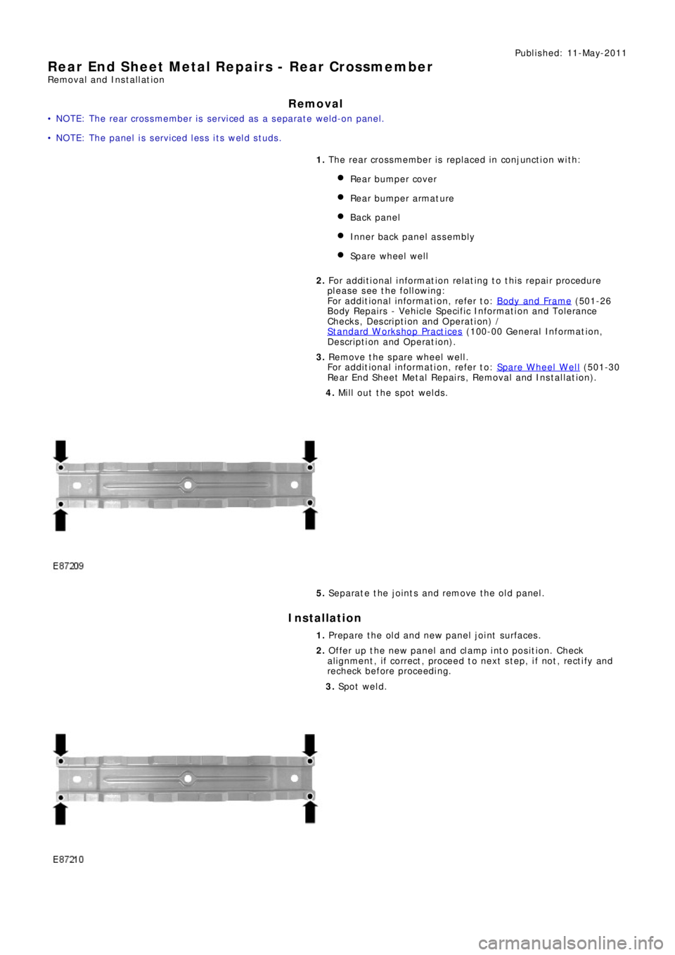
4. Mill out the spot welds.
5. Separate the joints and remove the old panel.
Installation
1. Prepare the old and new panel joint surfaces.
2. Offer up the new panel and clamp into position. Check
al ignment , i f correct , proceed t o next s t ep, i f not , rect i fy and
recheck before proceeding.
3. Sp o t w e l d .
Page 2662 of 3229
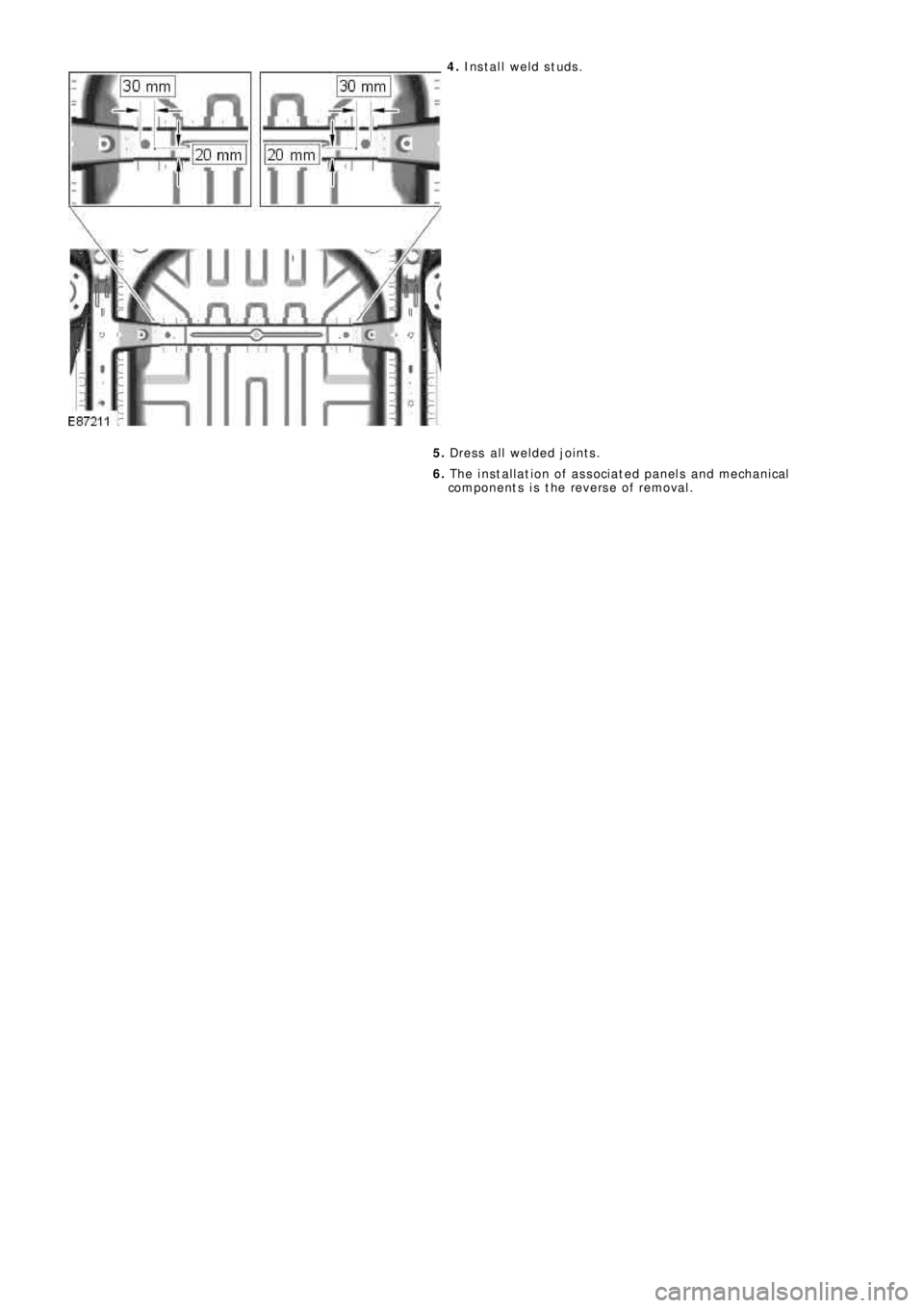
4. Install weld studs.
5. Dress all welded joints.
6. The installation of associated panels and mechanical
components is the reverse of removal.
Page 2663 of 3229
Publ is hed: 11-May-2011
Rear End Sheet Metal Repairs - Rear Side Member Lower Side Extension
Removal and Installation
Removal
• NOTE: The rear side member lower side extension is serviced as a separate weld-on panel, it is also serviced as part of
t he re a r s i de me mbe r.
1. The rear side member lower side extension is replaced in
conjunct ion wit h:
Rear bumper cover
Re a r bumpe r a rma t ure
Rear l amp mount ing panel
2. Fo r a d d i t i o na l i nf o rma t i o n re l a t i ng t o t hi s re p a i r p ro ce d ure
please see the following:
Fo r a d d i t i o na l i nf o rma t i o n, re f e r t o : Body and Frame
(501-26
Body Repairs - Vehicle Specific Information and Tolerance
Checks, Description and Operation) /
St a nd a rd W o rks ho p P ra ct i ce s
(100-00 Ge ne ra l I nf o rma t i o n,
Description and Operation).
3. Re move t he re a r l a mp mount i ng pa ne l .
Fo r a d d i t i o na l i nf o rma t i o n, re f e r t o : Rear Lamp Mount i ng Panel
(501-30 Rear End Sheet Metal Repairs, Removal and
Installation).
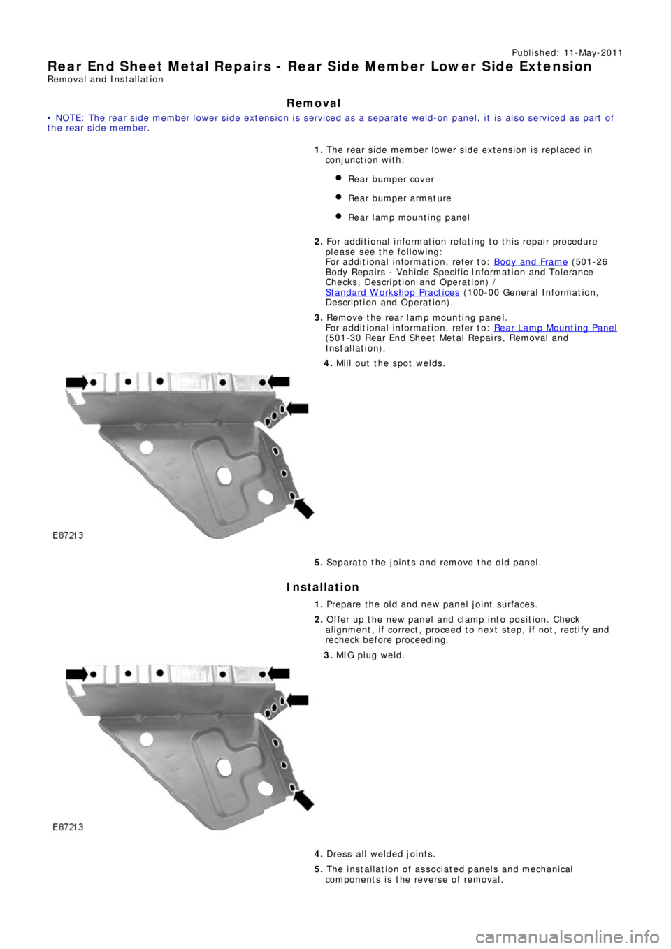
4. Mill out the spot welds.
5. Separate the joints and remove the old panel.
Installation
1. Prepare the old and new panel joint surfaces.
2. Offer up the new panel and clamp into position. Check
al ignment , i f correct , proceed t o next s t ep, i f not , rect i fy and
recheck before proceeding.
3. MIG pl ug we l d.
4. Dress all welded joints.
5. The installation of associated panels and mechanical
components is the reverse of removal.
Page 2664 of 3229
Publ is hed: 11-May-2011
Rear End Sheet Metal Repairs - Rear Lamp Mounting Panel
Removal and Installation
Removal
• NOTE: The rear lamp mounting panel is serviced as a separate weld-on panel.
• NOTE: There are NVH elements attached to the old panel, they are not serviced on the new panel. If damaged, new
elements will be required.
1. The rear lamp mounting panel is replaced in conjunction with:
Rear bumper cover
Re a r bumpe r a rma t ure
2. Fo r a d d i t i o na l i nf o rma t i o n re l a t i ng t o t hi s re p a i r p ro ce d ure
please see the following:
Fo r a d d i t i o na l i nf o rma t i o n, re f e r t o : Body and Frame
(501-26
Body Repairs - Vehicle Specific Information and Tolerance
Checks, Description and Operation) /
St a nd a rd W o rks ho p P ra ct i ce s
(100-00 Ge ne ra l I nf o rma t i o n,
Description and Operation).
3. Re move t he re a r bumpe r.
Fo r a d d i t i o na l i nf o rma t i o n, re f e r t o : Rear Bumper
(501-19
Bumpe rs , Re mo va l a nd Ins t a l l a t i on).
4. Disconnect both battery cables.
5. Remove the D-Pillar trim panel.
Fo r a d d i t i o na l i nf o rma t i o n, re f e r t o : D-Pillar Trim Panel
(501-05
Int erior Trim and Ornamentat ion, Removal and Installat ion).
6. Re mo ve t he re a r w he e l a nd t i re .
7. Remove t he rear quart er window moulding.
8. Remove the loadspace trim panel.
9. Remove the forced air extraction grille.
10. Release the insulating material and lay aside.
11. Release and lay aside the wiring harness.
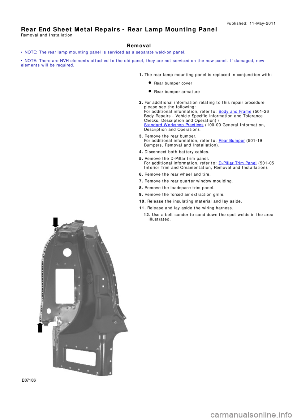
12. Use a belt sander to sand down the spot welds in the area
illustrated.
Page 2665 of 3229
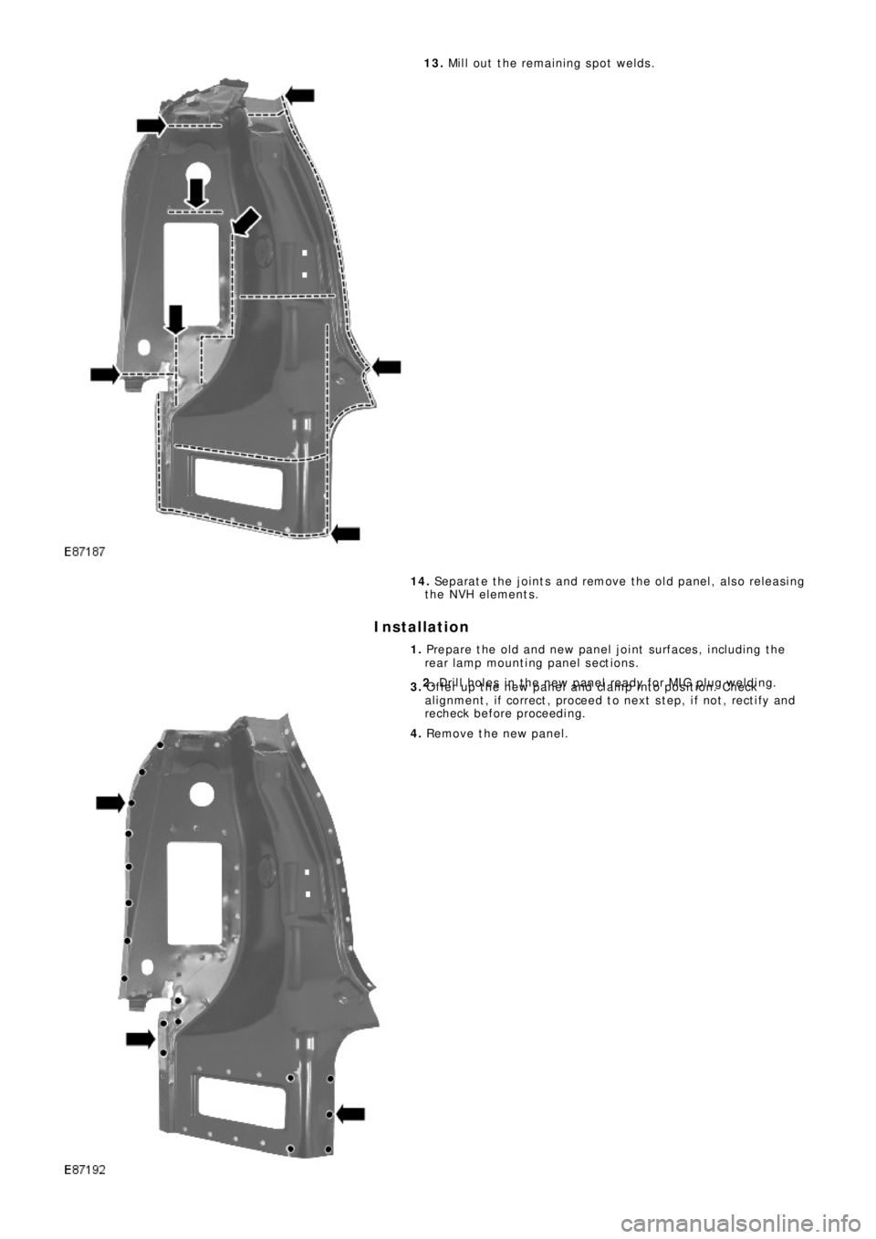
13. Mill out the remaining spot welds.
14. Se p a ra t e t he j o i nt s a nd re mo ve t he o l d p a ne l , a l s o re l e a s i ng
the NVH elements.
Installation
1. Prepare the old and new panel joint surfaces, including the
rear l amp mount i ng panel s ect ions .
2. Drill holes in the new panel ready for MIG plug welding.
3. Offer up the new panel and clamp into position. Check
al ignment , i f correct , proceed t o next s t ep, i f not , rect i fy and
recheck before proceeding.
4. Remove the new panel.
Page 2666 of 3229
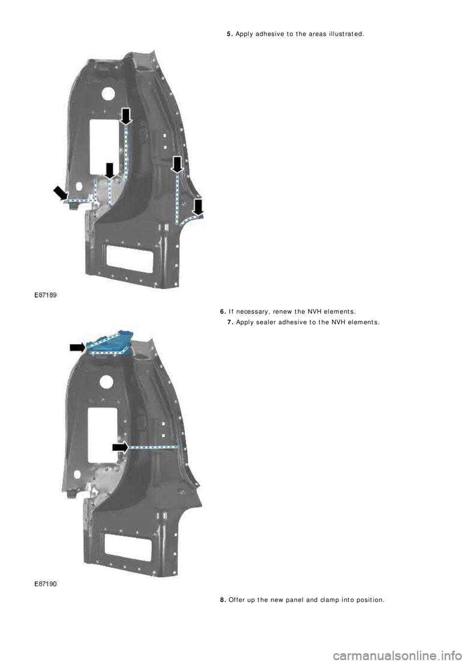
5. Apply adhesive to the areas illustrated.
6. If necessary, renew the NVH elements.
7. Apply sealer adhesive to the NVH elements.
8. Offer up the new panel and clamp into position.
Page 2667 of 3229
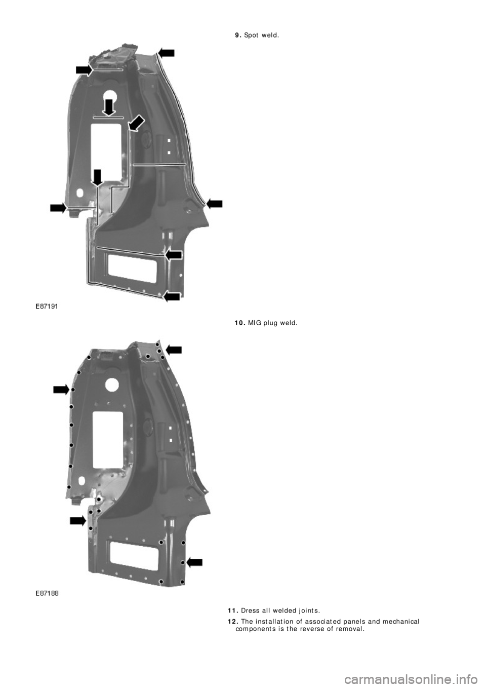
9. Sp o t we l d .
10. MIG pl ug we l d.
11. Dress all welded joints.
12. The installation of associated panels and mechanical
components is the reverse of removal.
Page 2668 of 3229
Publ is hed: 11-May-2011
Rear End Sheet Metal Repairs - Water Drain Panel Section
Removal and Installation
Removal
• NOTE: The wat er drai n panel s ect ion i s cut from t he wat er drai n panel, whi ch is a s eparat e wel d-on panel.
1. The water drain panel s ection is replaced in conjunction with:
Rear bumper cover
Re a r bumpe r a rma t ure
Liftgate
Quarter panel
Rear l amp mount ing panel
2. Fo r a d d i t i o na l i nf o rma t i o n re l a t i ng t o t hi s re p a i r p ro ce d ure
please see the following:
Fo r a d d i t i o na l i nf o rma t i o n, re f e r t o : Body and Frame
(501-26
Body Repairs - Vehicle Specific Information and Tolerance
Checks, Description and Operation) /
St a nd a rd W o rks ho p P ra ct i ce s
(100-00 Ge ne ra l I nf o rma t i o n,
Description and Operation).
3. Remove the quarter panel.
Fo r a d d i t i o na l i nf o rma t i o n, re f e r t o : Quarter Panel
(501-30
Rear End Sheet Metal Repairs, Removal and Installation).
4. Re move t he re a r l a mp mount i ng pa ne l .
Fo r a d d i t i o na l i nf o rma t i o n, re f e r t o : Rear Lamp Mount i ng Panel
(501-30 Rear End Sheet Metal Repairs, Removal and
Installation).
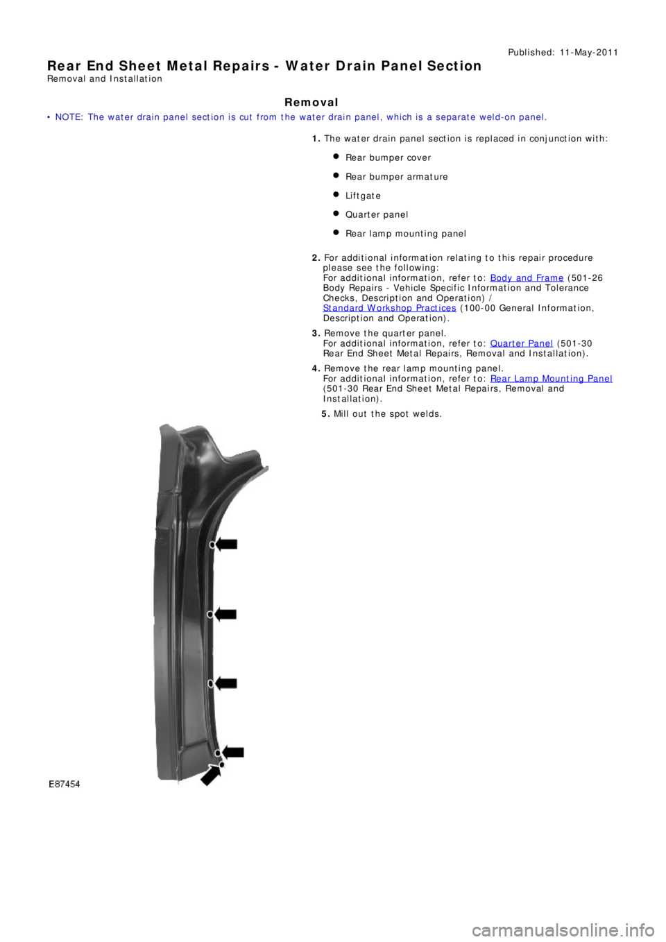
5. Mill out the spot welds.
Page 2669 of 3229
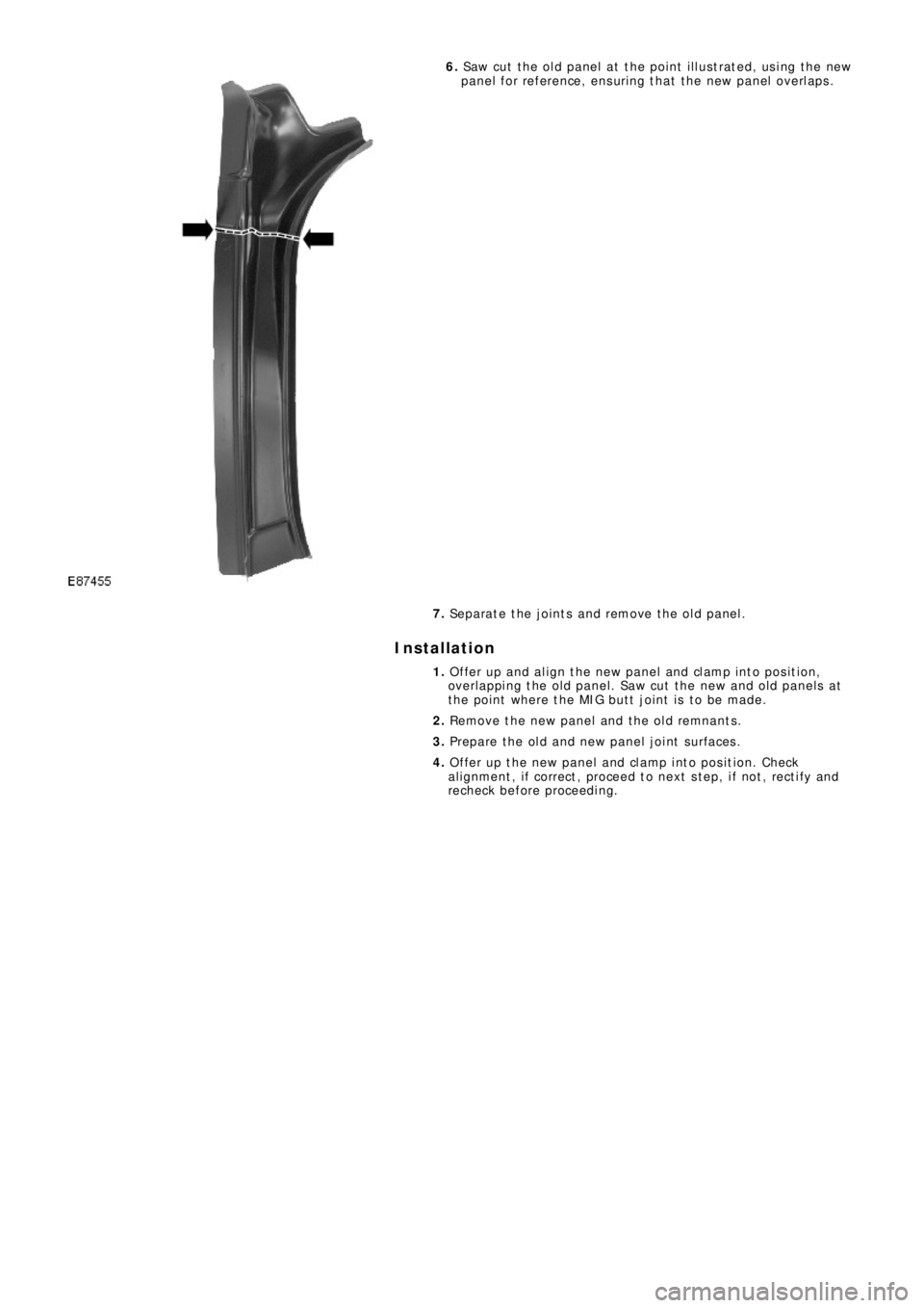
6. Saw cut the old panel at the point illustrated, using the new
p a ne l f o r re f e re nce , e ns uri ng t ha t t he ne w p a ne l o ve rl a p s .
7. Separate the joints and remove the old panel.
Installation
1. Offer up and align the new panel and clamp into position,
overlapping the old panel. Saw cut the new and old panels at
the point where the MIG butt joint is to be made.
2. Remove the new panel and the old remnants.
3. Prepare the old and new panel joint surfaces.
4. Offer up the new panel and clamp into position. Check
al ignment , i f correct , proceed t o next s t ep, i f not , rect i fy and
recheck before proceeding.
Page 2670 of 3229
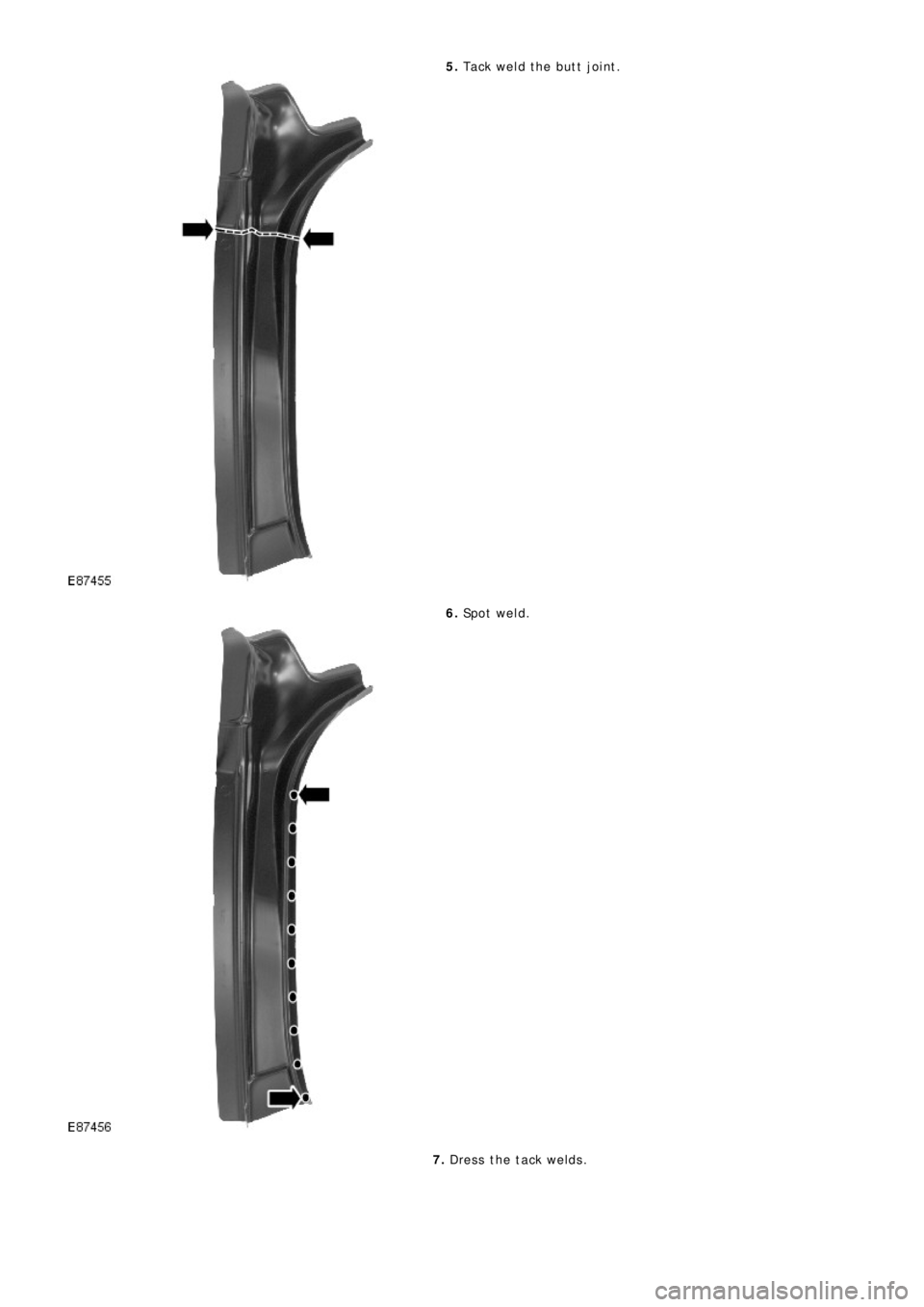
5. Tack weld the butt joint.
6. Sp o t w e l d .
7. Dress the tack welds.
Trending: oil level, brakes, heater, child seat, trip computer, pairing phone, steering wheel adjustment

