LAND ROVER FRELANDER 2 2006 Repair Manual
FRELANDER 2 2006
LAND ROVER
LAND ROVER
https://www.carmanualsonline.info/img/64/57251/w960_57251-0.png
LAND ROVER FRELANDER 2 2006 Repair Manual
Trending: length, relay, AUX, fuel additives, wheel bolt torque, deactivate airbag, change language
Page 2651 of 3229
7. The installation of associated panels and mechanical
components is the reverse of removal.
Page 2652 of 3229
Publ is hed: 11-May-2011
Rear End Sheet Metal Repairs - Rear Wheelhouse Outer
Removal and Installation
Removal
• NOTE: The rear wheelhouse outer is serviced as a separate weld-on panel.
1. The rear wheelhouse outer is replaced in conjunction with:
Rear bumper cover
Quarter panel
Rear door
Quarter glass
I nne r q ua rt e r p a ne l
2. Fo r a d d i t i o na l i nf o rma t i o n re l a t i ng t o t hi s re p a i r p ro ce d ure
please see the following:
Fo r a d d i t i o na l i nf o rma t i o n, re f e r t o : Body and Frame
(501-26
Body Repairs - Vehicle Specific Information and Tolerance
Checks, Description and Operation) /
St a nd a rd W o rks ho p P ra ct i ce s
(100-00 Ge ne ra l I nf o rma t i o n,
Description and Operation).
3. Re mo ve t he i nne r q ua rt e r p a ne l .
Fo r a d d i t i o na l i nf o rma t i o n, re f e r t o : Inner Quart er Panel
(501-30 Rear End Sheet Metal Repairs, Removal and
Installation).
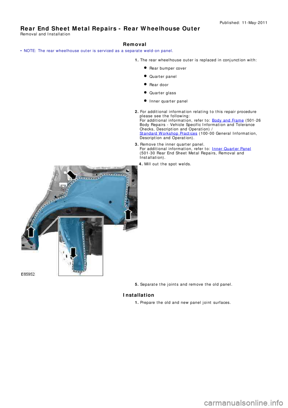
4. Mill out the spot welds.
5. Separate the joints and remove the old panel.
Installation
1. Prepare the old and new panel joint surfaces.
Page 2653 of 3229
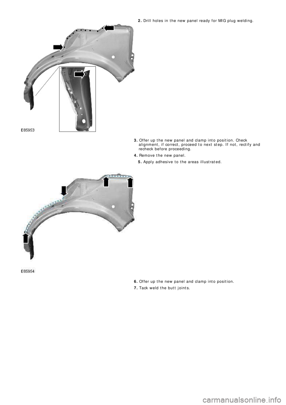
2. Drill holes in the new panel ready for MIG plug welding.
3. Offer up the new panel and clamp into position. Check
alignment, if correct, proceed to next step. If not, rectify and
recheck before proceeding.
4. Remove the new panel.
5. Apply adhesive to the areas illustrated.
6. Offer up the new panel and clamp into position.
7. Tack weld the butt joints.
Page 2654 of 3229
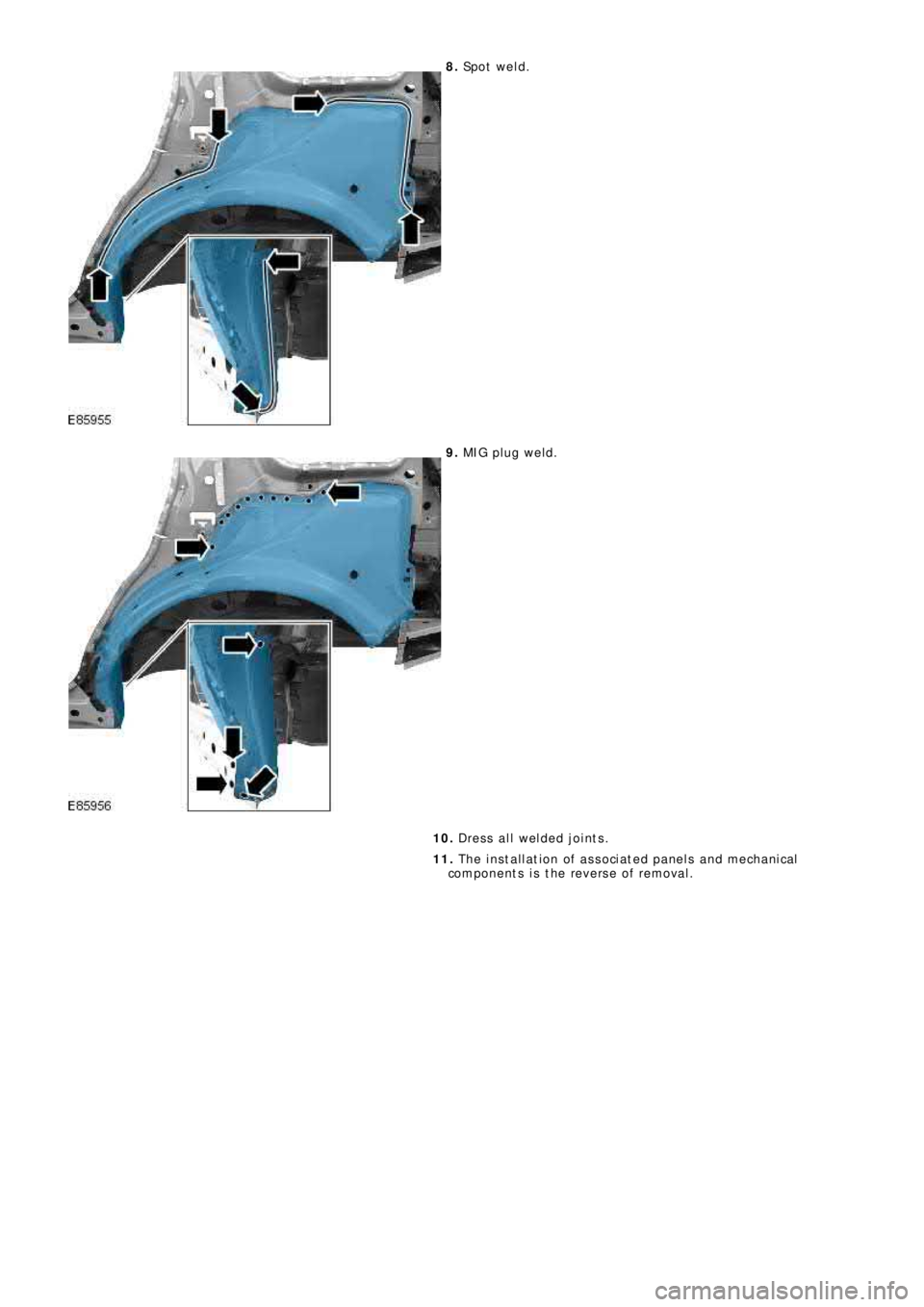
8. Sp o t w e l d .
9. MIG pl ug we l d.
10. Dress all welded joints.
11. The installation of associated panels and mechanical
components is the reverse of removal.
Page 2655 of 3229
Publ is hed: 11-May-2011
Rear End Sheet Metal Repairs - Rear Bumper Mounting
Removal and Installation
Removal
• NOTE: The rear bumper mount ing i s s ervi ced as a s eparat e wel d-on panel.
1. The rear bumper mounting is replaced in conjunction with:
Rear bumper cover
Re a r bumpe r a rma t ure
Back panel
2. Fo r a d d i t i o na l i nf o rma t i o n re l a t i ng t o t hi s re p a i r p ro ce d ure
please see the following:
Fo r a d d i t i o na l i nf o rma t i o n, re f e r t o : Body and Frame
(501-26
Body Repairs - Vehicle Specific Information and Tolerance
Checks, Description and Operation) /
St a nd a rd W o rks ho p P ra ct i ce s
(100-00 Ge ne ra l I nf o rma t i o n,
Description and Operation).
3. Remove the back panel.
Fo r a d d i t i o na l i nf o rma t i o n, re f e r t o : Back Panel
(501-30 Rear
End Sheet Metal Repairs, Removal and Installation).
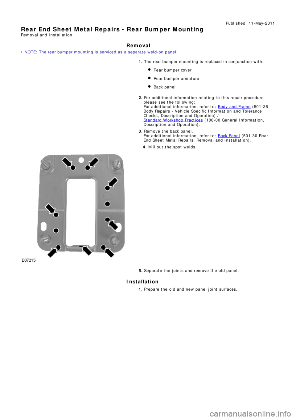
4. Mill out the spot welds.
5. Separate the joints and remove the old panel.
Installation
1. Prepare the old and new panel joint surfaces.
Page 2656 of 3229
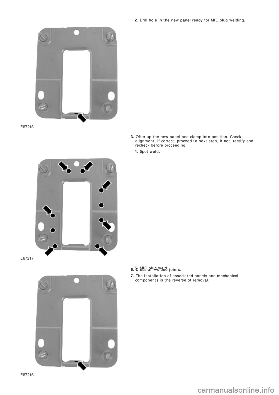
2. Drill hole in the new panel ready for MIG plug welding.
3. Offer up the new panel and clamp into position. Check
al ignment , i f correct , proceed t o next s t ep, i f not , rect i fy and
recheck before proceeding.
4. Sp o t w e l d .
5. MIG pl ug we l d.
6. Dress all welded joints.
7. The installation of associated panels and mechanical
components is the reverse of removal.
Page 2657 of 3229
Publ is hed: 11-May-2011
Rear End Sheet Metal Repairs - Back Panel
Removal and Installation
Removal
• NOTE: The back panel is serviced as a separate weld-on panel, it includes the bumper retaining bracket.
• NOTE: It is necessary to remove sections of both rear lamp mounting panels to enable removal and refitment of the back
panel , (unl es s t he back panel i s being replaced i n conjunct i on wit h a rear l amp mount ing panel ).
1. The back panel is replaced in conjunction with:
Rear bumper cover
Rear bumper
2. Fo r a d d i t i o na l i nf o rma t i o n re l a t i ng t o t hi s re p a i r p ro ce d ure
please see the following:
Fo r a d d i t i o na l i nf o rma t i o n, re f e r t o : Body and Frame
(501-26
Body Repairs - Vehicle Specific Information and Tolerance
Checks, Description and Operation) /
St a nd a rd W o rks ho p P ra ct i ce s
(100-00 Ge ne ra l I nf o rma t i o n,
Description and Operation).
3. Re move t he re a r bumpe r.
Fo r a d d i t i o na l i nf o rma t i o n, re f e r t o : Rear Bumper
(501-19
Bumpe rs , Re mo va l a nd Ins t a l l a t i on).
4. Remove the RH and LH bumper retainer guides.
5. Remove the liftgate aperture weatherseal.
6. Remove the back panel trim.
7. Remove t he RH and LH quart er panel i nner t ri ms .
Fo r a d d i t i o na l i nf o rma t i o n, re f e r t o : Rear Quarter Trim Panel
(501-05 Int eri or Trim and Ornament at i on, Removal and
Installation).
8. Remove the RH and LH forced air extraction grilles.
9. Remove the spare road wheel.
10. Remove the subwoofer amplifier.
Fo r a d d i t i o na l i nf o rma t i o n, re f e r t o : Subwoofer Amplifier
(415-01 Information and Entertainment System, Removal and
Installation).
11. Re move t he e xha us t a s s e mbl y.
Fo r a d d i t i o na l i nf o rma t i o n, re f e r t o : Exhaust Syst em
(309-00A
Exhaus t Sys t em - I6 3.2L Pet rol , Removal and Ins t all at ion).
12. Remove the floor panel exhaust heat shield.
13. Remove the RH and LH road wheels.
Fo r a d d i t i o na l i nf o rma t i o n, re f e r t o : Wheel and Tire
(204-04
Wheels and Tires, Removal and Installation).
14. Release and lay aside the insulating material at the back
panel.
15. Release and lay aside the back panel wiring harness.
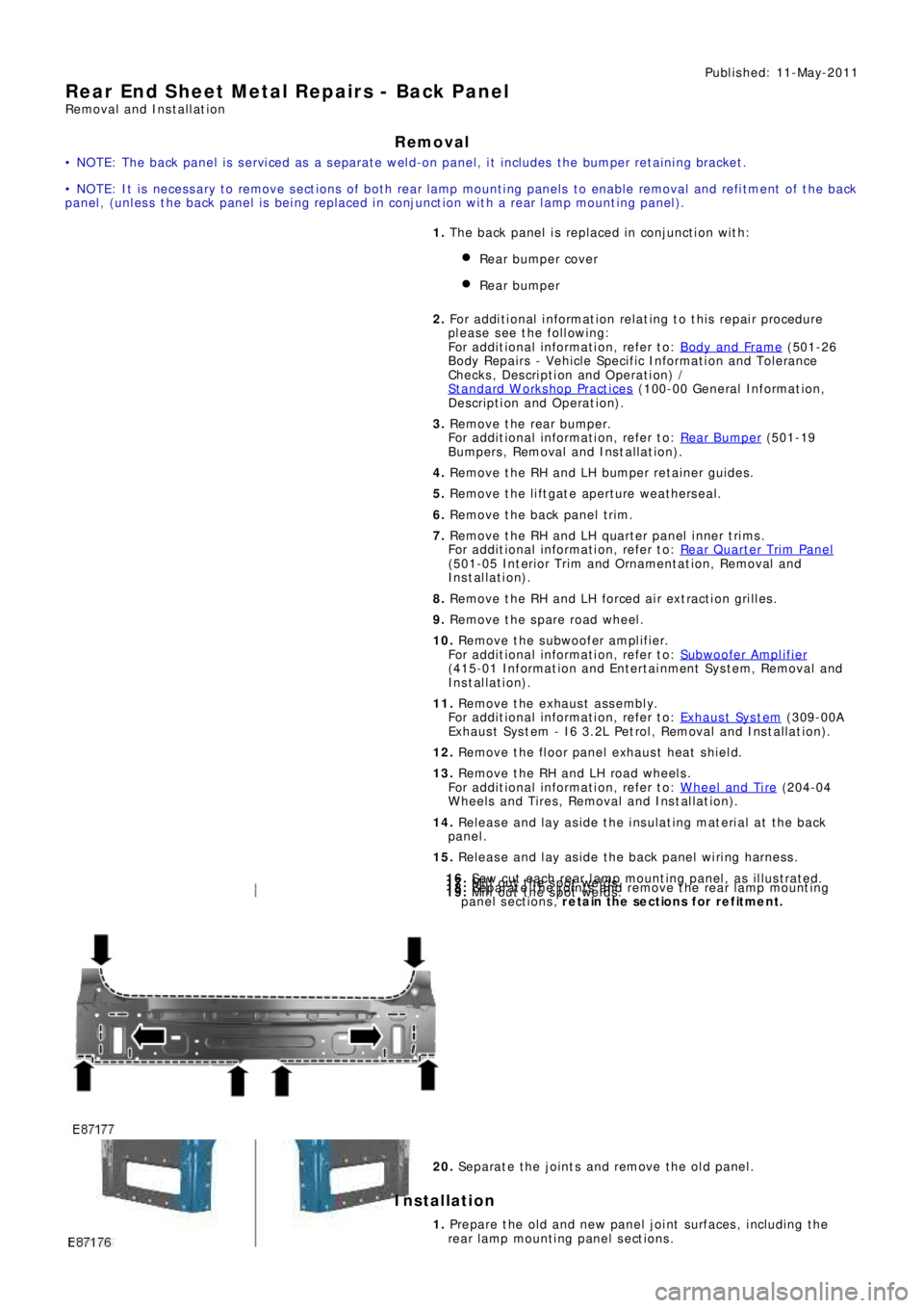
16. Saw cut each rear lamp mounting panel, as illustrated.17. Mill out the spot welds.18. Separate the joints and remove the rear lamp mounting
panel sections, retain the sections for refitment.19. Mill out the spot welds.
20. Separate the joints and remove the old panel.
Installation
1. Prepare the old and new panel joint surfaces, including the
rear l amp mount i ng panel s ect ions .
Page 2658 of 3229
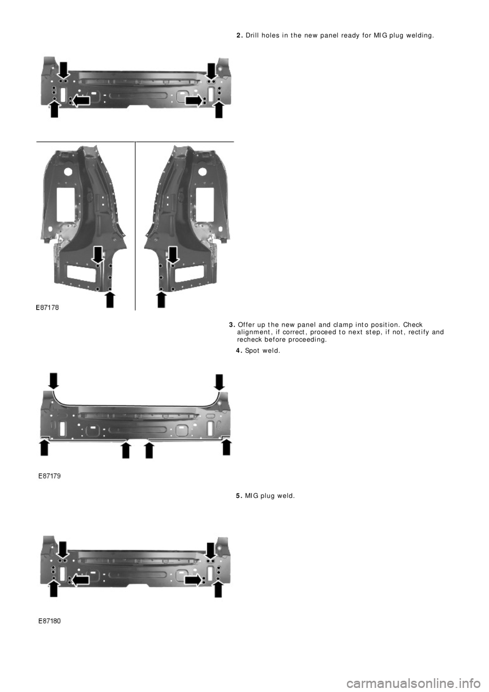
2. Drill holes in the new panel ready for MIG plug welding.
3. Offer up the new panel and clamp into position. Check
al ignment , i f correct , proceed t o next s t ep, i f not , rect i fy and
recheck before proceeding.
4. Sp o t w e l d .
5. MIG pl ug we l d.
Page 2659 of 3229
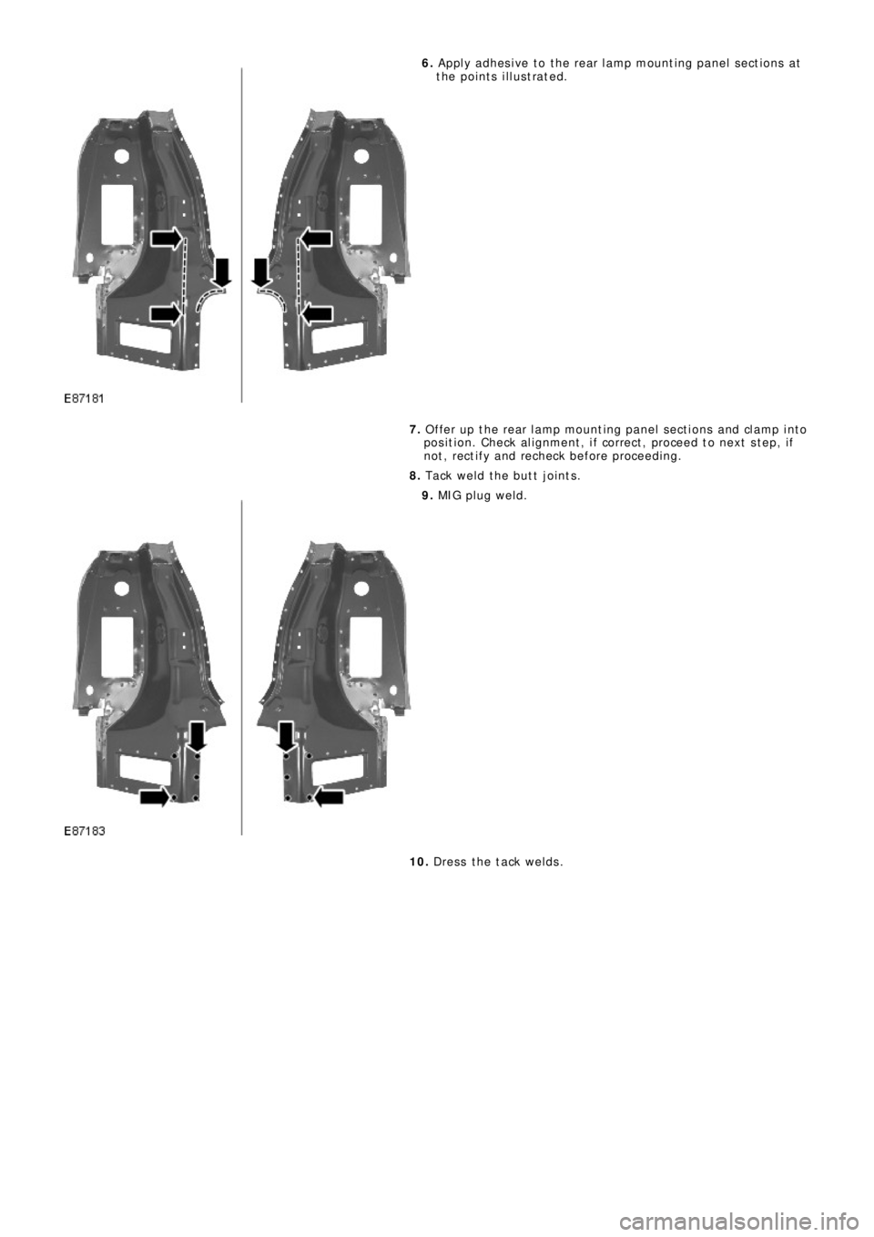
6. Appl y adhes i ve t o t he rear l amp mount i ng panel s ect ions at
the points illustrated.
7. Offer up t he rear l amp mount ing panel s ect i ons and cl amp int o
position. Check alignment, if correct, proceed to next step, if
no t , re ct i f y a nd re che ck b e f o re p ro ce e d i ng .
8. Tack weld the butt joints.
9. MIG pl ug we l d.
10. Dress the tack welds.
Page 2660 of 3229
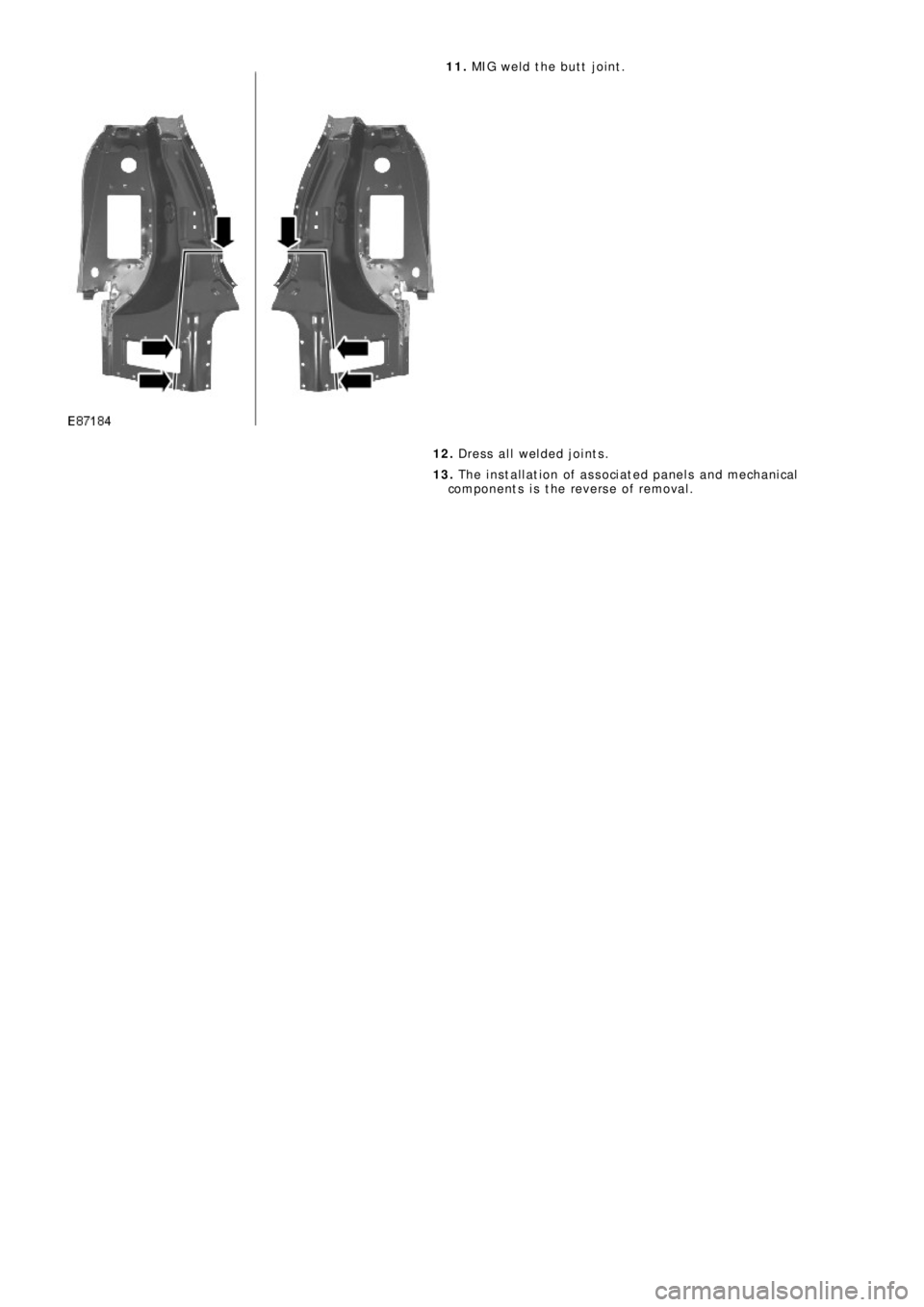
11. MIG weld the butt joint.
12. Dress all welded joints.
13. The installation of associated panels and mechanical
components is the reverse of removal.
Trending: airbag off, spare tire, pairing phone, headrest, roof, washer fluid, open gas tank
