LAND ROVER FRELANDER 2 2006 Repair Manual
FRELANDER 2 2006
LAND ROVER
LAND ROVER
https://www.carmanualsonline.info/img/64/57251/w960_57251-0.png
LAND ROVER FRELANDER 2 2006 Repair Manual
Trending: service indicator, windshield wipers, turn signal bulb, fuel cap, isofix, length, seat memory
Page 2691 of 3229
Publ is hed: 11-May-2011
Rear End Sheet Metal Repairs - Inner Back Panel Assembly
Removal and Installation
Removal
• NOTE: The inner back panel assembly is serviced as a separate weld-on panel.
• NOTE: The panel is serviced less its weld studs.
• NOTE: There are NVH elements attached to the panel, they are not serviced on the new panel. If damaged, new
elements will be required.
• NOTE: It is necessary to remove the back panel and both rear lamp mounting panels to enable removal and refitment of
t he i nner back panel .
1. The inner back panel as s embly is replaced in conjunct ion wit h:
Rear bumper cover
Re a r bumpe r a rma t ure
Back panel
Bot h rear l amp mount ing panel s
2. Fo r a d d i t i o na l i nf o rma t i o n re l a t i ng t o t hi s re p a i r p ro ce d ure
please see the following:
Fo r a d d i t i o na l i nf o rma t i o n, re f e r t o : Body and Frame
(501-26
Body Repairs - Vehicle Specific Information and Tolerance
Checks, Description and Operation) /
St a nd a rd W o rks ho p P ra ct i ce s
(100-00 Ge ne ra l I nf o rma t i o n,
Description and Operation).
3. Re move bot h re a r l a mp mount i ng pa ne l s .
Fo r a d d i t i o na l i nf o rma t i o n, re f e r t o : Rear Lamp Mount i ng Panel
(501-30 Rear End Sheet Metal Repairs, Removal and
Installation).
4. Remove the back panel.
Fo r a d d i t i o na l i nf o rma t i o n, re f e r t o : B a ck P a ne l A s s e mb l y
(501-30, Removal and Ins t al l at i on).
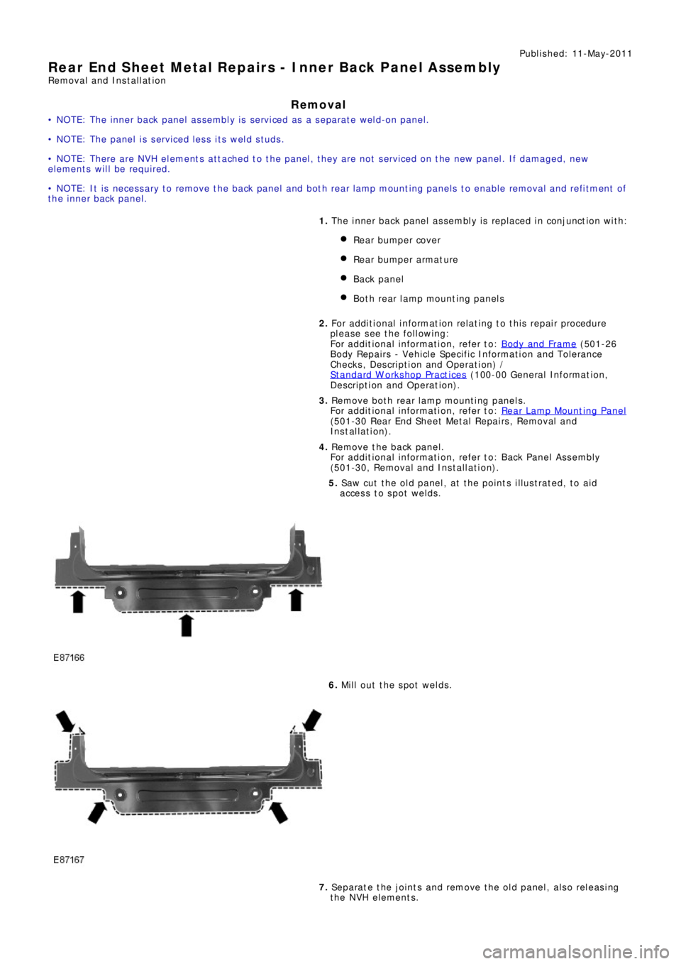
5. Saw cut the old panel, at the points illustrated, to aid
access to spot welds.
6. Mill out the spot welds.
7. Separate the joints and remove the old panel, also releasing
the NVH elements.
Page 2692 of 3229
Installation
1. Prepare the old and new panel joint surfaces.
2. Offer up the new panel and clamp into position. Check
al ignment , i f correct , proceed t o next s t ep, i f not , rect i fy and
recheck before proceeding.
3. Remove the new panel.
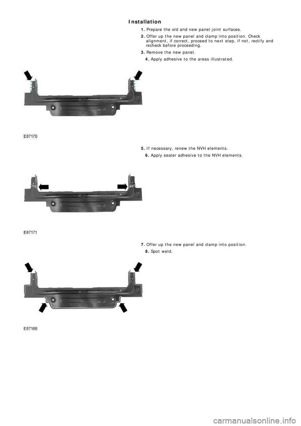
4. Apply adhesive to the areas illustrated.
5. If necessary, renew the NVH elements.
6. Apply sealer adhesive to the NVH elements.
7. Offer up the new panel and clamp into position.
8. Sp o t w e l d .
Page 2693 of 3229
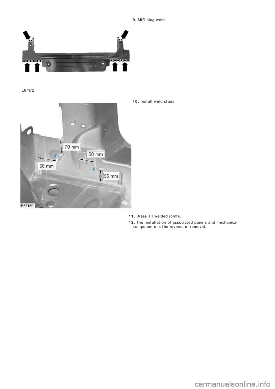
9. MIG pl ug we l d.
10. Install weld studs.
11. Dress all welded joints.
12. The installation of associated panels and mechanical
components is the reverse of removal.
Page 2694 of 3229
Publ is hed: 11-May-2011
Rear End Sheet Metal Repairs - Rear Side Member Upper Side Extension
Removal and Installation
Removal
• NOTE: The rear side member upper side extension is serviced as a separate weld on panel, it is also serviced on the rear
s i de me mbe r.
• NOTE: The panel is serviced less its weld studs. 1. The rear side member upper side extension is replaced in
conjunct ion wit h:
Rear bumper cover
Re a r bumpe r a rma t ure
Rear l amp mount ing panel
Re a r s i de me mbe r l owe r s i de e xt e ns i o n
2. Fo r a d d i t i o na l i nf o rma t i o n re l a t i ng t o t hi s re p a i r p ro ce d ure
please see the following:
Fo r a d d i t i o na l i nf o rma t i o n, re f e r t o : Body and Frame
(501-26
Body Repairs - Vehicle Specific Information and Tolerance
Checks, Description and Operation) /
St a nd a rd W o rks ho p P ra ct i ce s
(100-00 Ge ne ra l I nf o rma t i o n,
Description and Operation).
3. Re move t he re a r s i de me mbe r l o we r s i de e xt e ns i on.
Fo r a d d i t i o na l i nf o rma t i o n, re f e r t o : Rear Side Member Lower
Si d e E xt e n s i o n (501-30 Rear End Sheet Met al Repai rs , Removal
and Installation).
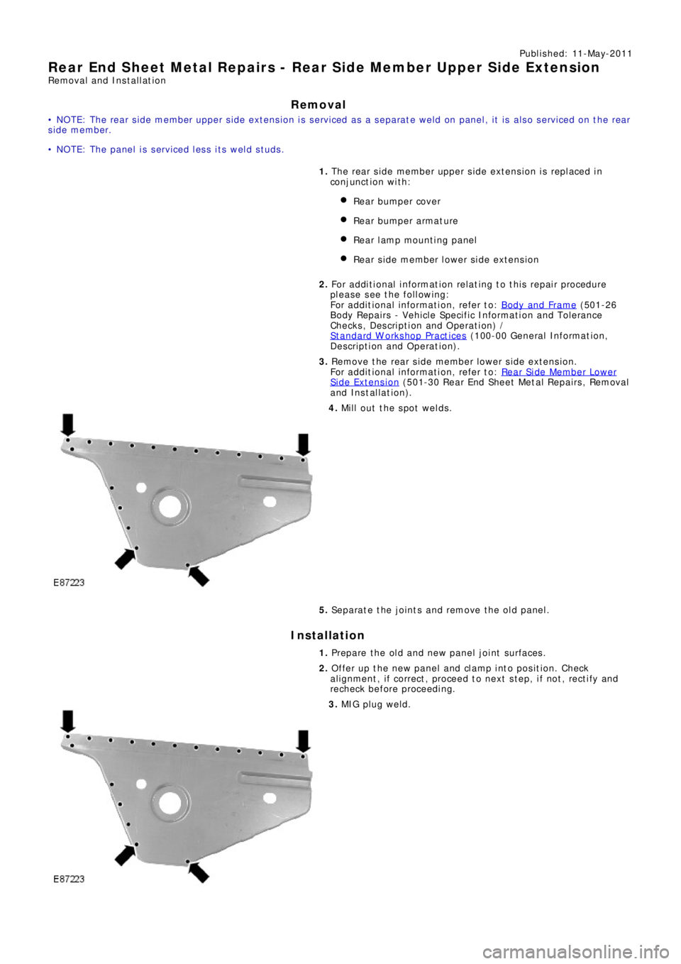
4. Mill out the spot welds.
5. Separate the joints and remove the old panel.
Installation
1. Prepare the old and new panel joint surfaces.
2. Offer up the new panel and clamp into position. Check
al ignment , i f correct , proceed t o next s t ep, i f not , rect i fy and
recheck before proceeding.
3. MIG pl ug we l d.
Page 2695 of 3229
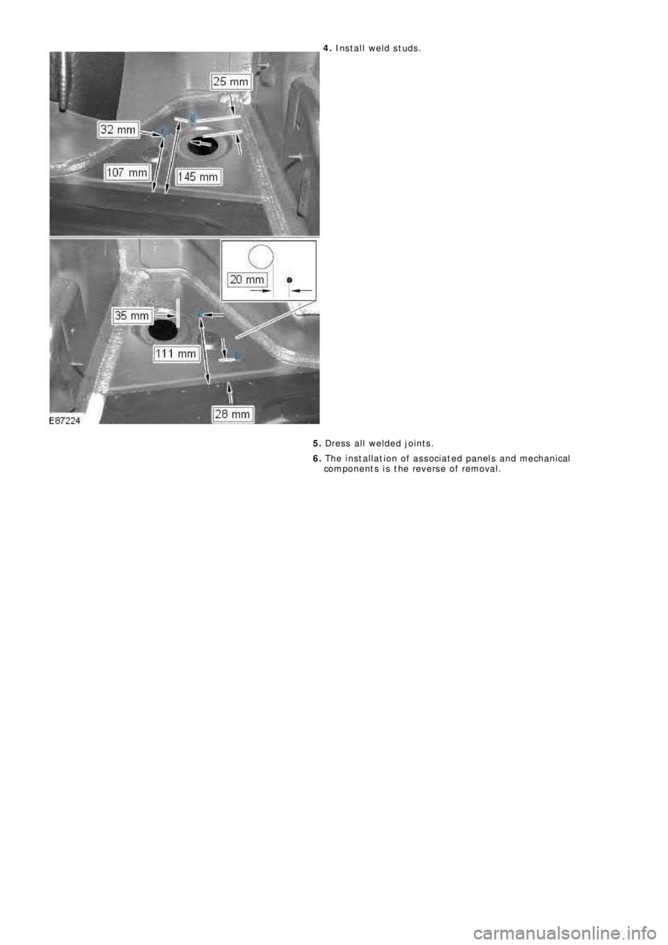
4. Install weld studs.
5. Dress all welded joints.
6. The installation of associated panels and mechanical
components is the reverse of removal.
Page 2696 of 3229
Publ is hed: 11-May-2011
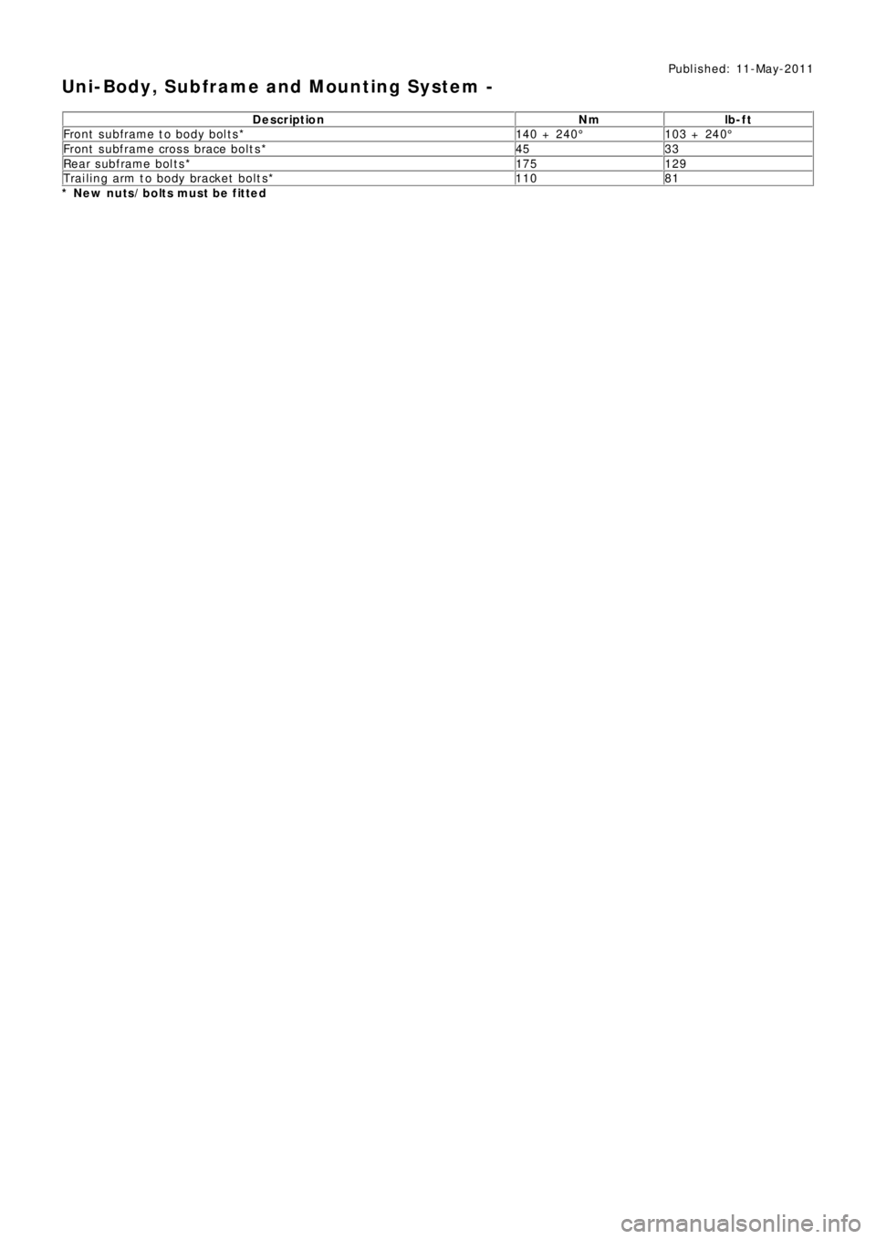
Uni-Body, Subframe and Mounting System -
Description Nm lb-ft
Front s ubframe t o body bol t s * 140 + 240° 103 + 240°
Front subframe cross brace bolts* 45 33
Rear s ubframe bol t s * 175 129
Trailing arm to body bracket bolts* 110 81
* New nuts/bolts must be f itted
Page 2697 of 3229
Publ is hed: 11-May-2011
Uni-Body, Subframe and Mounting System - Front SubframeRemoval and Installation
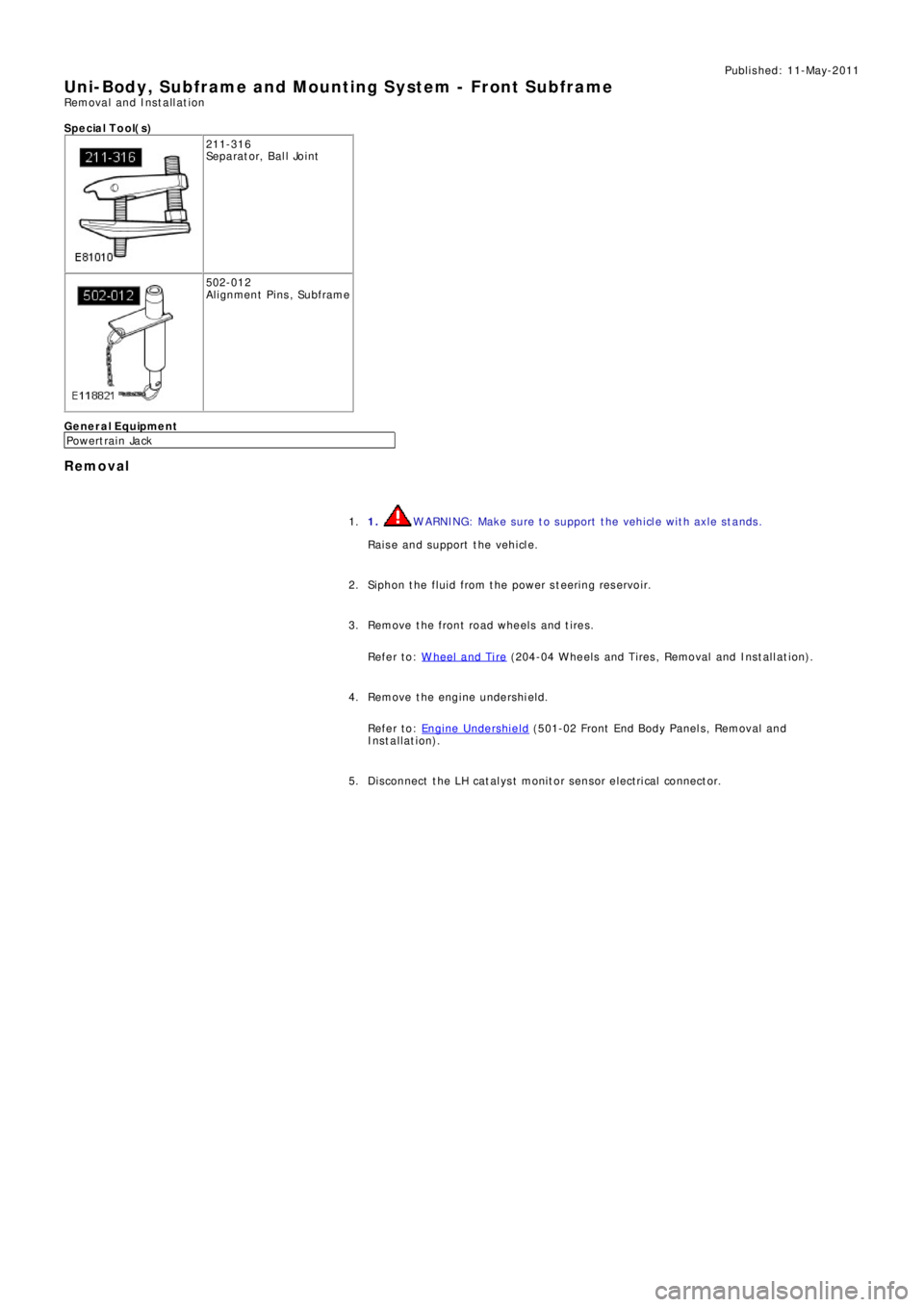
S p e c ia l T o o l( s )
211-316
Se p a ra t o r, B a l l Jo i nt
502-012
Alignment Pins, Subframe
General Equipment
P o we rt ra i n Ja ck
Removal
1. WARNING: Make sure to support the vehicle with axle stands.
Raise and support the vehicle. 1.
Siphon the fluid from the power steering reservoir. 2.
Remove the front road wheels and tires.
Refer to: W heel and Tire
(204-04 W heels and Tires , Removal and Ins t all at i on). 3.
Remove the engine undershield.
Refer to: Engine Undershield
(501-02 Front End Body Panel s, Removal and
Installation). 4.
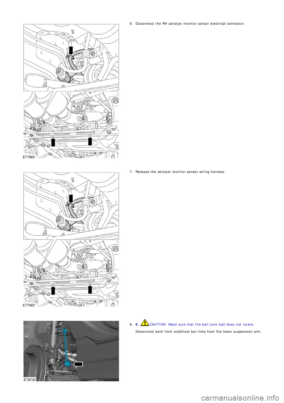
Di sconnect t he LH cat al ys t monit or sens or elect ri cal connect or. 5.
Page 2698 of 3229
Disconnect the RH catalyst monitor sensor electrical connector. 6.
Rel eas e t he cat al ys t monit or sens or wiri ng harness . 7.
8. CAUTION: Make sure that the ball joint ball does not rotate.
Disconnect both front stabilizer bar links from the lower suspension arm. 8.
Page 2699 of 3229
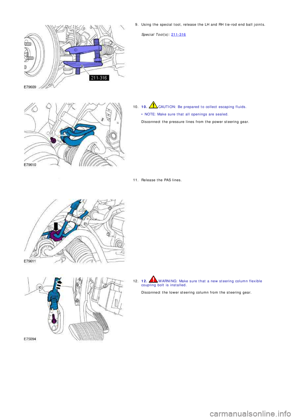
Using the special tool, release the LH and RH tie-rod end ball joints.
Special Tool(s): 211-3169.
10. CAUTION: Be prepared to collect escaping fluids.
• NOTE: Make sure that all openings are sealed.
Disconnect the pressure lines from the power steering gear. 10.
Release the PAS lines. 11.
12. WARNING: Make sure that a new steering column flexible
coupling bolt is installed.
Disconnect the lower steering column from the steering gear. 12.
Page 2700 of 3229
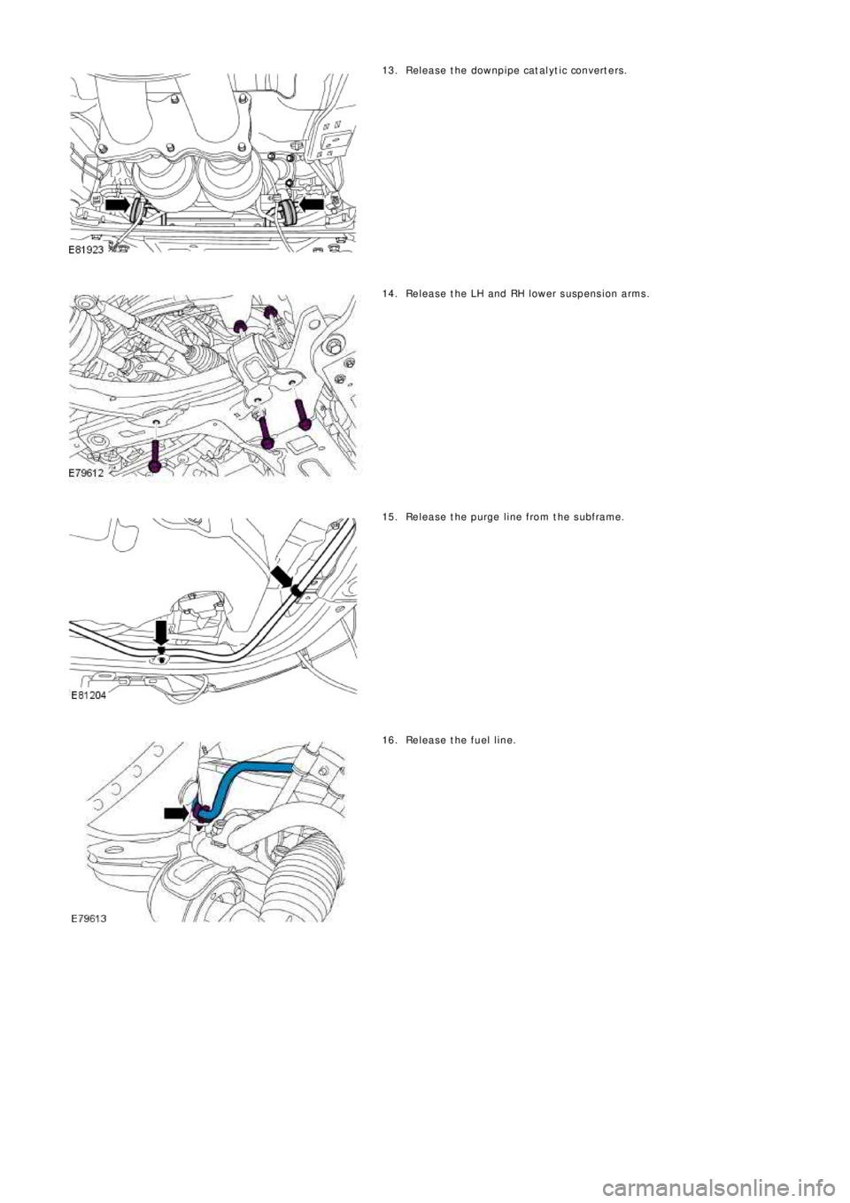
Release the downpipe catalyt ic convert ers. 13.
Release the LH and RH lower suspension arms. 14.
Release the purge line from the subframe. 15.
Release the fuel line. 16.
Trending: service schedule, spare tire location, language, oil type, buttons, diagram, warning

