LAND ROVER FRELANDER 2 2006 Repair Manual
FRELANDER 2 2006
LAND ROVER
LAND ROVER
https://www.carmanualsonline.info/img/64/57251/w960_57251-0.png
LAND ROVER FRELANDER 2 2006 Repair Manual
Trending: open hood, ABS, oil additives, spare tire, check oil, parking sensors, fuel cap release
Page 2711 of 3229
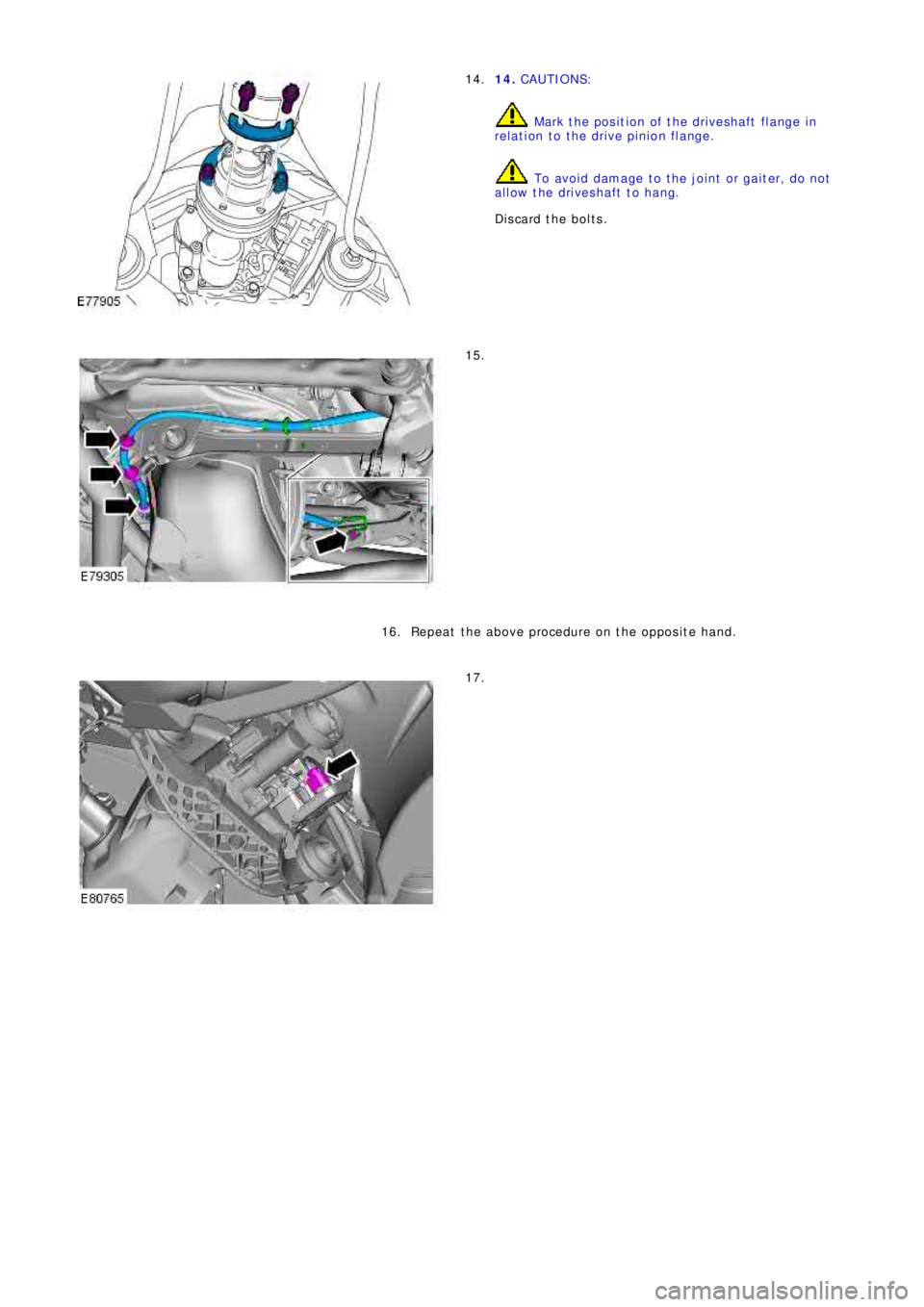
14. CAUTIONS:
Mark the position of the driveshaft flange in
relation to the drive pinion flange.
To avoid damage to the joint or gaiter, do not
allow the driveshaft to hang.
Discard the bolts. 14.
15.
Repeat the above procedure on the opposite hand. 16.
17.
Page 2712 of 3229
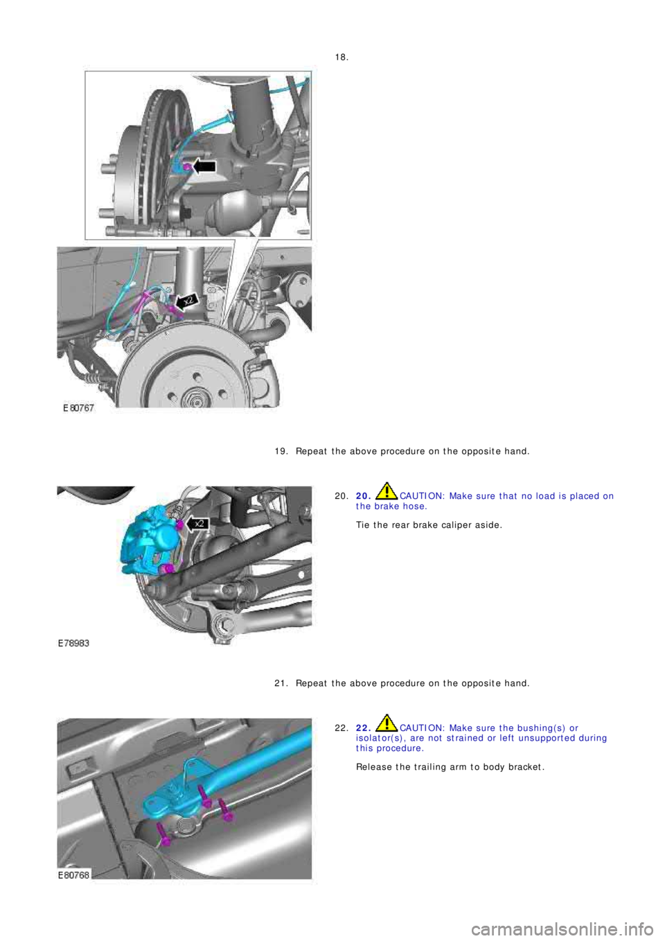
18.
Repeat the above procedure on the opposite hand. 19.
20. CAUTION: Make sure that no load is placed on
the brake hose.
Tie the rear brake caliper aside. 20.
Repeat the above procedure on the opposite hand. 21.
22. CAUTION: Make sure the bushing(s) or
isolator(s), are not strained or left unsupported during
this procedure.
Release the trailing arm to body bracket. 22.
Page 2713 of 3229
Repeat the above procedure on the opposite hand. 23.
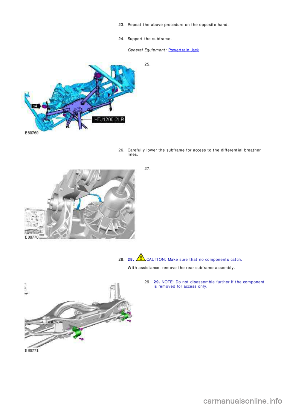
Support the subframe.
General Equi pment : P o w e rt ra i n Ja ck
24.
25.
Ca re f ul l y l o w e r t he s ub f ra me f o r a cce s s t o t he d i f f e re nt i a l b re a t he r
lines. 26.
27.
28.
CAUTION: Make sure that no components catch.
With assistance, remove the rear subframe assembly. 28.
29. NOTE: Do not disassemble further if the component
i s re mo ve d f o r a cce s s o nl y. 29.
Page 2714 of 3229
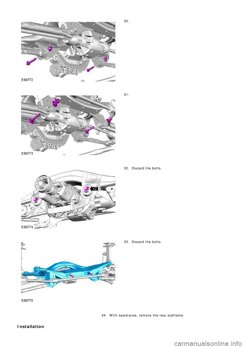
30.
31.
Discard the bolts. 32.
Discard the bolts. 33.
With assistance, remove the rear subframe. 34.
Installation
Page 2715 of 3229
1. CAUTION: Make sure that new bolts are installed.
Clean the component mating faces.
With assistance, install the subframe.With assistance, align and secure the differential.Tighten the rear bolts.
Torque: 110 Nm
Tighten the front bolts.
Torque: 175 Nm
1.
2.
CAUTION: Make sure that new bolts are installed.
Align the suspension arms to the subframe and install the bolts, do
not fully tighten at this stage. 2.
Using the special tool, support the subframe. 3.
Connect the transmission breather lines. 4.
5. CAUTIONS:
Make sure that no components catch.
Make sure that new bolts are installed.
With assistance, position the subframe to the body and tighten the
bolts.
Torque: 175 Nm
5.
6.
CAUTION: Make sure that new bolts are installed.
Install the stabilizer clamp bolts, but do not tighten fully at this
stage. 6.
Connect the Active On-demand Coupling module electrical connector. 7.
Re mo ve t he p o we rt ra i n j a ck.
General Equi pment : P o w e rt ra i n Ja ck
8.
9.
CAUTION: Make sure that new bolts are installed.
Install the trailing arm to body brackets.
Torque: 110 Nm9.
10.
CAUTION: Make sure that the brake hose is not twisted
and is correctly located.
Clean the component mating faces.
Install the brake caliper anchor plate.
Torque: 110 Nm
Repeat the above procedure for the other side.
10.
Secure the wheel speed sensor and lead.
11.
Page 2716 of 3229
Torque: 5 NmSecure the lead in the clips.Repeat the above procedure for the other side.
LH side: Connect the ride height sensor electrical connector. 12.
Position and secure the rear shock absorbers.
Install both mass dampers.
Torque: 25 Nm
Repeat the above procedure for the other side.
13.
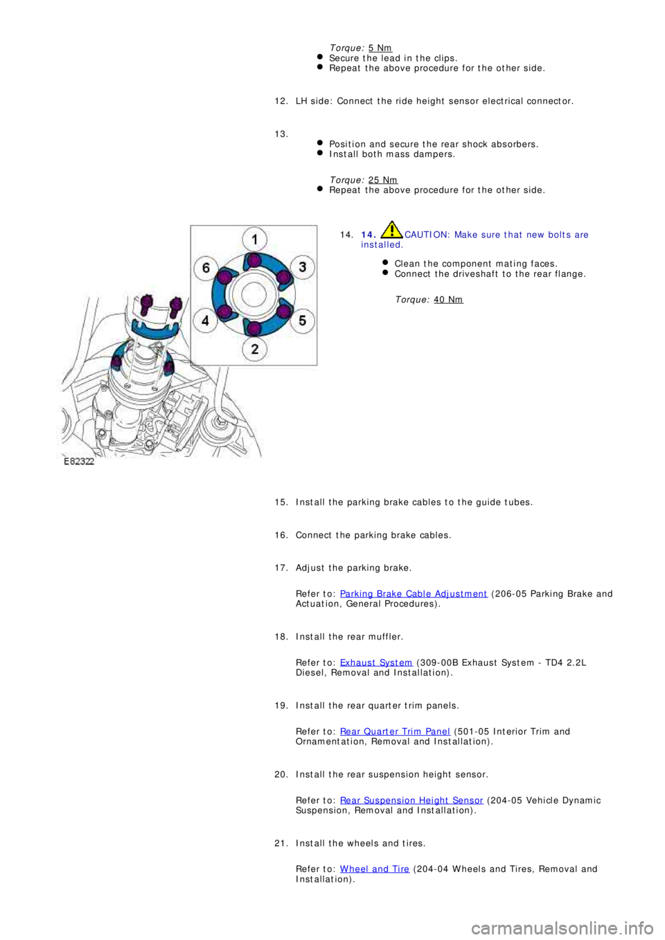
14. CAUTION: Make sure that new bolts are
installed.
Clean the component mating faces.
Connect the driveshaft to the rear flange.
Torque: 40 Nm
14.
Install the parking brake cables to the guide tubes. 15.
Connect the parking brake cables. 16.
Adjust the parking brake.
Refer to: Parking Brake Cable Adjustment
(206-05 Parki ng Brake and
Act uat i on, General Procedures ). 17.
Install the rear muffler.
Refer to: Exhaus t Sys t em
(309-00B Exhaus t Sys t em - TD4 2.2L
Diesel, Removal and Installation). 18.
Install the rear quarter trim panels.
Refer to: Rear Quarter Trim Panel
(501-05 Int eri or Tri m and
Ornament at i on, Removal and Ins t al lat i on). 19.
Install the rear suspension height sensor.
Refer to: Rear Suspension Height Sensor
(204-05 Vehi cl e Dynami c
Suspension, Removal and Installation). 20.
Install the wheels and tires.
Refer to: Wheel and Tire
(204-04 Wheels and Tires, Removal and
Installation). 21.
Page 2717 of 3229
22. CAUTION: Nuts and bolts must be tightened with the
weight of the vehicle on the suspension.
Tighten the stabilizer bar clamp bolts.
Torque: 60 Nm22.
23.
CAUTION: Nuts and bolts must be tightened with the
weight of the vehicle on the suspension.
Tighten the supsension arms to the subframe.
Torque: 175 Nm
During installation, do not tighten the nuts and bolts until
the 4 wheel alignment procedure has been carried out.
23.
Carry out a complete vehicle geometry check and adjustment. 24.
Page 2718 of 3229
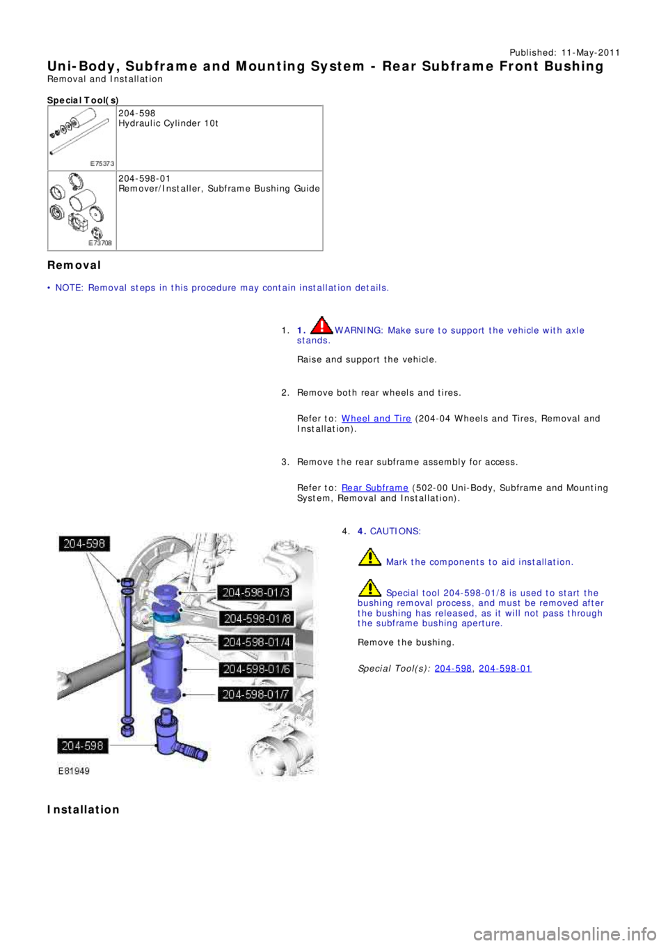
Publ is hed: 11-May-2011
Uni-Body, Subframe and Mounting Syst em - Rear Subframe Front Bushing
Removal and Installation
S p e c ia l T o o l( s )
204-598
Hydraulic Cylinder 10t
204-598-01
Re mo ve r/I ns t a l l e r, Sub f ra me B us hi ng Gui d e
Removal
• NOTE: Removal steps in this procedure may contain installation details.
1.
WARNING: Make sure to support the vehicle with axle
stands.
Raise and support the vehicle.
1.
Remove both rear wheels and tires.
Refer to: Wheel and Tire
(204-04 Wheels and Tires, Removal and
Installation).
2.
Remove the rear subframe assembly for access.
Refer to: Rear Subframe
(502-00 Uni -Body, Subframe and Mount i ng
System, Removal and Installation).
3.
4.
CAUTIONS:
Mark the components to aid installation.
Speci al t ool 204-598-01/8 i s us ed t o s t art t he
bushing removal process, and must be removed after
the bushing has released, as it will not pass through
the subframe bushing aperture.
Remove the bushing.
Special Tool(s): 204-598
, 204-598-01
4.
Installation
Page 2719 of 3229
1. CAUTIONS:
Make sure the correct special tool is used to
install the bushings to the correct depth.
Make sure that the installation marks are
aligned.
Install the bushing.
Special Tool(s): 204-598
, 204-598-01
1.
Install the rear subframe assembly.
Refer to: Rear Subframe
(502-00 Uni -Body, Subframe and Mount i ng
System, Removal and Installation).
2.
Install the wheels and tires.
Refer to: Wheel and Tire
(204-04 Wheels and Tires, Removal and
Installation).
3.
Page 2720 of 3229
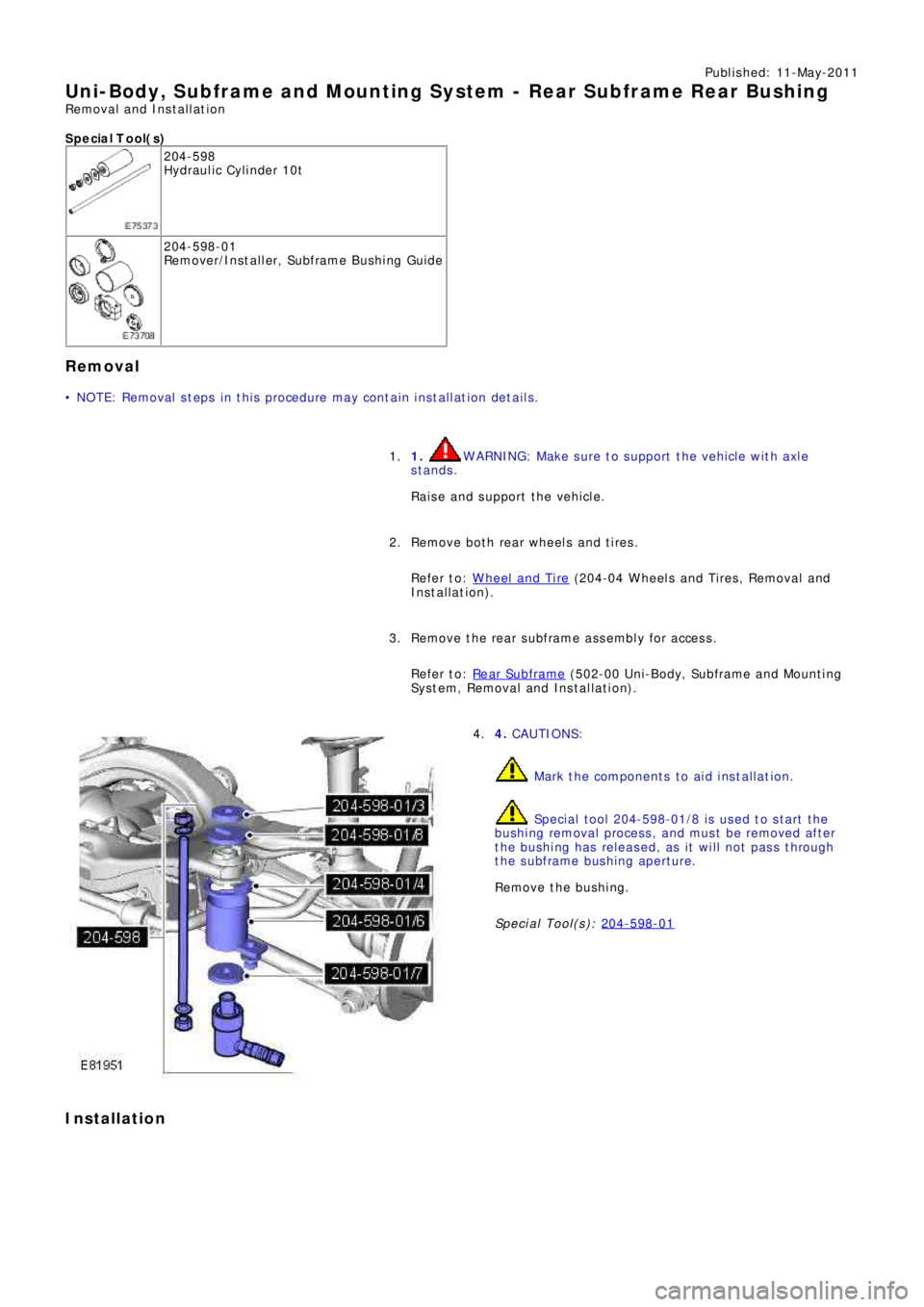
Publ is hed: 11-May-2011
Uni-Body, Subframe and Mounting Syst em - Rear Subframe Rear Bushing
Removal and Installation
S p e c ia l T o o l( s )
204-598
Hydraulic Cylinder 10t
204-598-01
Re mo ve r/I ns t a l l e r, Sub f ra me B us hi ng Gui d e
Removal
• NOTE: Removal steps in this procedure may contain installation details.
1.
WARNING: Make sure to support the vehicle with axle
stands.
Raise and support the vehicle.
1.
Remove both rear wheels and tires.
Refer to: Wheel and Tire
(204-04 Wheels and Tires, Removal and
Installation).
2.
Remove the rear subframe assembly for access.
Refer to: Rear Subframe
(502-00 Uni -Body, Subframe and Mount i ng
System, Removal and Installation).
3.
4.
CAUTIONS:
Mark the components to aid installation.
Speci al t ool 204-598-01/8 i s us ed t o s t art t he
bushing removal process, and must be removed after
the bushing has released, as it will not pass through
the subframe bushing aperture.
Remove the bushing.
Special Tool(s): 204-598-01
4.
Installation
Trending: oil pressure, tire pressure, fuse box location, differential, cruise control, automatic transmission, wheel bolts
