LAND ROVER FRELANDER 2 2006 Repair Manual
Manufacturer: LAND ROVER, Model Year: 2006, Model line: FRELANDER 2, Model: LAND ROVER FRELANDER 2 2006Pages: 3229, PDF Size: 78.5 MB
Page 391 of 3229
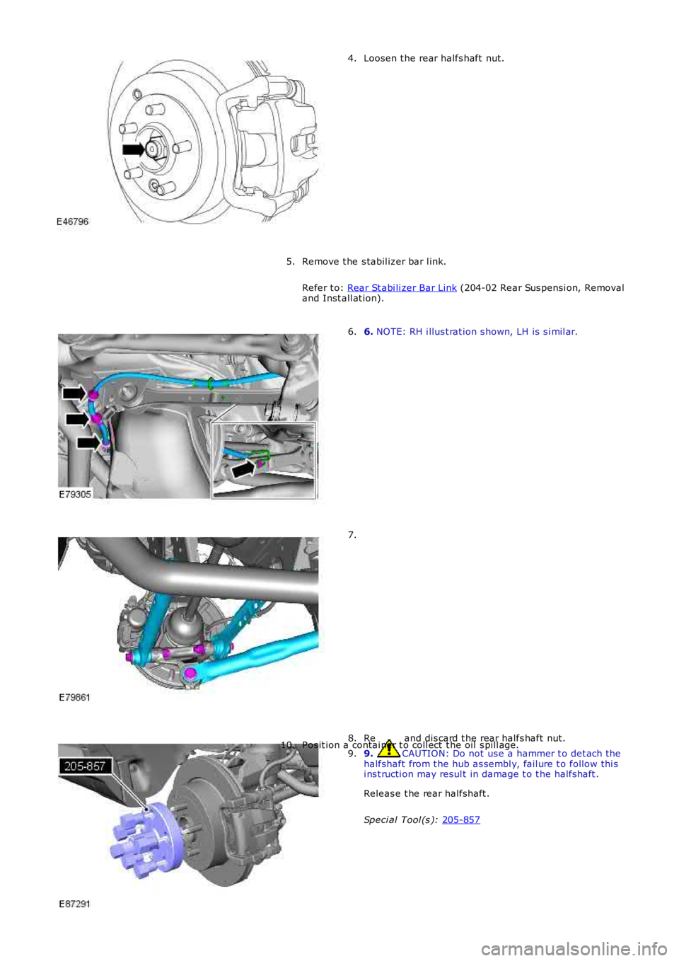
Loosen t he rear halfs haft nut.
4.
Remove t he s tabil izer bar l ink.
Refer t o: Rear St abi li zer Bar Link (204-02 Rear Sus pensi on, Removal
and Inst all at ion).
5. 6.
NOTE: RH i llus t rat ion s hown, LH is s i mil ar.
6. 7.
Remove and dis card t he rear halfs haft nut.
8. 9. CAUTION: Do not us e a hammer t o det ach t he
halfshaft from t he hub as sembl y, fail ure t o follow thi s
i ns t ructi on may resul t in damage t o t he halfshaft .
Releas e t he rear halfshaft .
Speci al Tool (s ): 205-857 9.
Pos it ion a contai ner t o coll ect t he oil s pill age.
10.
Page 392 of 3229
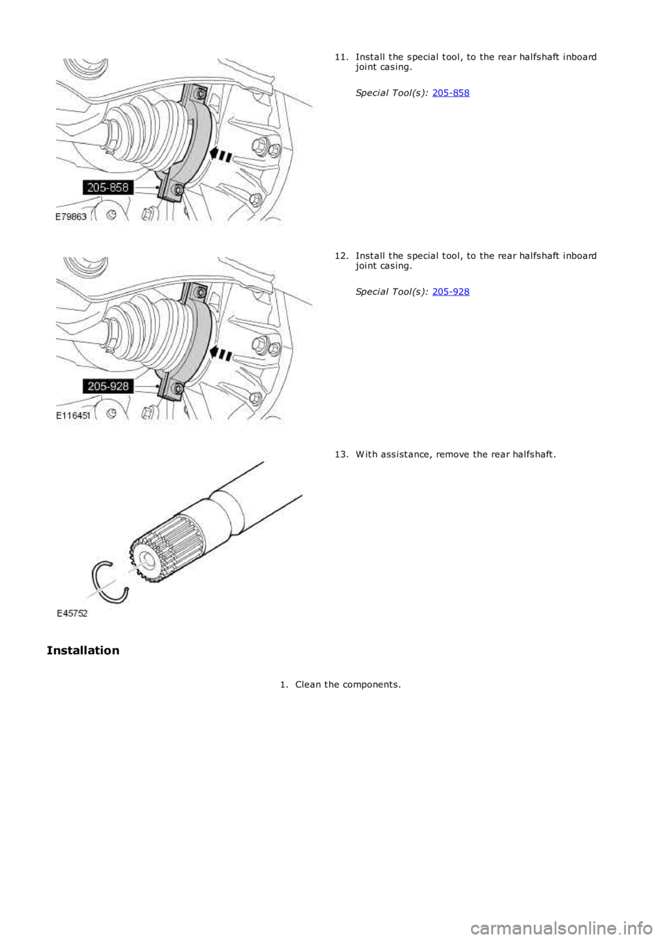
Inst all t he s pecial t ool , to the rear hal fs haft i nboard
joi nt cas ing.
Speci al Tool (s ): 205-858 11.
Inst all t he s pecial t ool , to the rear hal fs haft i nboard
joi nt cas ing.
Speci al Tool (s ): 205-928 12.
W it h ass i st ance, remove the rear hal fs haft .
13.
Installation Clean t he component s.
1.
Page 393 of 3229
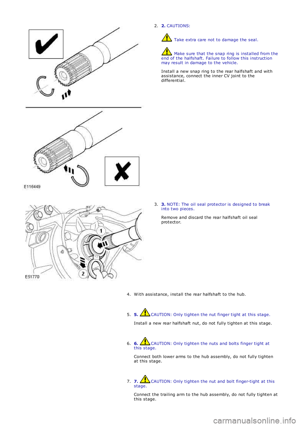
2. CAUTIONS:
Take extra care not t o damage t he s eal .
Make s ure that t he s nap ri ng is i nst all ed from t heend of t he hal fs haft . Fai lure to fol low t his i nst ruct ionmay res ul t in damage to t he vehicle.
Inst all a new snap ring t o t he rear halfs haft and wit has si s tance, connect t he inner CV joi nt to thedifferent ial .
2.
3. NOTE: The oil s eal prot ector is des igned t o breaki nt o t wo pi eces .
Remove and dis card t he rear halfs haft oil s ealprot ect or.
3.
W it h ass i st ance, i ns t all the rear hal fs haft t o t he hub.4.
5. CAUTION: Only ti ght en t he nut fi nger t ight at thi s s tage.
Inst all a new rear hal fs haft nut , do not full y t ighten at t his s t age.
5.
6. CAUTION: Only ti ght en t he nuts and bolt s finger ti ght att his s t age.
Connect both lower arms to the hub as s embly, do not full y t ightenat t hi s s tage.
6.
7. CAUTION: Only ti ght en t he nut and bol t fi nger-t ight at t hi ss tage.
Connect t he trail ing arm t o t he hub as sembl y, do not fully ti ght en att his s t age.
7.
Page 394 of 3229
Stage 1:
Stage 2:
Secure t he parking brake cable.
8.
Support the weight of the vehicle us i ng a jack under the rear hub.
9.
10. CAUTIONS: Nut s and bolt s mus t be t ightened wi th the wei ght of t he
vehicle on the s us pens ion. Do not us e ai r tools to i nst all t he nut. Fail ure t o follow thi s
i ns t ructi on may resul t in damage t o t he component.
Tight en bot h l ower arm nut s and bolt s .
T orque: 175 Nm Tight en the trai li ng arm nut and bol t.
T orque: 270 Nm Tight en the rear hal fs haft nut .
T orque: 330 Nm 30°
St ake t he hub nut.10.
Inst all t he s tabil izer bar l ink.
Refer t o: Rear St abi li zer Bar Link (204-02 Rear Sus pensi on, Removal
and Inst all at ion).
11.
Inst all t he wheel and t ire.
Refer t o: W heel and Ti re (204-04 W heel s and Tires, Removal and
Inst all at ion).
12.
13. CAUTION: Do not fill t he different ial wi th lubri cant up t o
t he fi ll er pl ug. The fil ler plug i s only us ed t o fill t he different ial wi th
l ubricant , and not to act as a level i ndicat or.
Fil l the di fferenti al wi th the correct amount of l ubricant .
Refer t o: Different ial Drai ni ng and Fil ling (205-02 Rear Drive
Axle/Different ial, General Procedures).
13.
Page 395 of 3229
Publi s hed: 18-May-2011
Rear Drive Halfshafts - Rear Halfshaft RH
Removal and Inst all ati on
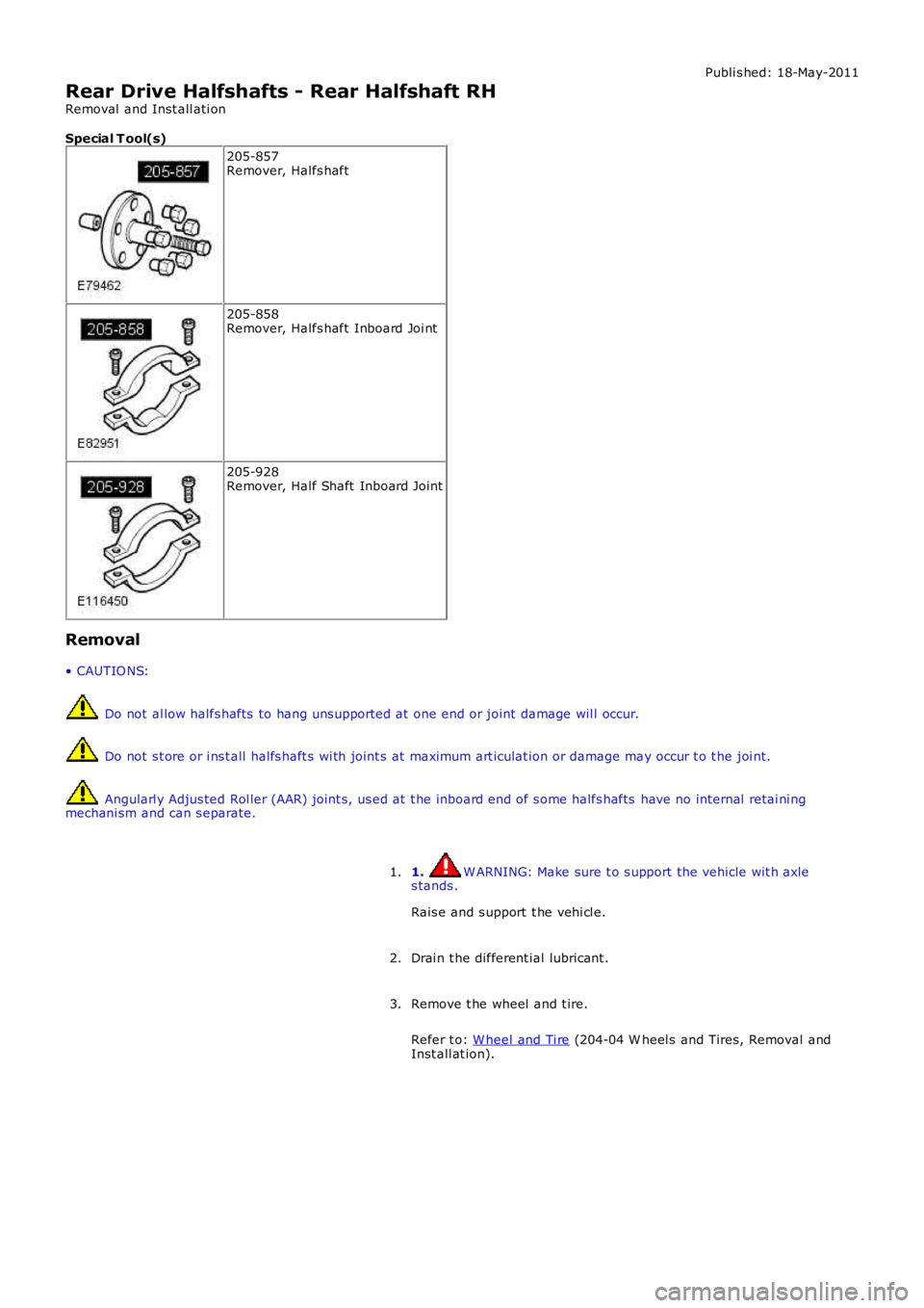
Special T ool(s)
205-857Remover, Halfs haft
205-858Remover, Halfs haft Inboard Joi nt
205-928Remover, Half Shaft Inboard Joint
Removal
• CAUTIO NS:
Do not al low halfs hafts to hang uns upported at one end or joint damage wil l occur.
Do not s t ore or i ns t all halfs haft s wi th joint s at maximum art iculat ion or damage may occur t o t he joi nt.
Angularl y Adjus ted Rol ler (AAR) joint s, us ed at t he inboard end of s ome halfs hafts have no internal retai ni ngmechani sm and can s eparate.
1. W ARNING: Make sure t o s upport the vehicle wit h axles tands .
Rais e and s upport t he vehi cl e.
1.
Drai n t he different ial lubricant .2.
Remove t he wheel and t ire.
Refer t o: W heel and Ti re (204-04 W heel s and Tires, Removal andInst all at ion).
3.
Page 396 of 3229
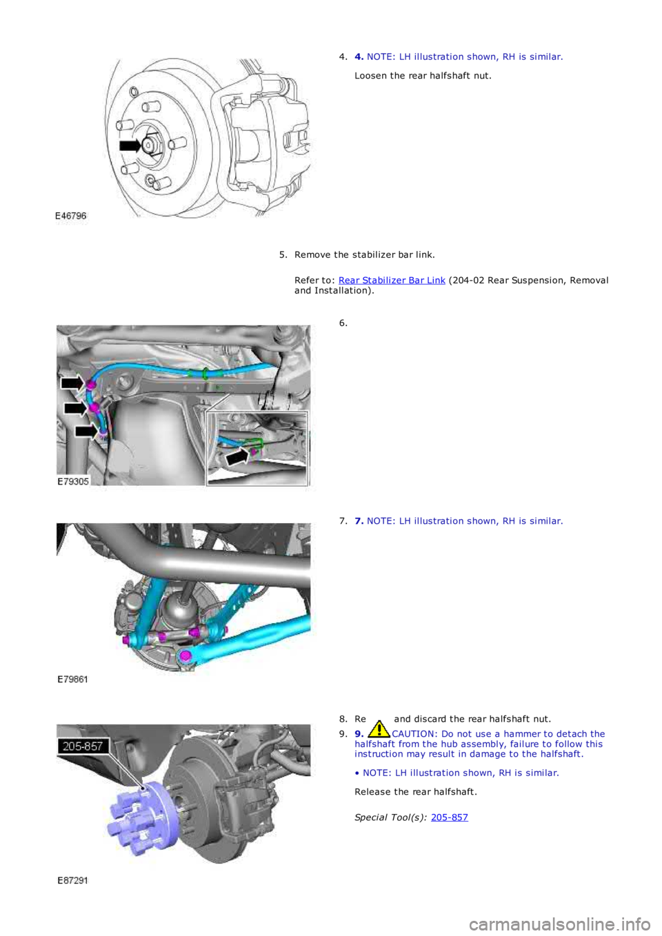
4.
NOTE: LH il lus trati on s hown, RH is s i mil ar.
Loosen t he rear halfs haft nut.
4.
Remove t he s tabil izer bar l ink.
Refer t o: Rear St abi li zer Bar Link (204-02 Rear Sus pensi on, Removal
and Inst all at ion).
5. 6.
7.
NOTE: LH il lus trati on s hown, RH is s i mil ar.
7. Remove and dis card t he rear halfs haft nut.
8. 9. CAUTION: Do not us e a hammer t o det ach t he
halfshaft from t he hub as sembl y, fail ure t o follow thi s
i ns t ructi on may resul t in damage t o t he halfshaft .
• NOTE: LH i ll ust rat ion s hown, RH i s s imi lar.
Releas e t he rear halfshaft .
Speci al Tool (s ): 205-857 9.
Page 397 of 3229
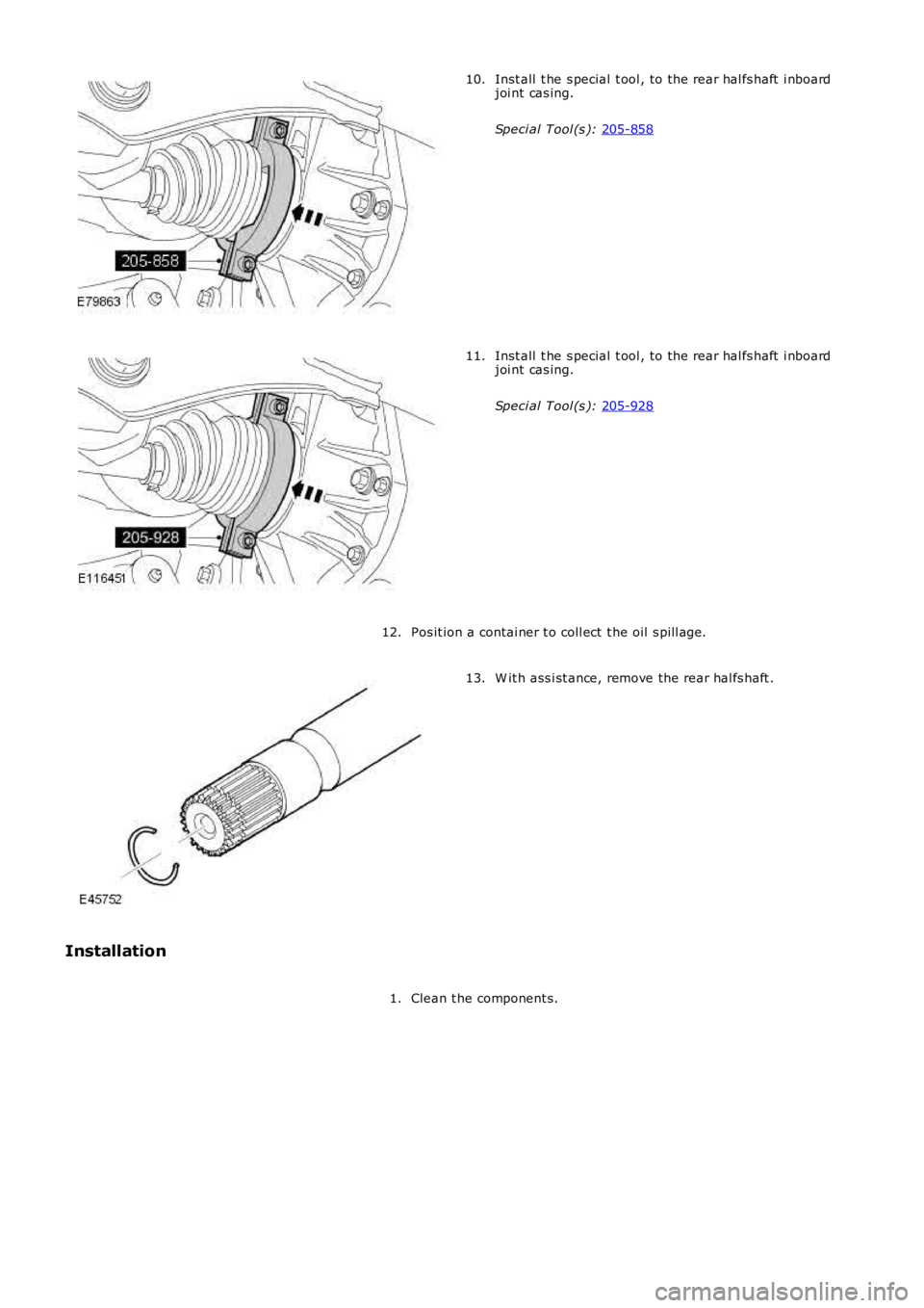
Inst all t he s pecial t ool , to the rear hal fs haft i nboard
joi nt cas ing.
Speci al Tool (s ): 205-858 10.
Inst all t he s pecial t ool , to the rear hal fs haft i nboard
joi nt cas ing.
Speci al Tool (s ): 205-928 11.
Pos it ion a contai ner t o coll ect t he oil s pill age.
12. W it h ass i st ance, remove the rear hal fs haft .
13.
Installation Clean t he component s.
1.
Page 398 of 3229
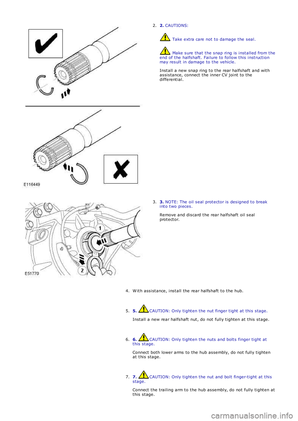
2. CAUTIONS:
Take extra care not t o damage t he s eal .
Make s ure that t he s nap ri ng is i nst all ed from t heend of t he hal fs haft . Fai lure to fol low t his i nst ruct ionmay res ul t in damage to t he vehicle.
Inst all a new snap ring t o t he rear halfs haft and wit has si s tance, connect t he inner CV joi nt to thedifferent ial .
2.
3. NOTE: The oil s eal prot ector is des igned t o breaki nt o t wo pi eces .
Remove and dis card t he rear halfs haft oil s ealprot ect or.
3.
W it h ass i st ance, i ns t all the rear hal fs haft t o t he hub.4.
5. CAUTION: Only ti ght en t he nut fi nger t ight at thi s s tage.
Inst all a new rear hal fs haft nut , do not full y t ighten at t his s t age.
5.
6. CAUTION: Only ti ght en t he nuts and bolt s finger ti ght att his s t age.
Connect both lower arms to the hub as s embly, do not full y t ightenat t hi s s tage.
6.
7. CAUTION: Only ti ght en t he nut and bol t fi nger-t ight at t hi ss tage.
Connect t he trail ing arm t o t he hub as sembl y, do not fully ti ght en att his s t age.
7.
Page 399 of 3229
Stage 1:
Stage 2:
Secure t he parking brake cable.
8.
Support the weight of the vehicle us i ng a jack under the rear hub.
9.
10. CAUTIONS: Nut s and bolt s mus t be t ightened wi th the wei ght of t he
vehicle on the s us pens ion. Do not us e ai r tools to i nst all t he nut. Fail ure t o follow thi s
i ns t ructi on may resul t in damage t o t he component.
Tight en bot h l ower arm nut s and bolt s .
T orque: 175 Nm Tight en the trai li ng arm nut and bol t.
T orque: 270 Nm Tight en the rear hal fs haft nut .
T orque: 330 Nm 30°
St ake t he hub nut.10.
Inst all t he s tabil izer bar l ink.
Refer t o: Rear St abi li zer Bar Link (204-02 Rear Sus pensi on, Removal
and Inst all at ion).
11.
Inst all t he wheel and t ire.
Refer t o: W heel and Ti re (204-04 W heel s and Tires, Removal and
Inst all at ion).
12.
13. CAUTION: Do not fill t he different ial wi th lubri cant up t o
t he fi ll er pl ug. The fil ler plug i s only us ed t o fill t he different ial wi th
l ubricant , and not to act as a level i ndicat or.
Fil l the di fferenti al wi th the correct amount of l ubricant .
13.
Page 400 of 3229
Publi s hed: 11-May-2011
Rear Drive Halfshafts - Inner Constant Velocity (CV) Joint Boot
Removal and Inst all ati on
Special T ool(s)
303-D121Pull er, General Purpose
Removal
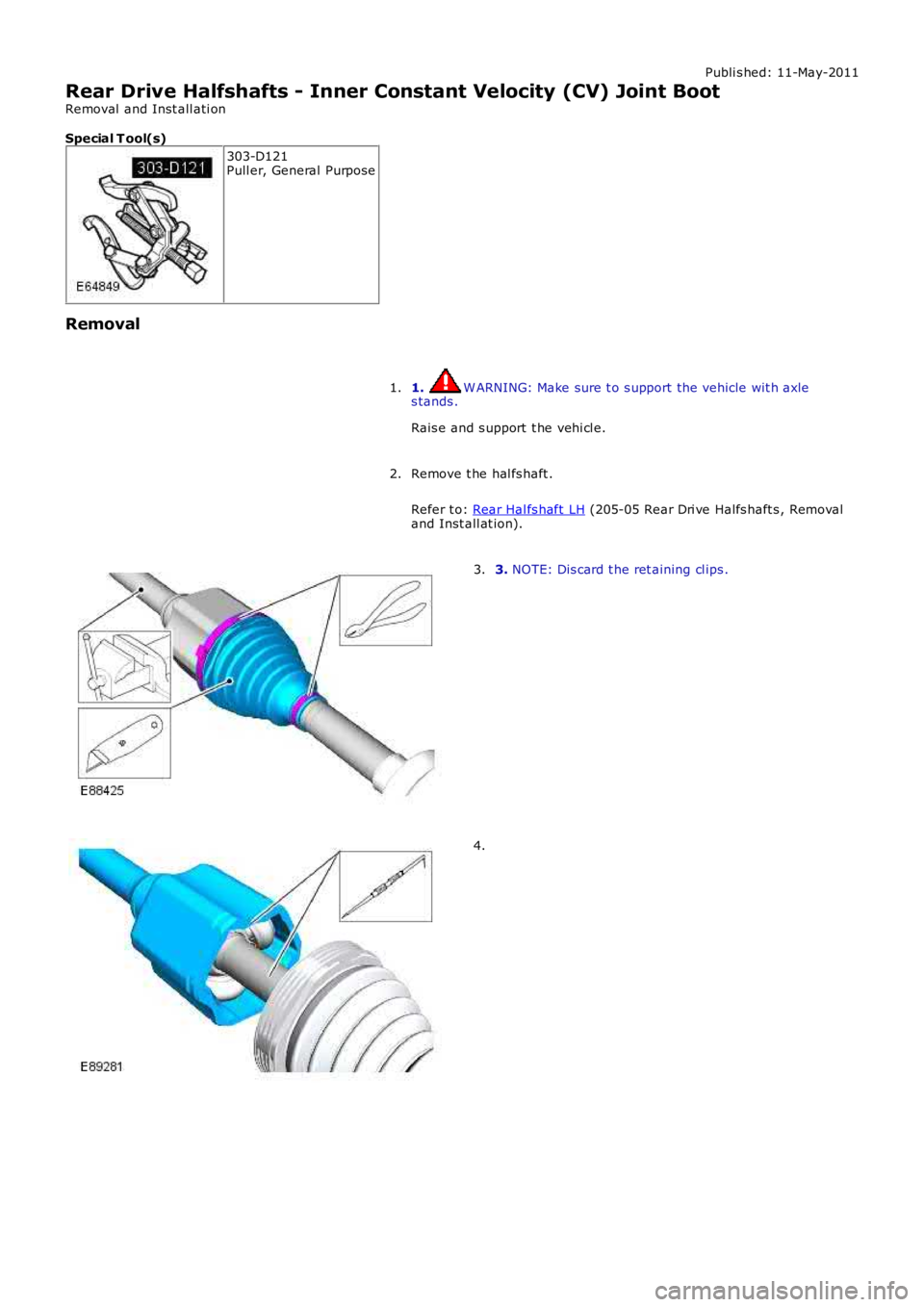
1. W ARNING: Make sure t o s upport the vehicle wit h axles tands .
Rais e and s upport t he vehi cl e.
1.
Remove t he hal fs haft .
Refer t o: Rear Hal fs haft LH (205-05 Rear Dri ve Halfs haft s , Removaland Inst all at ion).
2.
3. NOTE: Dis card t he ret aining cl ips .3.
4.