LAND ROVER FRELANDER 2 2006 Repair Manual
Manufacturer: LAND ROVER, Model Year: 2006, Model line: FRELANDER 2, Model: LAND ROVER FRELANDER 2 2006Pages: 3229, PDF Size: 78.5 MB
Page 471 of 3229
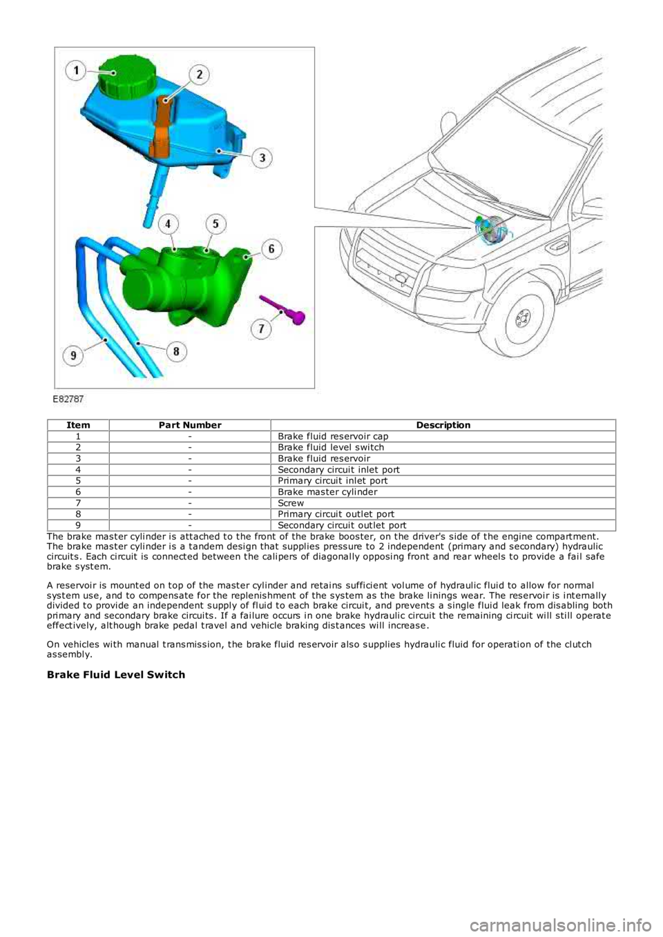
ItemPart NumberDescription
1-Brake fluid res ervoir cap2-Brake fluid level s wi tch
3-Brake fluid res ervoir
4-Secondary circui t inlet port5-Primary circui t inl et port
6-Brake mas ter cyli nder
7-Screw8-Primary circui t outl et port
9-Secondary circui t out let port
The brake mas t er cyli nder i s att ached t o t he front of the brake boos ter, on t he driver's s ide of t he engine compart ment.The brake mas t er cyli nder i s a t andem desi gn that s uppl ies press ure to 2 independent (primary and s econdary) hydrauliccircuit s . Each ci rcuit is connect ed between t he cali pers of diagonal ly opposi ng front and rear wheel s t o provide a fai l safebrake s yst em.
A reservoi r is mount ed on t op of the mast er cyl inder and retai ns suffi ci ent vol ume of hydraul ic flui d to allow for normals ys t em us e, and to compens ate for the replenis hment of the s ys tem as the brake li nings wear. The res ervoi r is i nt ernall ydivided t o provi de an independent s uppl y of fl ui d t o each brake circui t, and prevents a s ingle flui d leak from dis abling bot hpri mary and secondary brake circui ts . If a fai lure occurs i n one brake hydrauli c circui t the remaining ci rcuit wi ll s ti ll operat eeffect ively, alt hough brake pedal t ravel and vehicle braking dis t ances wi ll increas e.
On vehicles wi th manual t rans mis s ion, t he brake fluid res ervoir als o s upplies hydrauli c fluid for operati on of the cl ut chas sembl y.
Brake Fluid Level Switch
Page 472 of 3229
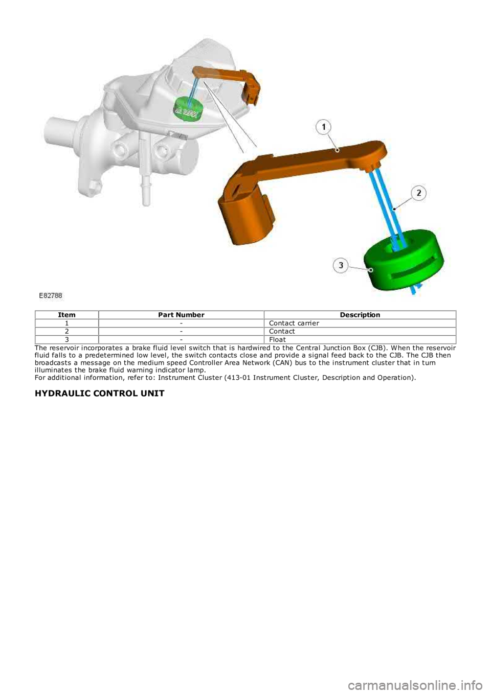
ItemPart NumberDescription
1-Contact carri er2-Contact
3-Float
The res ervoir i ncorporates a brake fl uid l evel s wit ch t hat i s hardwired t o t he Cent ral Junct ion Box (CJB). W hen t he res ervoirfl uid fall s to a predet ermi ned low l evel , the s wi tch contacts cl os e and provi de a s ignal feed back t o the CJB. The CJB t henbroadcas t s a mes s age on t he medium speed Controll er Area Network (CAN) bus t o t he i ns t rument clus ter t hat i n t urnil lumi nat es t he brake fluid warning i ndi cat or lamp.For addit ional informat ion, refer t o: Ins t rument Clus ter (413-01 Inst rument Cl us t er, Des cript ion and Operat ion).
HYDRAULIC CONTROL UNIT
Page 473 of 3229
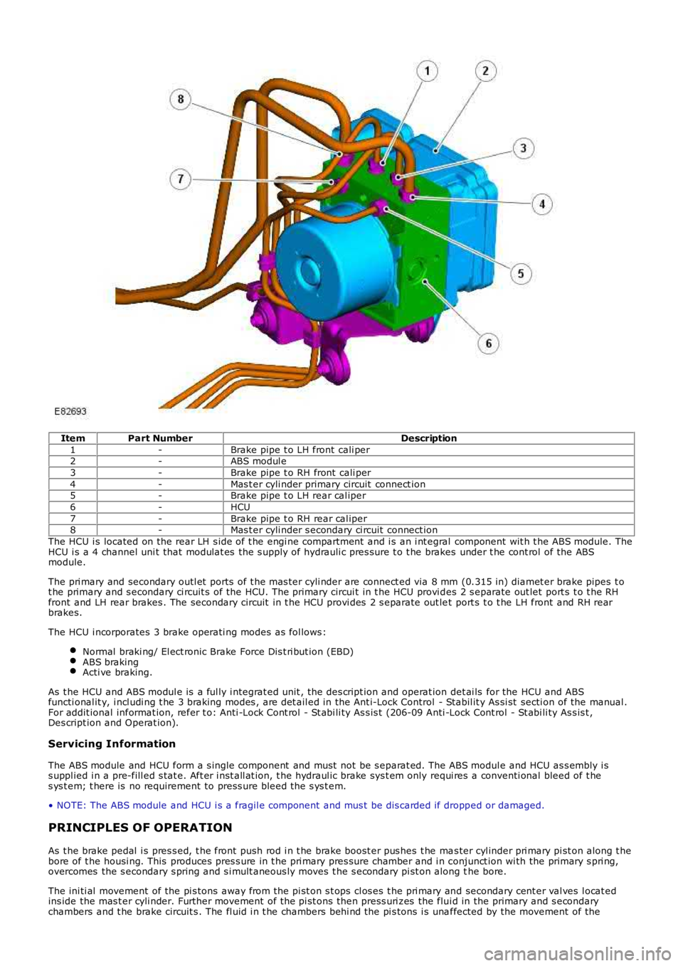
ItemPart NumberDescription
1-Brake pipe t o LH front cali per2-ABS modul e
3-Brake pipe t o RH front cali per
4-Mas t er cyli nder primary circuit connect ion5-Brake pipe t o LH rear cal iper
6-HCU
7-Brake pipe t o RH rear cal iper8-Mas t er cyli nder s econdary ci rcuit connect ion
The HCU i s located on the rear LH s ide of t he engi ne compartment and i s an i nt egral component wit h t he ABS module. TheHCU i s a 4 channel uni t that modulat es the s upply of hydrauli c pres sure t o t he brakes under t he cont rol of the ABSmodule.
The pri mary and secondary outl et ports of t he mas ter cyli nder are connect ed via 8 mm (0.315 in) diamet er brake pipes t ot he primary and s econdary ci rcuit s of the HCU. The primary circui t in t he HCU provi des 2 s eparate out let port s t o t he RHfront and LH rear brakes . The secondary circuit in t he HCU provi des 2 s eparate out let port s t o t he LH front and RH rearbrakes.
The HCU i ncorporates 3 brake operati ng modes as fol lows :
Normal braki ng/ El ect ronic Brake Force Dis t ri but ion (EBD)ABS brakingActi ve braking.
As t he HCU and ABS modul e is a ful ly i ntegrat ed unit , the des cript ion and operat ion det ai ls for the HCU and ABSfuncti onal it y, i ncl udi ng t he 3 braking modes , are det ail ed in the Ant i-Lock Control - Stabil it y As si st secti on of the manual .For addit ional informat ion, refer t o: Anti -Lock Cont rol - St abi li ty As s is t (206-09 Anti -Lock Cont rol - St abi li ty As s is t ,Des cript ion and Operat ion).
Servicing Information
The ABS module and HCU form a s ingle component and must not be s eparat ed. The ABS modul e and HCU as s embly i ss uppl ied i n a pre-fill ed s tat e. Aft er i nst all at ion, t he hydraul ic brake sys t em only requi res a conventi onal bleed of t hes ys t em; t here is no requirement to press ure bleed t he s ys t em.
• NOTE: The ABS module and HCU i s a fragil e component and mus t be dis carded if dropped or damaged.
PRINCIPLES OF OPERATION
As t he brake pedal i s pres s ed, t he front push rod i n t he brake boost er pus hes t he mas ter cyl inder pri mary pi st on along t hebore of t he housi ng. This produces pres s ure in t he pri mary pres sure chamber and i n conjunct ion wi th the primary s pri ng,overcomes the s econdary s pring and s i mult aneous ly moves t he s econdary pi st on along the bore.
The ini ti al movement of the pi s tons away from the pi st on s t ops cl os es t he pri mary and secondary cent er val ves l ocat edins ide the mas t er cyli nder. Further movement of the pi st ons then press uri zes the flui d in the primary and s econdarychambers and t he brake circuit s . The fl uid i n t he chambers behi nd the pi s tons i s unaffected by the movement of the
Page 474 of 3229

pis t ons and will flow unrest ri cted t hrough t he inlet ports , between t he chambers and t he res ervoir.
Pres s urized fluid ent ers the HCU that i s mounted on t he front of the ABS modul e. The HCU t hen modul ates t he s uppl y ofpres s urized fluid to the brakes under cont rol of the ABS modul e.For addit ional informat ion, refer t o: Anti -Lock Cont rol - St abi li ty As s is t (206-09 Anti -Lock Cont rol - St abi li ty As s is t ,Des cript ion and Operat ion).
Page 475 of 3229
Publi s hed: 11-May-2011
Hydraulic Brake Actuation - Hydraulic Brake Actuation
Diagnosi s and Tes ti ng
For addit ional informat ion.
REFER to: Brake Sys tem (206-00 Brake Sys tem - General Informati on, Diagnos is and Tes t ing).
Page 476 of 3229
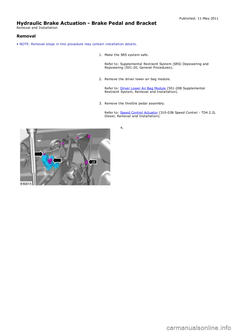
Publi s hed: 11-May-2011
Hydraulic Brake Actuation - Brake Pedal and Bracket
Removal and Inst all ati on
Removal
• NOTE: Removal s t eps in t his procedure may cont ain i nst all ati on det ail s.
Make t he SRS s ys t em s afe.
Refer t o: Supplement al Res t raint Sys tem (SRS) Depowering andRepowering (501-20, General Procedures ).
1.
Remove t he dri ver l ower ai r bag modul e.
Refer t o: Dri ver Lower Air Bag Module (501-20B SupplementalRes traint Sys t em, Removal and Inst all at ion).
2.
Remove t he thrott le pedal ass embly.
Refer t o: Speed Cont rol Act uator (310-03B Speed Cont rol - TD4 2.2LDi es el, Removal and Ins tal lat ion).
3.
4.
Page 477 of 3229
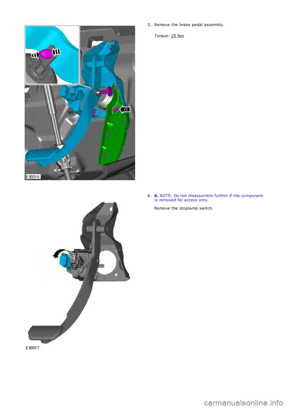
Remove t he brake pedal as s embly.
T orque: 25 Nm 5.
6.
NOTE: Do not dis ass embl e further if t he component
i s removed for acces s onl y.
Remove t he s toplamp swi tch.
6.
Page 478 of 3229
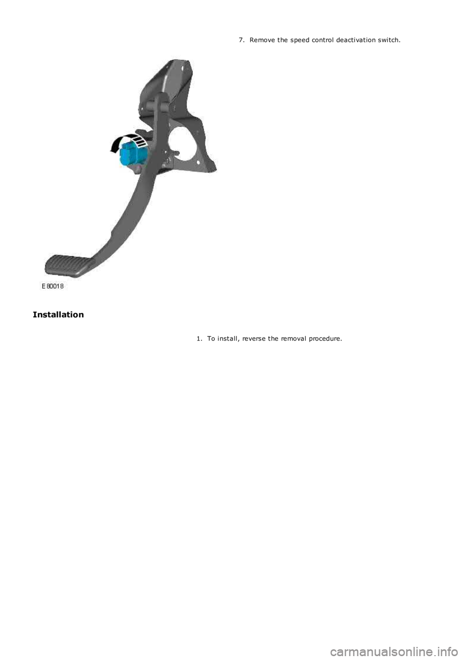
Remove t he s peed control deacti vat ion s wi tch.7.
Installation
To i nst all , revers e t he removal procedure.1.
Page 479 of 3229
Publi s hed: 11-May-2011
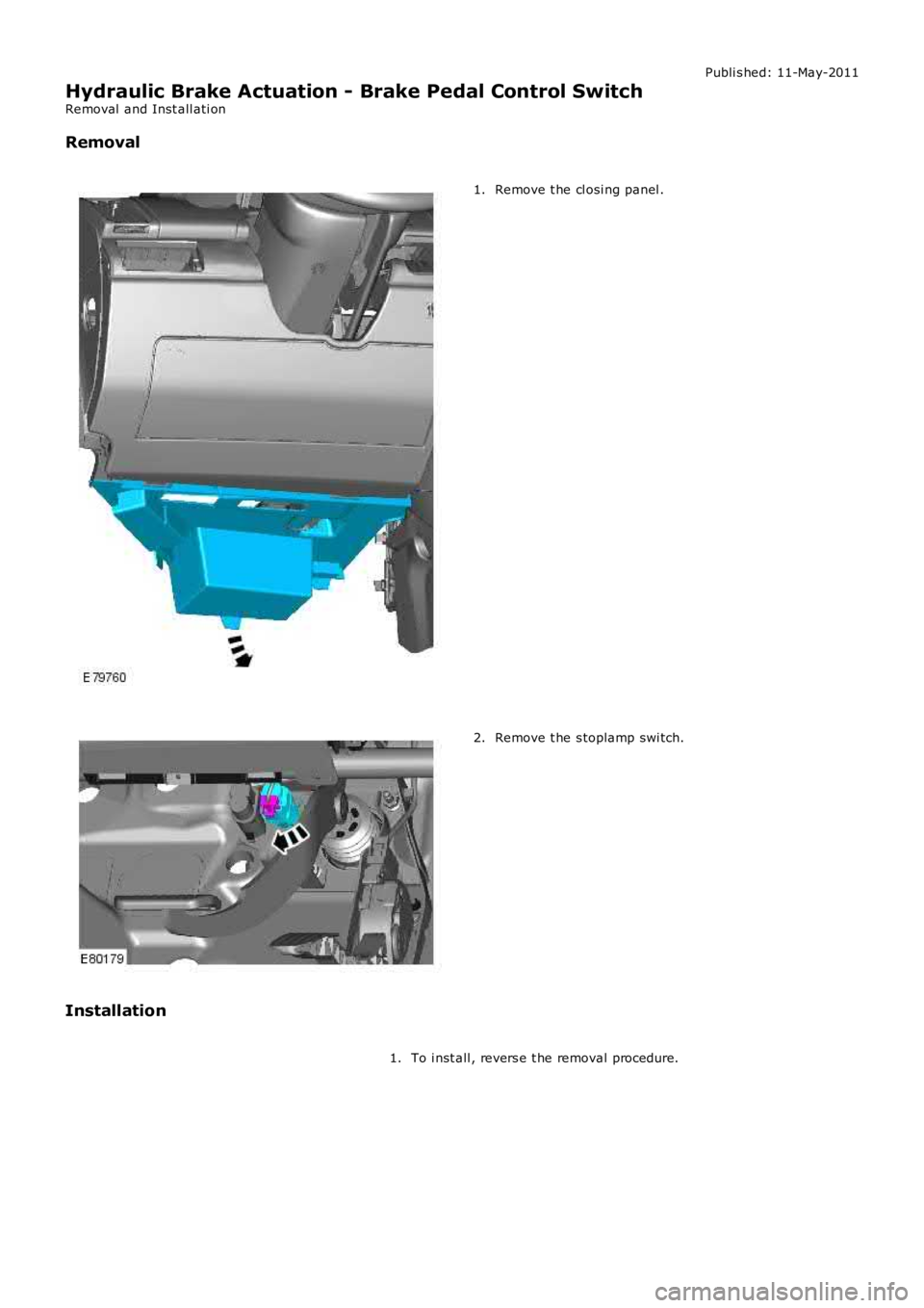
Hydraulic Brake Actuation - Brake Pedal Control Switch
Removal and Inst all ati on
Removal
Remove t he cl osi ng panel .1.
Remove t he s toplamp swi tch.2.
Installation
To i nst all , revers e t he removal procedure.1.
Page 480 of 3229
Publi s hed: 11-May-2011
Hydraulic Brake Actuation - Brake Master Cylinder
Removal and Inst all ati on
Removal
• CAUTIO NS: Extreme cleanli nes s mus t be exercis ed when handli ng thes e component s.
If brake fluid is s pil t on the pai ntwork, t he affect ed area must be immedi ately was
hed down wi th col d wat er.
• NOTE: Removal s t eps in t his procedure may cont ain i nst all ati on det ail s.
All vehicles
1. W ARNING: Make sure t o s upport the vehicle wit h axle
s tands .
Rais e and s upport t he vehi cl e.
1.
Remove t he brake fluid res ervoir.
Refer t o: Brake Fluid Reservoi r (206-06 Hydraul ic Brake Act uat ion,
Removal and Ins tall ati on).
2.
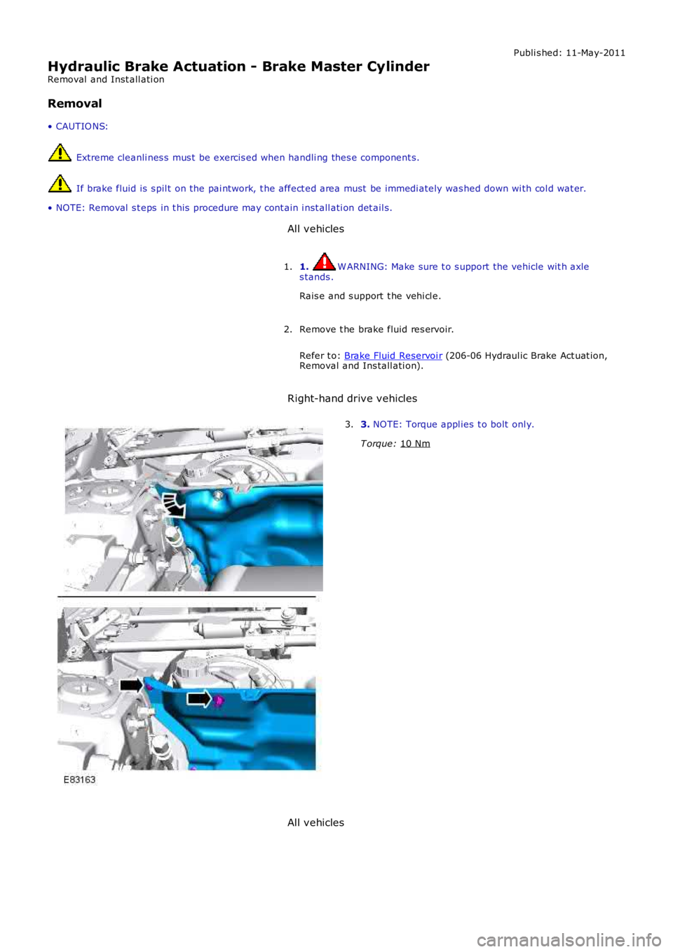
Right-hand drive vehicles 3.
NOTE: Torque appl ies t o bolt onl y.
T orque: 10 Nm 3.
All vehicles