LAND ROVER FRELANDER 2 2006 Repair Manual
FRELANDER 2 2006
LAND ROVER
LAND ROVER
https://www.carmanualsonline.info/img/64/57251/w960_57251-0.png
LAND ROVER FRELANDER 2 2006 Repair Manual
Trending: cruise control, boot, check oil, heater, oil capacities, transmission fluid, ad blue
Page 501 of 3229
1W i th firm pres sure s ti ll held on the brake pedal, s t art t he engi ne.
Did t he pedal t ravel increas e as t he engi ne s tarted?YesThe vacuum funct ion of t he brake boost er is operat ing normall y. Check for DTCs i ndi cat ing a faultels ewhere i n the sys tem.NoCHECK the vacuum circui t to the brake boos t er.
Page 502 of 3229
Publi s hed: 11-May-2011
Anti-Lock Control - Anti-Lock Brake System (ABS) Module
Removal and Inst all ati on
Removal
• CAUTIO NS:
Extreme cleanli nes s mus t be exercis ed when handli ng thes e component s.
If brake fluid is s pil t on the pai ntwork, t he affect ed area must be immedi ately washed down wi th col d wat er.
All vehicles
1. W ARNING: Make sure t o s upport the vehicle wit h axles tands .
Rais e and s upport t he vehi cl e.
1.
Di sconnect t he bat t ery ground cable.
Refer t o: Specificati ons (414-00 Bat tery and Charging Sys tem -General Informat ion, Specificati ons).
2.
Remove t he bat t ery t ray.
Refer t o: Bat t ery Tray (414-01 Bat tery, Mount ing and Cables ,Removal and Ins tall ati on).
3.
Right-hand drive vehicles
Remove t he plenum chamber panel.4.
Left-hand drive vehicles
Remove t he winds hield wiper motor and l inkage.
Refer t o: W i nds hield W i per Mot or (501-16 W ipers and W as hers ,Removal and Ins tall ati on).
5.
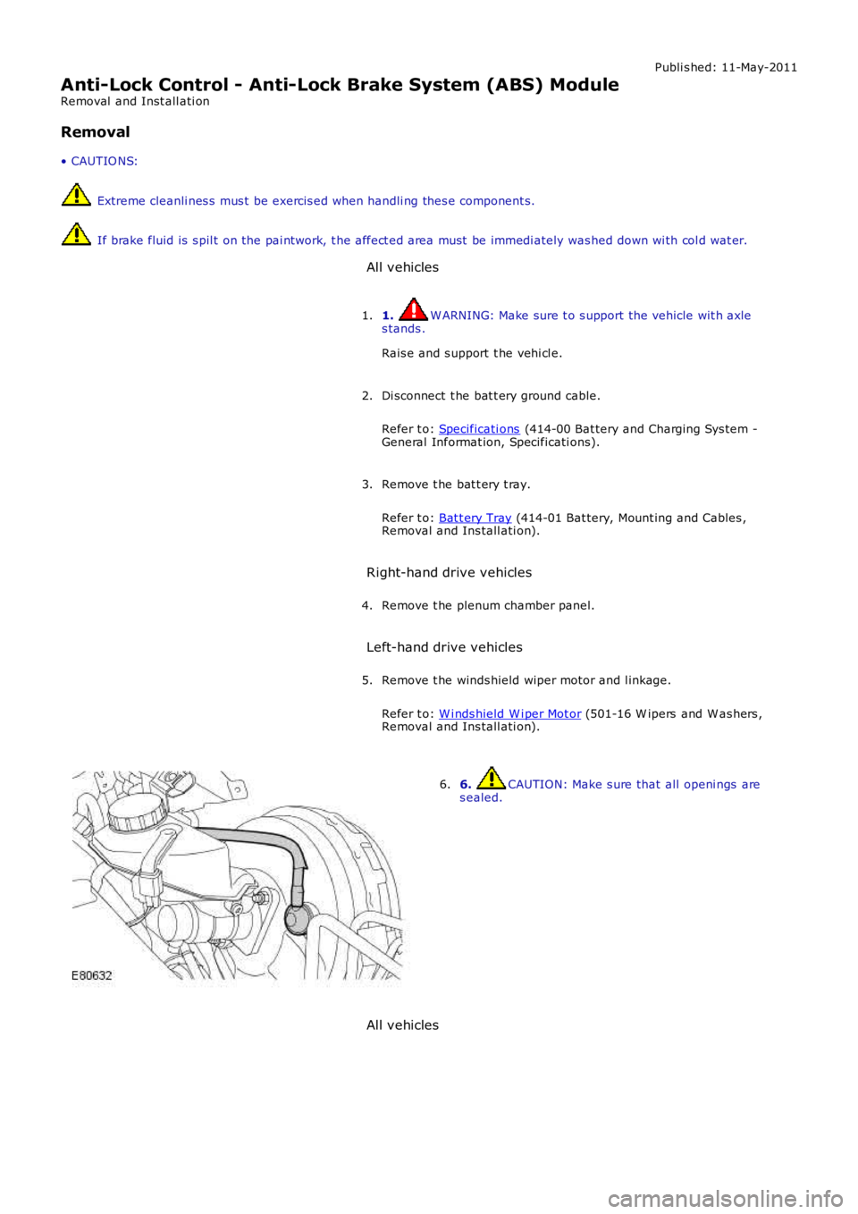
6. CAUTION: Make s ure that all openi ngs ares ealed.6.
All vehicles
Page 503 of 3229
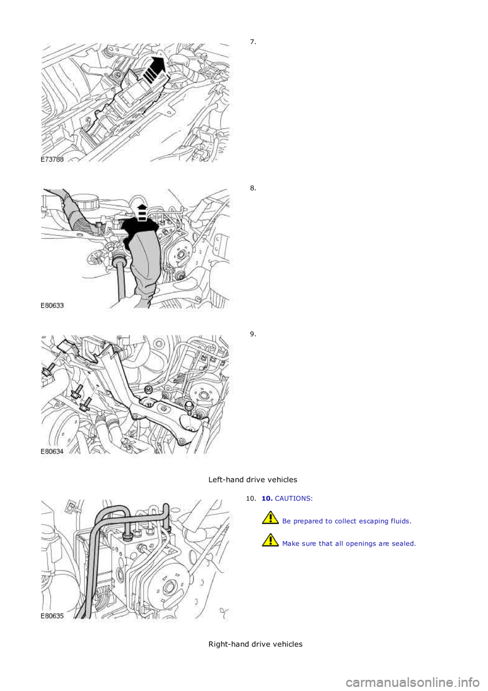
7.
8.
9.
Left-hand drive vehicles
10. CAUTIONS:
Be prepared t o collect es caping flui ds .
Make s ure that all openings are sealed.
10.
Right-hand drive vehicles
Page 504 of 3229
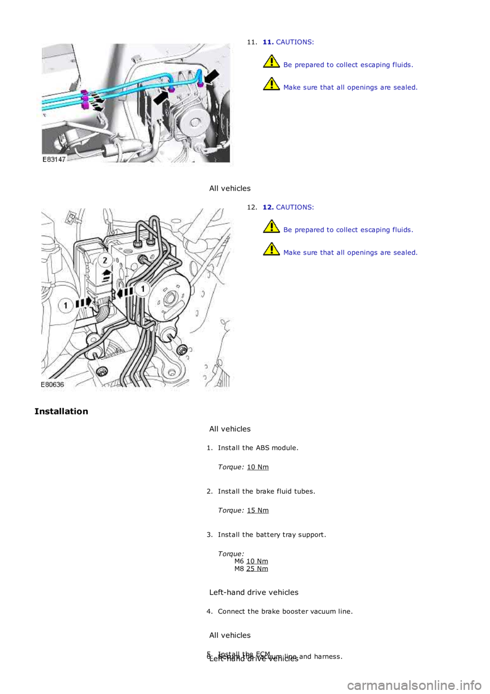
11.
CAUTIONS: Be prepared t o collect es caping flui ds .
Make s ure that all openings are sealed.
11.
All vehicles 12.
CAUTIONS: Be prepared t o collect es caping flui ds .
Make s ure that all openings are sealed.
12.
Installation All vehicles
Inst all t he ABS module.
T orque: 10 Nm 1.
Inst all t he brake fluid tubes.
T orque: 15 Nm 2.
Inst all t he bat t ery t ray s upport .
T orque: M6 10 Nm M8
25 Nm 3.
Left-hand drive vehicles Connect t he brake boost er vacuum l ine.
4.
All vehicles Inst all t he ECM.
5.
Secure t he vacuum line and harnes s .
6.
Left-hand drive vehicles
Page 505 of 3229
Inst all t he winds hield wiper motor and l inkage.
Refer t o: W i nds hield W i per Mot or (501-16 W ipers and W as hers ,Removal and Ins tall ati on).
7.
Right-hand drive vehicles
Inst all t he plenum chamber panel.8.
All vehicles
Inst all t he bat t ery t ray.
Refer t o: Bat t ery Tray (414-01 Bat tery, Mount ing and Cables ,Removal and Ins tall ati on).
9.
Connect t he batt ery ground cable.
Refer t o: Specificati ons (414-00 Bat tery and Charging Sys tem -General Informat ion, Specificati ons).
10.
Bleed t he brake s ys tem.
Refer t o: Brake Syst em Bl eedi ng (206-00 Brake Syst em - GeneralInformat ion, General Procedures).
11.
If a new component has been ins t al led, configure usi ng Land Roverapproved diagnos t ic equipment .12.
Page 506 of 3229
Publi s hed: 11-May-2011
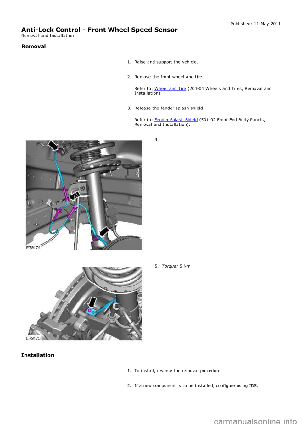
Anti-Lock Control - Front Wheel Speed Sensor
Removal and Inst all ati on
Removal
Rais e and s upport t he vehi cl e.
1.
Remove t he front wheel and t ire.
Refer t o: W heel and Ti re (204-04 W heel s and Tires, Removal and
Inst all at ion).
2.
Releas e t he fender spl as h shi el d.
Refer t o: Fender Spl ash Shi eld (501-02 Front End Body Panel s ,
Removal and Ins tall ati on).
3. 4.
T orque:
5 Nm 5.
Installation To i nst all , revers e t he removal procedure.
1.
If a new component i s t o be ins t al led, configure usi ng IDS.
2.
Page 507 of 3229
Publi s hed: 11-May-2011
Anti-Lock Control - Rear Wheel Speed Sensor
Removal and Inst all ati on
Removal
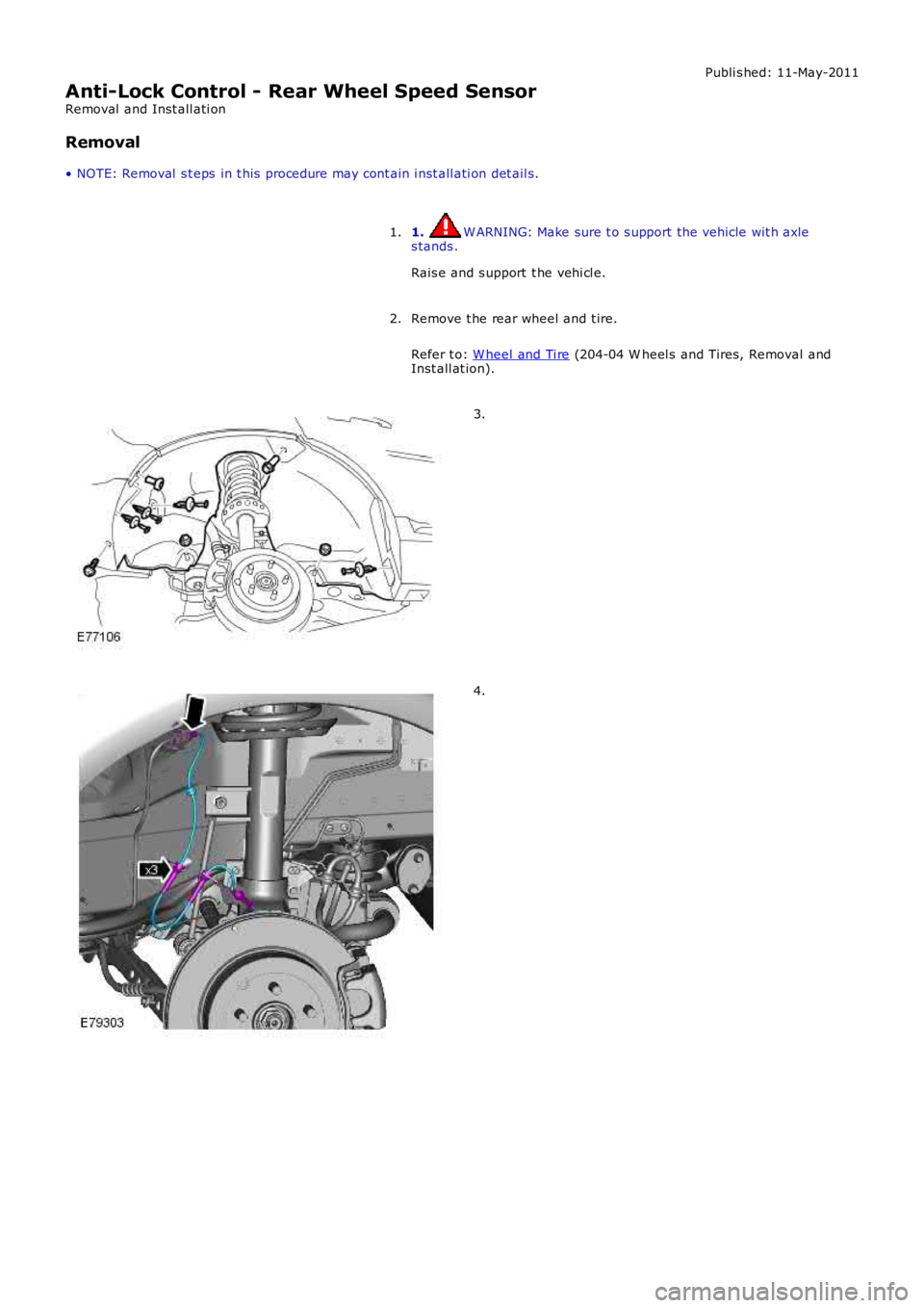
• NOTE: Removal s t eps in t his procedure may cont ain i nst all ati on det ail s.
1. W ARNING: Make sure t o s upport the vehicle wit h axles tands .
Rais e and s upport t he vehi cl e.
1.
Remove t he rear wheel and t ire.
Refer t o: W heel and Ti re (204-04 W heel s and Tires, Removal andInst all at ion).
2.
3.
4.
Page 508 of 3229
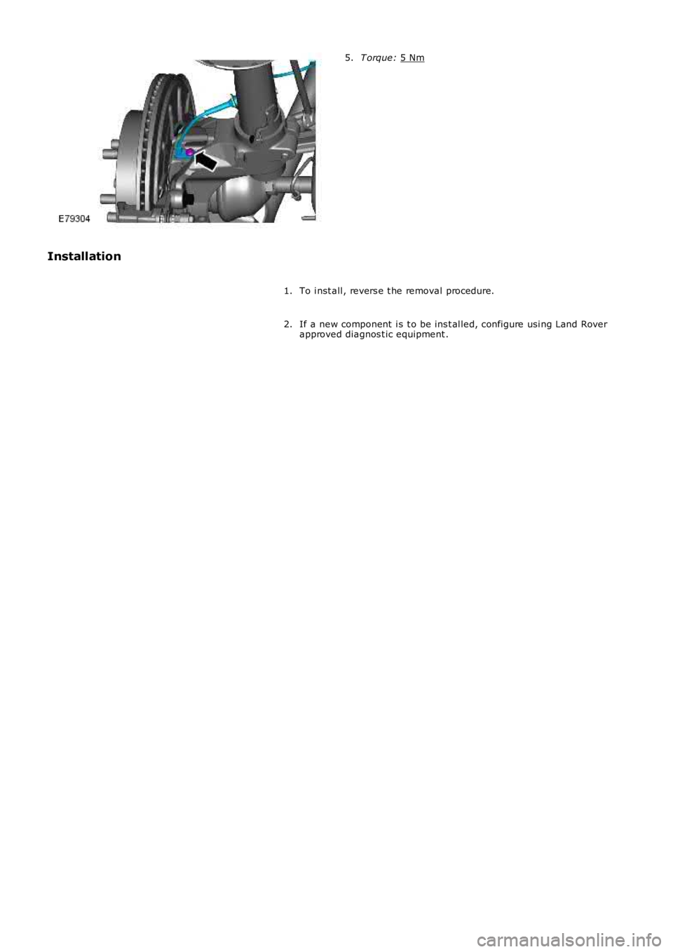
T orque:
5 Nm 5.
Installation To i nst all , revers e t he removal procedure.
1.
If a new component i s t o be ins t al led, configure usi ng Land Rover
approved diagnos t ic equipment .
2.
Page 509 of 3229
Publi s hed: 11-May-2011
Anti-Lock Control - Traction Control - Anti-Lock Control - Traction Control
Des cript ion and Operat ion
OVERVIEW
The anti -l ock control - tract ion control secti on is incorporated wit hin t he anti -l oc k control - st abil it y ass i st s ecti on of the
works hop manual .
For addit ional informat ion, refer t o: Anti -Lock Cont rol - St abi li ty As s is t (206-09C Anti -Lock Cont rol - St abi lit y As s is t,
Des cript ion and Operat ion).
Page 510 of 3229
Publi s hed: 11-May-2011
Anti-Lock Control - Stability Assist - Anti-Lock Control - Stability Assist
Des cript ion and Operat ion
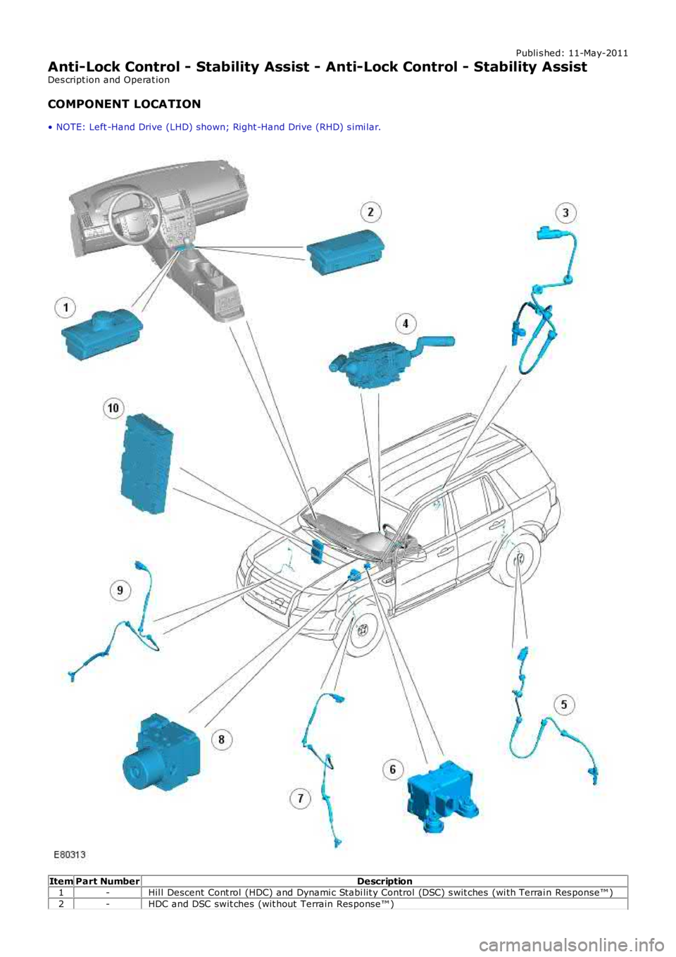
COMPONENT LOCATION
• NOTE: Left -Hand Drive (LHD) shown; Right -Hand Drive (RHD) s imi lar.
ItemPart NumberDescription1-Hil l Descent Cont rol (HDC) and Dynami c Stabi lit y Control (DSC) s wit ches (wi th Terrain Res ponse™ )
2-HDC and DSC swit ches (wit hout Terrain Res ponse™ )
Trending: horn, driver seat adjustment, air filter, fuel type, light, bulb, overheating
