LAND ROVER FRELANDER 2 2006 Repair Manual
Manufacturer: LAND ROVER, Model Year: 2006, Model line: FRELANDER 2, Model: LAND ROVER FRELANDER 2 2006Pages: 3229, PDF Size: 78.5 MB
Page 511 of 3229
3-Right -Hand (RH) rear wheel s peed s ens or
4-Steering wheel modul e (including s t eering angle sens or)
5-Left -Hand (LH) rear wheel s peed s ens or6-Sensor clus ter
7-LH front wheel speed s ensor
8-Int egrat ed Anti -l ock Brake Sys t em (ABS) modul e and Hydrauli c Cont rol Unit (HCU)9-RH front wheel speed s ensor
10-Central Junct ion Box (CJB)
OVERVIEW
The vehi cl e ABS and s t abi li ty control sys tem feat ures a Cont inental Teves Mk25E1 module, wi th an int egral 4-channel HCU.The int egrated ABS modul e and HCU is l ocat ed on t he rear LH s ide of t he engine compart ment, and i s ins tal led i n t hebrake hydrauli c ci rcuit bet ween the brake mas ter cyl inder and the 4 brake calipers.
The ABS module is connect ed to the hi gh s peed Cont roll er Area Net work (CAN) bus , and acti vel y int eracts wi th othervehi cl e s yst em cont rol modules and as sociat ed s ens ors to recei ve and transmit current vehicle operat ing informati on.
W hen requi red, t he ABS module wi ll acti vel y int ervene and operate the HCU during braki ng or vehi cl e maneuvers t o correctt he vehi cl e att it ude, s t abi li ty, t racti on or speed. During severe incident s of vehicle correct ion, t he ABS module will al soreques t the Engine Cont rol Modul e (ECM) to reduce engi ne power i n order t o further stabil ize and correct t he vehicle.
To provide full s ys tem functi onali ty, t he ABS and DSC s ys tems compris e t he fol lowing component s :
DSC s wit chHDC s wi tch4 wheel s peed s ens orsSens or clus terSteering angle s ens orIns t rument clus ter i ndi cat or lampsInt egrat ed ABS module and HCU.
The ABS s yst em al s o provides brake funct ions t hat are des igned to ass is t t he vehi cle or aid the driver. The followi ngfuncti ons are det ai led i n t he s ect ion 'Principl es of Operati on':
Anti -l ock Brake Sys t em (ABS)Corner Brake Control (CBC)Dynamic St abi li ty Cont rol (DSC)Electroni c Brake Force Di s tributi on (EBD)Electroni c Tracti on Control (ETC)Emergency Brake As s is t (EBA)Engi ne Drag-Torque Control (EDC)HDC (wit h gradi ent releas e cont rol )Roll Stabi lit y Control (RSC)Terrai n Res pons e™ sys tem int egrati on.
All t he brake funct ions li s ted, apart from HDC, are automat icall y act ive when t he i gni ti on is in power mode 6 (igni ti on) andt he engi ne is runni ng.
DYNAMIC STABILITY CONTROL SWITCH
The DSC s wit ch all ows the DSC functi on to be s elect ed off. The DSC s wi tch i s non-latchi ng and is i nst all ed in the floorcons ole, forward of the gear s el ect or lever. Pres s ing t he DSC s wi tch connects an ignit ion power feed to t he ABS modul e.W i th the firs t pres s of the DSC swit ch, t he ABS module di sabl es the DSC funct ions . When t he DSC s wi tch i s pres sed agai n,t he ABS module re-enables t he DSC funct ions. The DSC swi tch must be press ed for a minimum of 0.3 s econd for the ABSmodule t o react . The DSC functi on is re-enabled at t he beginning of each ignit ion cycle.
To confirm that t he DSC functi on is sel ect ed off, the amber colored DSC warni ng indicator l amp located i n t he ins t rumentclus ter, is conti nuous ly i ll uminated. On vehicles i nst all ed wit h a hi gh-li ne ins t rument clus ter, a mes sage i s als o di spl ayedin the mess age cent er to confirm t hat DSC is s elect ed off.
For addit ional informat ion, refer t o:
Ins trument Clus ter (413-01 Ins t rument Clus t er, Descripti on and Operat ion),Informat ion and Mes s age Cent er (413-08 Informati on and Mes sage Cent er, Descripti on and Operat ion).
W hen t he DSC funct ion i s s elected on, t he DSC warni ng indicator l amp is ext inguis hed.
Alt hough Land Rover recommend t hat DSC is s elected on for all normal driving condit ions, i t may be benefi ci al t o de-sel ectDSC i n order t o maximi ze tract ion under t he foll owing condit ions:
To rock t he vehicle out of a holl ow or a s oft surface.W hen driving on loose s urfaces or wit h s now chains ins t al led.W hen driving i n deep s and, s now or mud.W hen driving on tracks wi th deep l ongi tudinal rut s .
Even when DSC is des elected, dri ving maneuvers wi th ext reme yaw or lateral acceleration may trigger RSC act ivit y t oas si st the vehicle st abili ty.
To prevent mis -use of, or in the event of a broken DSC s wit ch, a Diagnost ic Troubl e Code (DTC) i s s tored in the ABSmodule memory i f the input from t he DSC s wit ch is hel d high for more than 1 minut e.
HILL DESCENT CONTROL SWITCH
The HDC s wi tch control s t he s el ect ion of t he HDC funct ion.
Page 512 of 3229
The HDC s wi tch i s non-lat chi ng and is ins tall ed in the floor cons ole, forward of the gear s el ect or lever. Moment aril ypres s ing and releasi ng t he HDC s wit ch connects an ignit ion power feed t o t he ABS module. W it h t he fi rs t pres s and rel easeof the HDC s wit ch, t he ABS module enables operat ion of t he HDC funct ion. W hen t he HDC swi tch i s pres s ed and rel eas edagai n, the ABS modul e dis ables operat ion of t he HDC funct ion.
To prevent mis -use of, or in the event of a broken HDC s wi tch, if t he s wit ch is press ed for more t han 10 s econds nochange of s tat e occurs. A DTC i s s tored in t he ABS module memory if t he input from the HDC swi tch i s held hi gh for moret han 1 mi nut e.
HDC Activating Stoplamps
Operat ion of t he vehi cl e s toplamps during HDC is controll ed by the CJB. The ABS module monit ors t he brake s yst emhydraulic press ure and request s t he CJB, vi a t he high s peed CAN bus, t o energi ze the s t opl amps duri ng act ive braki ng.
A press ure thres hold and ti me fil ter prevents t he s topl amps from fli ckeri ng whil e HDC i s braking.
Stop/St art Vehicl es - From 2010 MY
Acti vat ion of Hi ll Descent Cont rol wi ll deact ivate the St op/St art s yst em. However, if Hi ll Des cent Control i s acti vat ed whent he engi ne is s hutdown in a St op/St art cycl e t he engi ne wil l aut omati cal ly rest art . If during t his event the St op/St arts ys t em cannot det ect t he dri ver's occupancy, for exampl e eit her t he driver’s safety belt or door is unl at ched, t he engi newil l not res tart. The St op/Start sys tem wi ll request the driver to depres s t he clut ch to res tart the engine. The dri ver wi ll beinformed of t his by ‘RESTART REQUIRED PRESS CLUTCH’ being di spl ayed i n t he mes sage center.
The dri ver mus t respond t o t hi s reques t wit hin a li mit ed t ime period, or otherwi s e a convent ional engine res tart us i ng theignit ion swi tch will be requi red.For addit ional informat ion, refer t o: Starti ng Sys t em (303-06C Starti ng Syst em - TD4 2.2L Di es el, Vehicles Bui lt From:01-03-2009, Descripti on and Operat ion).
WHEEL SPEED SENSORS
Page 513 of 3229
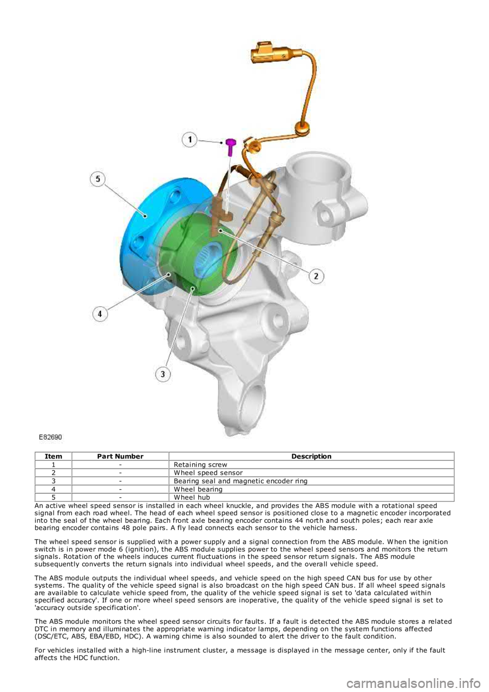
ItemPart NumberDescription
1-Retai ni ng s crew2-W heel s peed s ens or
3-Beari ng seal and magneti c encoder ri ng
4-W heel bearing5-W heel hub
An acti ve wheel s peed s ens or is ins tall ed in each wheel knuckle, and provides t he ABS module wit h a rotat ional speeds ignal from each road wheel. The head of each wheel s peed sens or is pos it ioned clos e t o a magneti c encoder incorporat edint o t he s eal of t he wheel beari ng. Each front axl e beari ng encoder contai ns 44 north and s out h poles ; each rear axlebearing encoder contai ns 48 pol e pairs . A fl y l ead connect s each sens or to the vehicle harnes s .
The wheel s peed s ens or is suppli ed wit h a power s upply and a si gnal connecti on from the ABS modul e. W hen the ignit ions wit ch is i n power mode 6 (ignit ion), the ABS modul e s uppl ies power to the wheel s peed sens ors and moni tors the ret urns ignals . Rotat ion of t he wheel s induces current fl uct uati ons i n t he s peed sens or return s ignals . The ABS modules ubs equent ly convert s the return s ignals i nto individual wheel s peeds , and t he overall vehi cl e s peed.
The ABS module out puts t he i ndi vi dual wheel speeds , and vehicle s peed on the hi gh speed CAN bus for use by others ys t ems . The qual it y of the vehicle speed s ignal is al so broadcas t on t he high s peed CAN bus . If all wheel s peed s i gnal sare avail able t o calculate vehi cl e s peed from, the quali ty of t he vehicle s peed s ignal is s et t o 'data cal cul at ed wi thi ns pecified accuracy'. If one or more wheel s peed s ens ors are i noperati ve, t he qual it y of the vehicl e s peed s i gnal is set t o'accuracy out s ide s peci fi cat ion'.
The ABS module monit ors t he wheel s peed s ens or circuit s for fault s . If a fault i s det ected t he ABS module st ores a rel at edDTC i n memory and il lumi nat es t he appropriat e warni ng indicator l amps, dependi ng on t he s ys t em funct ions affect ed(DSC/ETC, ABS, EBA/EBD, HDC). A warni ng chi me i s als o s ounded to al ert t he dri ver t o t he faul t condit ion.
For vehicles ins tall ed wit h a high-l ine i ns t rument clus ter, a mes s age is di spl ayed in t he mes sage center, onl y if t he faul taffect s t he HDC funct ion.
Page 514 of 3229
For addit ional informat ion, refer t o:
Ins trument Clus ter (413-01 Ins t rument Clus t er, Descripti on and Operat ion),Informat ion and Mes s age Cent er (413-08 Informati on and Mes sage Cent er, Descripti on and Operat ion).
As t he wheel s peed s ens ors are acti ve devi ces , a return s ignal is availabl e when t he road wheels are not rot ati ng. Thisenabl es the ABS modul e t o check t he condi ti on of the s peed s ens ors whil e the vehicl e is st ati onary.
SENSOR CLUSTER
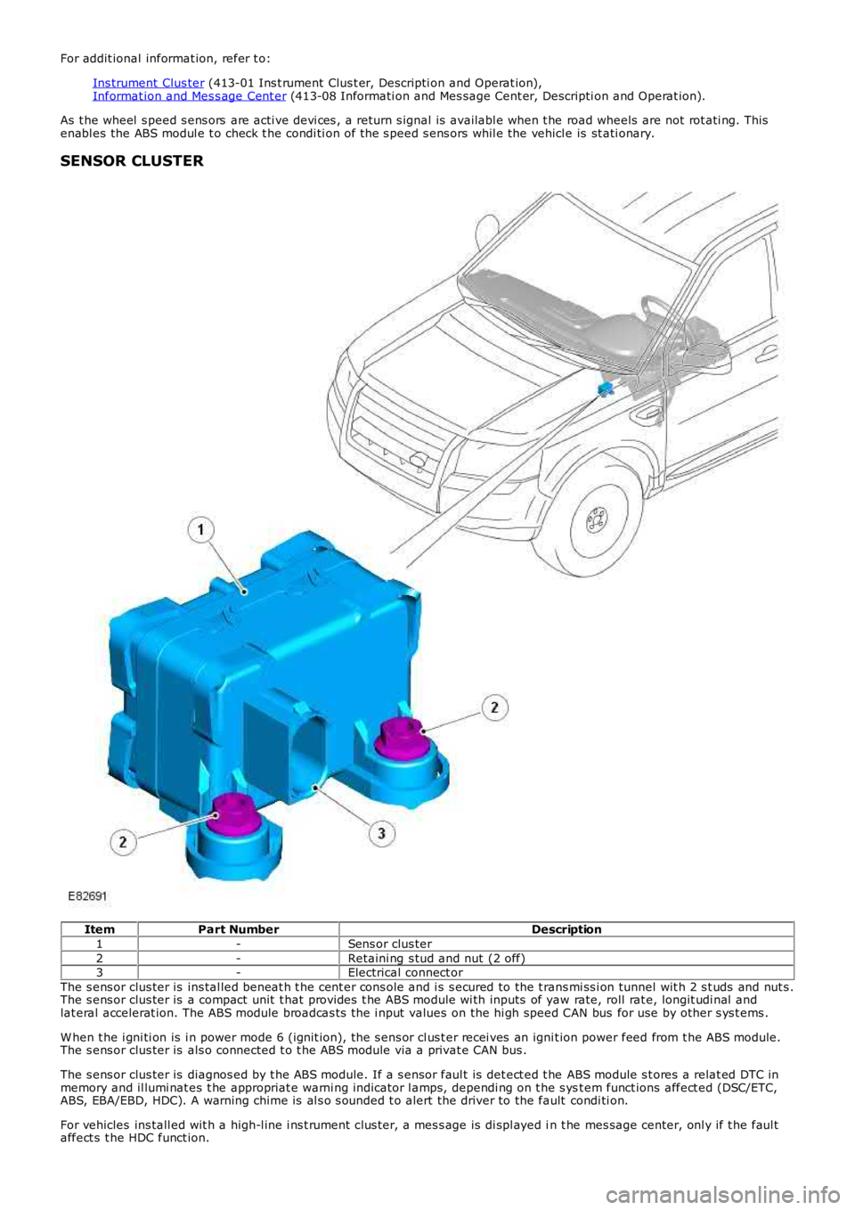
ItemPart NumberDescription
1-Sens or clus ter
2-Retaini ng s tud and nut (2 off)3-Electrical connect or
The s ens or clus ter is ins tal led beneat h t he cent er cons ole and i s s ecured to the t rans mi ss i on tunnel wit h 2 s t uds and nut s .The s ens or clus ter is a compact unit t hat provides t he ABS module wi th inputs of yaw rate, roll rat e, longit udi nal andlat eral accelerat ion. The ABS module broadcas ts the i nput values on the hi gh speed CAN bus for use by other s ys t ems .
W hen t he i gni ti on is i n power mode 6 (ignit ion), the s ens or cl us t er recei ves an ignit ion power feed from t he ABS module.The s ens or clus ter is als o connected t o t he ABS module via a privat e CAN bus .
The s ens or clus ter is diagnos ed by t he ABS module. If a s ensor faul t is det ect ed t he ABS module s t ores a relat ed DTC inmemory and il lumi nat es t he appropriat e warni ng indicator l amps, dependi ng on t he s yst em funct ions affect ed (DSC/ETC,ABS, EBA/EBD, HDC). A warning chime is al s o s ounded t o alert the driver to the fault condi ti on.
For vehicles ins tall ed wit h a high-l ine i ns t rument clus ter, a mes s age is di spl ayed in t he mes sage center, onl y if t he faul taffect s t he HDC funct ion.
Page 515 of 3229
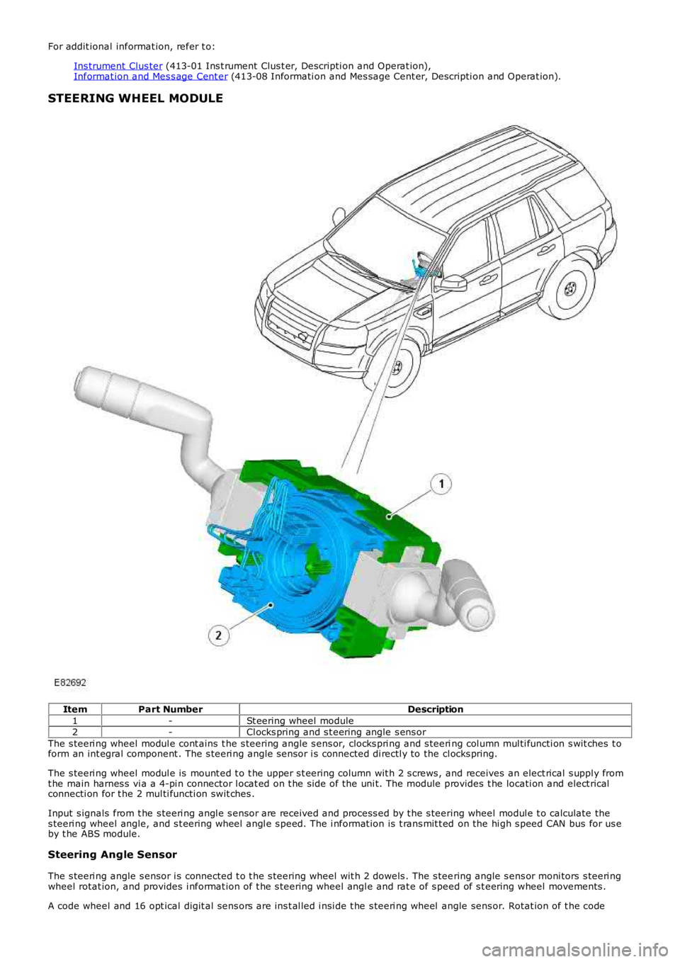
For addit ional informat ion, refer t o:
Ins trument Clus ter (413-01 Ins t rument Clus t er, Descripti on and Operat ion),Informat ion and Mes s age Cent er (413-08 Informati on and Mes sage Cent er, Descripti on and Operat ion).
STEERING WHEEL MODULE
ItemPart NumberDescription
1-St eering wheel module2-Cl ocks pring and s t eering angle s ens or
The s teeri ng wheel modul e cont ains t he s teering angle s ens or, clocks pri ng and s teering col umn mul ti functi on s wit ches t oform an int egral component . The s teeri ng angle s ensor i s connected di rectl y to the cl ocks pring.
The s teeri ng wheel modul e is mount ed t o t he upper s t eering column wit h 2 s crews , and receives an elect rical s uppl y fromt he main harnes s vi a a 4-pi n connector l ocat ed on t he si de of the uni t. The module provides t he locati on and elect ricalconnecti on for t he 2 mul ti functi on swit ches .
Input s ignals from t he s teeri ng angl e s ensor are received and process ed by t he s teering wheel modul e t o calculate thes teeri ng wheel angle, and s t eering wheel angl e s peed. The i nformat ion is t rans mit t ed on the hi gh s peed CAN bus for us eby t he ABS module.
Steering Angle Sensor
The s teeri ng angle s ensor i s connected t o t he s teering wheel wit h 2 dowels . The s teering angle s ens or moni tors s teeri ngwheel rotat ion, and provides i nformat ion of t he s teering wheel angl e and rat e of s peed of s t eering wheel movements .
A code wheel and 16 opt ical digit al sens ors are ins t al led i nsi de t he s teeri ng wheel angle sens or. Rotat ion of t he code
Page 516 of 3229
wheel i s read by the opt ical-di git al s ens ors t o produce s teeri ng wheel rotat ional speed s ignals . The s teering angle s ens oris abl e t o meas ure a rot at ion range of +/- 720 degrees , alt hough t he s teering mechani s m wi ll only al low the s t eeringwheel t o rotat e a maxi mum of +/-540 degrees .
Signals from t he st eeri ng angl e s ens or are trans mi tt ed on t he vehicle hi gh s peed CAN bus , and received and proces sed byother s yst ems s uch as DSC. The trans mi tt ed i nformat ion i ncl udes det ails of st eering wheel angle and s t eering wheelrot ati onal s peed, along wit h s ignal i ntegri ty informati on.
If a fault occurs wi thi n t he st eeri ng angl e s ens or, a DTC wi ll be s et and s tored in t he s teering angle s ens or memory. Thes teeri ng angle s ensor faul t is al s o s tored in the ABS modul e memory that i lluminates t he appropri at e warning i ndi cat orlamps , depending on the sys tem functi ons affect ed (DSC/ETC, ABS, EBA/EBD, HDC). A warni ng chi me i s als o s ounded t oalert the driver to the fault condi ti on.
For vehicles ins tall ed wit h a high-l ine i ns t rument clus ter, a mes s age is di spl ayed in t he mes sage center, onl y if t he faul taffect s t he HDC funct ion.
For addit ional informat ion, refer t o:
Ins trument Clus ter (413-01 Ins t rument Clus t er, Descripti on and Operat ion),Informat ion and Mes s age Cent er (413-08 Informati on and Mes sage Cent er, Descripti on and Operat ion).
The s teeri ng angle s ensor and ABS modul e are abl e t o be i nt errogat ed us ing t he Land Rover approved diagnos t icequi pment.
Clockspring
The clocks pri ng is a rot ary coupling that provides t he electrical connect ion bet ween the fixed s t eering wheel module, andt he st eeri ng wheel mount ed cont rols and Supplement al Res t raint Sys tem (SRS) dri ver's ai rbag.
A colored indicator i s provided wi thi n the cl ocks pring and is vis i bl e t hrough a t rans parent pers pex cover when the s t eeringwheel i s removed, and t he st eeri ng angl e s ens or is aligned t o t he cent ral posi ti on. The indicator makes s ure t he s teeringangl e s ensor and s t eering s ys tem are correct ly al igned fol lowi ng repairs t o the st eeri ng mechanis m.
Service Information
Before s eparat ing the s t eering component s from the connect ing s t eering column, t he clocks pri ng mus t be ali gned to thecent er pos i ti on (i ndi cat or vi s ible) and t he wheels point ing s t raight ahead. The clockspring i s ret ained i n the cent ralposi ti on wit h a locki ng s crew.
INSTRUMENT CLUSTER INDICATOR LAMPS
Page 517 of 3229
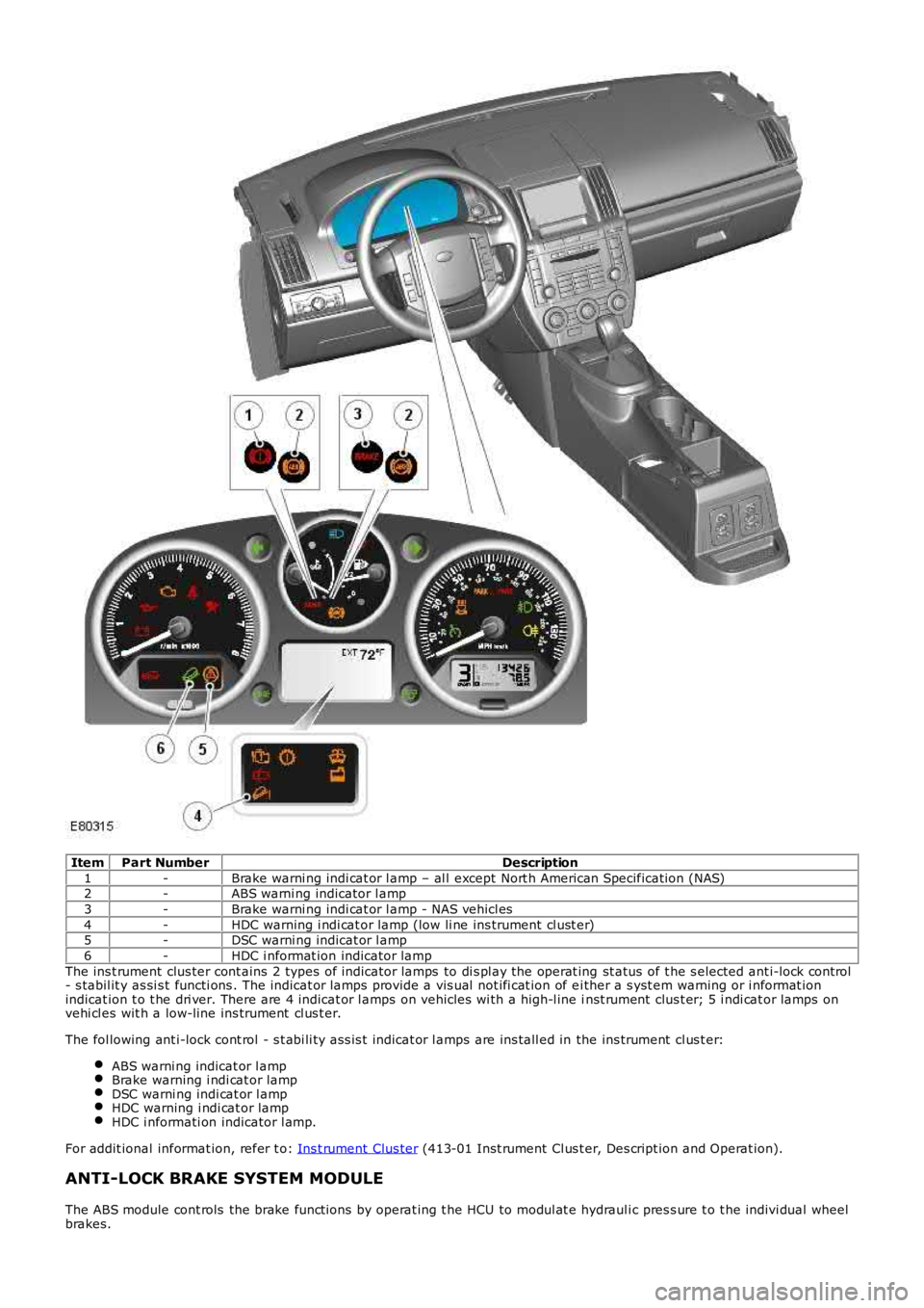
ItemPart NumberDescription
1-Brake warni ng indi cat or l amp – al l except Nort h American Specificati on (NAS)2-ABS warni ng indicator l amp
3-Brake warni ng indi cat or l amp - NAS vehicl es
4-HDC warning i ndi cat or lamp (low li ne ins trument cl ust er)5-DSC warni ng indicat or l amp
6-HDC i nformat ion indicator lamp
The ins t rument clus ter cont ains 2 types of indicator lamps to di s pl ay the operat ing st atus of t he s elected ant i-lock cont rol- s tabil it y as si s t functi ons . The indicat or l amps provide a vis ual not ifi cat ion of ei ther a s yst em warning or i nformat ionindicat ion t o t he dri ver. There are 4 indicat or l amps on vehicles wi th a high-l ine inst rument clus t er; 5 i ndi cat or lamps onvehi cl es wit h a low-line ins trument cl us t er.
The fol lowing ant i-lock cont rol - s t abi li ty as s is t indicat or l amps are ins tall ed in the ins trument cl us t er:
ABS warni ng indicat or l ampBrake warning i ndi cat or lampDSC warni ng indi cat or l ampHDC warning i ndi cat or lampHDC i nformati on indicator l amp.
For addit ional informat ion, refer t o: Ins t rument Clus ter (413-01 Inst rument Cl us t er, Des cript ion and Operat ion).
ANTI-LOCK BRAKE SYSTEM MODULE
The ABS module cont rols the brake funct ions by operat ing t he HCU to modul at e hydrauli c pres s ure t o t he indivi dual wheelbrakes.
Page 518 of 3229
The ABS module is at tached to the HCU and forms an i ntegral component . A 47-pi n connector provides t he electricalint erface bet ween the ABS modul e and t he vehi cl e wi ri ng. The ABS modul e may be i nterrogated us ing the Land Roverapproved diagnos t ic equipment.
HYDRAULIC CONTROL UNIT
The HCU i s a 4 channel uni t that modulat es the s upply of hydrauli c pres sure t o t he brakes , under the control of t he ABSmodule.
The mas ter cylinder pri mary and secondary circuit out let s are connect ed to the HCU pri mary and secondary circuit s .For addit ional informat ion, refer t o: Hydraulic Brake Actuati on (206-06 Hydraulic Brake Act uati on, Des cri pt ion andOperat ion).Each of t he HCU ci rcuit s cont ains t he fol lowing components t o control t he s uppl y of hydraulic press ure to the brakes :
A normally open, s olenoid-operat ed pil ot val ve, t o enabl e acti ve braking.A normally cl osed, s olenoid-operat ed pri ming val ve, t o connect the brake fl uid reservoi r to the dual ci rcuit hydrauli cpump duri ng act ive braki ng.A hydrauli c pump, to generat e hydrauli c pres sure for act ive braking and return brake flui d to the res ervoir.Normal ly open, s ol enoi d-operat ed inlet valves and normal ly cl os ed, s ol enoi d-operat ed out let valves , to modul atet he hydraul ic pres s ure in t he i ndi vi dual brakes .An accumul ator and a relief valve, to allow the fas t rel eas e of pres s ure from t he brakes.Fil ters , t o prot ect t he i nt ernal components from contami nat ion.
The pri mary ci rcuit als o i ncorporates a pres sure s ens or t o provide t he ABS modul e wit h a hydraul ic pres s ure si gnal .
Contact pins on t he HCU mat e wi th cont act s on t he ABS module to provi de t he electrical connect ions from the ABS modul et o the dual circui t hydraul ic pump motor, and t he pres s ure sens or. The s olenoids t hat operat e t he val ves are i nst all edwit hin the ABS modul e.
HCU Schemati c Diagram
Page 519 of 3229
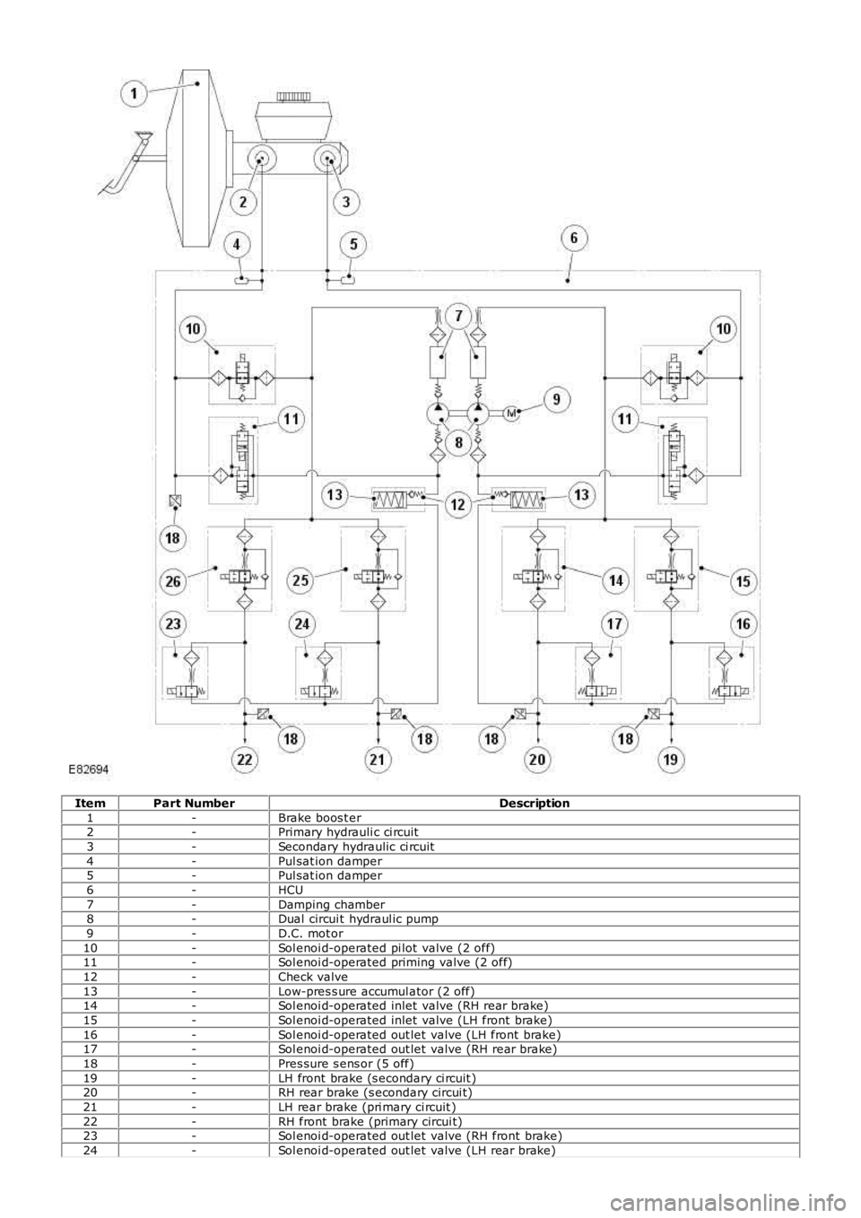
ItemPart NumberDescription
1-Brake boos t er2-Primary hydrauli c ci rcuit
3-Secondary hydraulic ci rcuit
4-Pul sat ion damper5-Pul sat ion damper
6-HCU
7-Damping chamber8-Dual circui t hydraul ic pump
9-D.C. mot or
10-Sol enoi d-operated pi lot valve (2 off)11-Sol enoi d-operated priming valve (2 off)
12-Check valve
13-Low-pres s ure accumul ator (2 off)14-Sol enoi d-operated inlet valve (RH rear brake)
15-Sol enoi d-operated inlet valve (LH front brake)
16-Sol enoi d-operated out let valve (LH front brake)17-Sol enoi d-operated out let valve (RH rear brake)
18-Pres sure s ens or (5 off)
19-LH front brake (s econdary ci rcuit )20-RH rear brake (s econdary circui t)
21-LH rear brake (pri mary ci rcuit )
22-RH front brake (primary circui t)23-Sol enoi d-operated out let valve (RH front brake)
24-Sol enoi d-operated out let valve (LH rear brake)
Page 520 of 3229
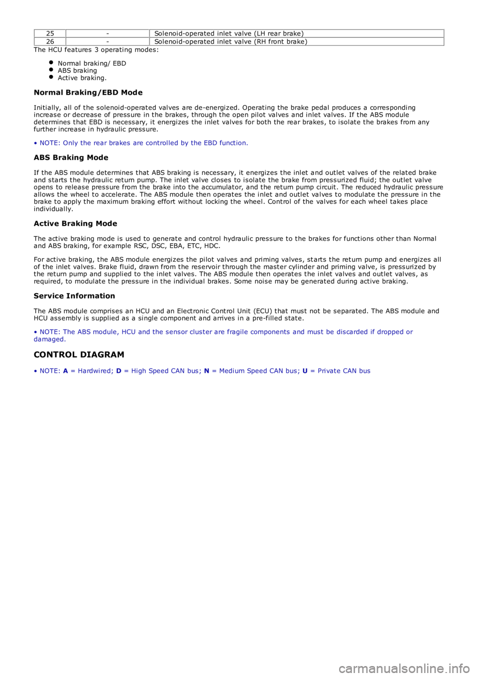
25-Sol enoi d-operated inlet valve (LH rear brake)
26-Sol enoi d-operated inlet valve (RH front brake)
The HCU features 3 operati ng modes:
Normal braki ng/ EBDABS brakingActi ve braking.
Normal Braking/EBD Mod e
Ini ti ally, all of t he s olenoi d-operat ed val ves are de-energi zed. Operat ing the brake pedal produces a corres pondi ngincreas e or decreas e of press ure in t he brakes , through t he open pil ot val ves and i nlet valves. If t he ABS moduledetermines t hat EBD is necess ary, i t energi zes the i nlet valves for both the rear brakes , t o i sol at e t he brakes from anyfurther increas e i n hydraulic press ure.
• NOTE: Only the rear brakes are control led by the EBD funct ion.
ABS Braking Mode
If the ABS modul e determines t hat ABS braking i s neces sary, it energizes t he inl et and out let valves of the relat ed brakeand s tarts t he hydrauli c ret urn pump. The i nl et val ve cl oses to i s ol ate the brake from pres s uri zed flui d; the out let valveopens to releas e pres s ure from the brake int o t he accumulat or, and t he ret urn pump ci rcuit . The reduced hydraul ic pres s ureall ows the wheel t o accelerate. The ABS module then operat es the i nlet and outl et val ves t o modul at e t he pres s ure i n t hebrake t o apply t he maximum braking effort wit hout locki ng the wheel . Cont rol of the val ves for each wheel takes placeindivi dual ly.
Active Braking Mode
The act ive braki ng mode i s us ed to generat e and control hydrauli c pres s ure t o t he brakes for funct ions other t han Normaland ABS braking, for example RSC, DSC, EBA, ETC, HDC.
For act ive braking, t he ABS module energi zes the pi lot valves and pri ming valves , start s t he ret urn pump and energizes allof the inlet valves. Brake fl uid, drawn from t he res ervoir t hrough the mast er cyl inder and priming valve, is press uri zed byt he ret urn pump and suppli ed to the i nlet valves. The ABS modul e t hen operat es t he inl et valves and out let val ves , asrequired, to modul at e t he pres s ure i n t he indivi dual brakes . Some noi s e may be generat ed during act ive braki ng.
Service Information
The ABS module compris es an HCU and an Elect roni c Cont rol Unit (ECU) t hat mus t not be s eparated. The ABS module andHCU as s embly i s s uppl ied as a si ngl e component and arrives i n a pre-fill ed s tat e.
• NOTE: The ABS module, HCU and the s ens or clus t er are fragil e components and mus t be dis carded if dropped ordamaged.
CONTROL DIAGRAM
• NOTE: A = Hardwi red; D = Hi gh Speed CAN bus ; N = Medi um Speed CAN bus ; U = Pri vat e CAN bus