LEXUS LS430 2003 Factory Repair Manual
Manufacturer: LEXUS, Model Year: 2003, Model line: LS430, Model: LEXUS LS430 2003Pages: 4500, PDF Size: 87.45 MB
Page 1591 of 4500
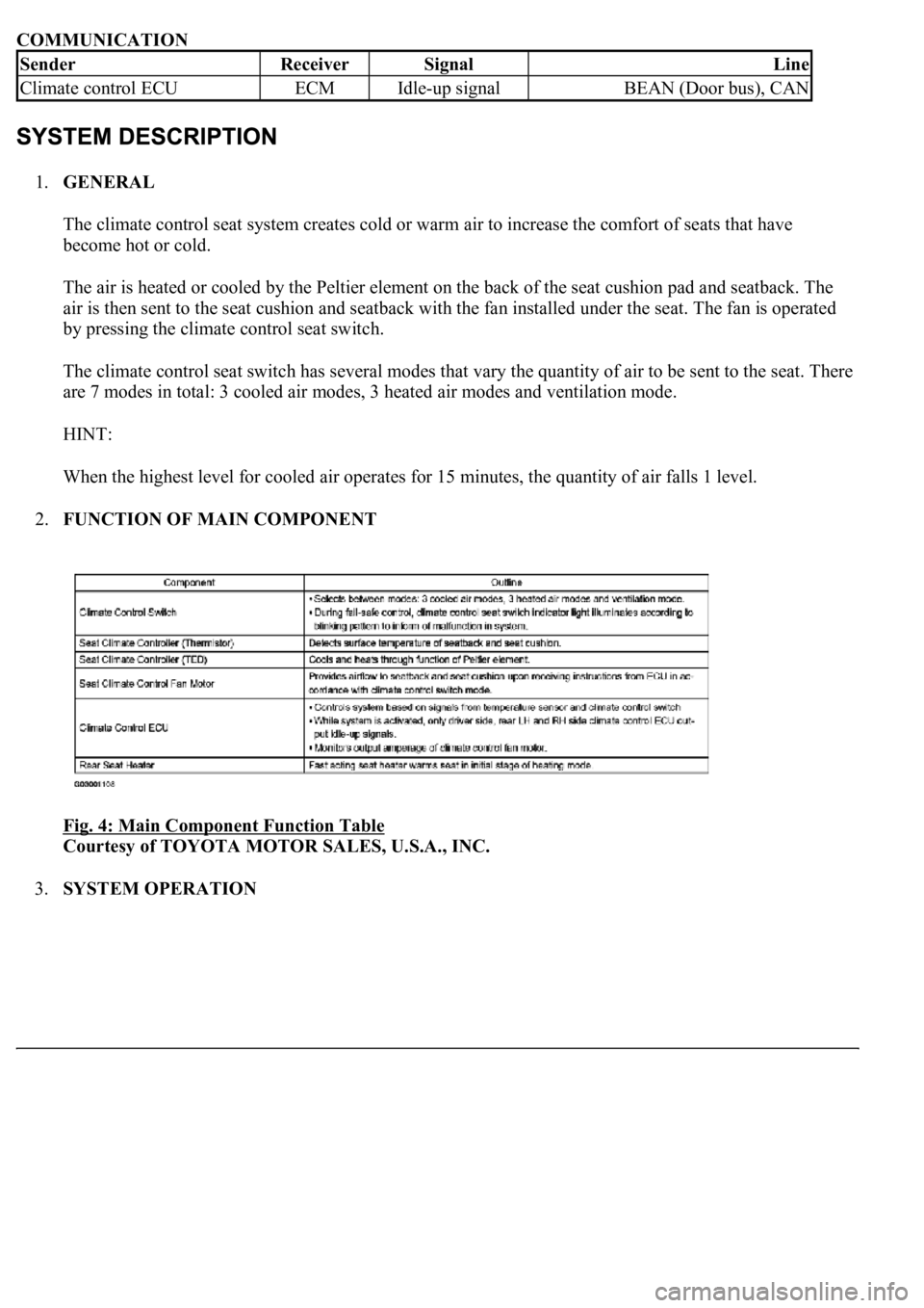
COMMUNICATION
1.GENERAL
The climate control seat system creates cold or warm air to increase the comfort of seats that have
become hot or cold.
The air is heated or cooled by the Peltier element on the back of the seat cushion pad and seatback. The
air is then sent to the seat cushion and seatback with the fan installed under the seat. The fan is operated
by pressing the climate control seat switch.
The climate control seat switch has several modes that vary the quantity of air to be sent to the seat. There
are 7 modes in total: 3 cooled air modes, 3 heated air modes and ventilation mode.
HINT:
When the highest level for cooled air operates for 15 minutes, the quantity of air falls 1 level.
2.FUNCTION OF MAIN COMPONENT
Fig. 4: Main Component Function Table
Courtesy of TOYOTA MOTOR SALES, U.S.A., INC.
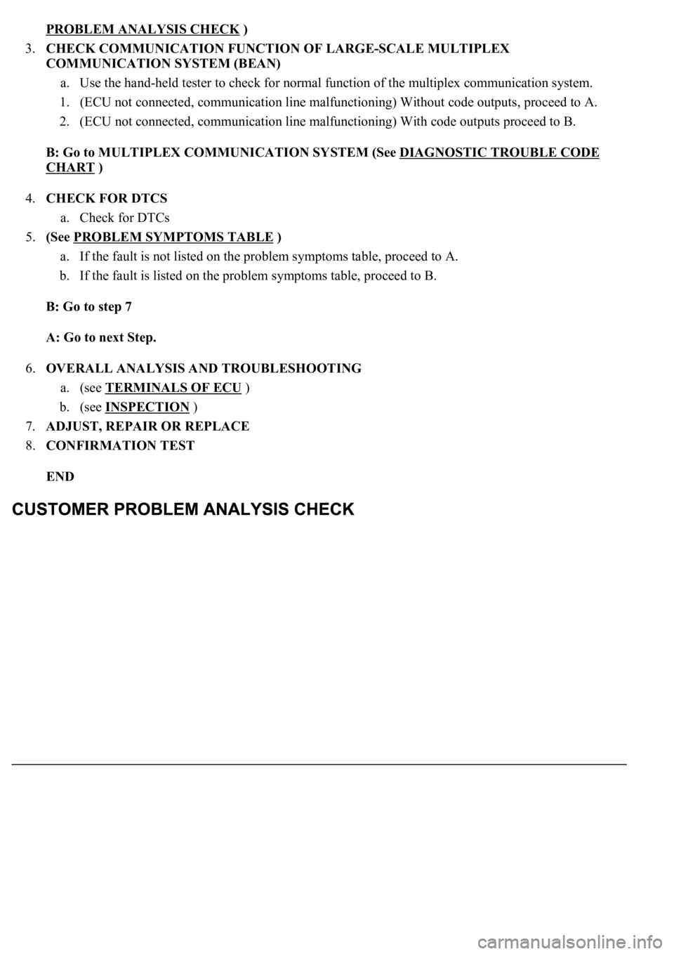
3.SYSTEM OPERATION
SenderReceiverSignalLine
Climate control ECUECMIdle-up signalBEAN (Door bus), CAN
Page 1592 of 4500
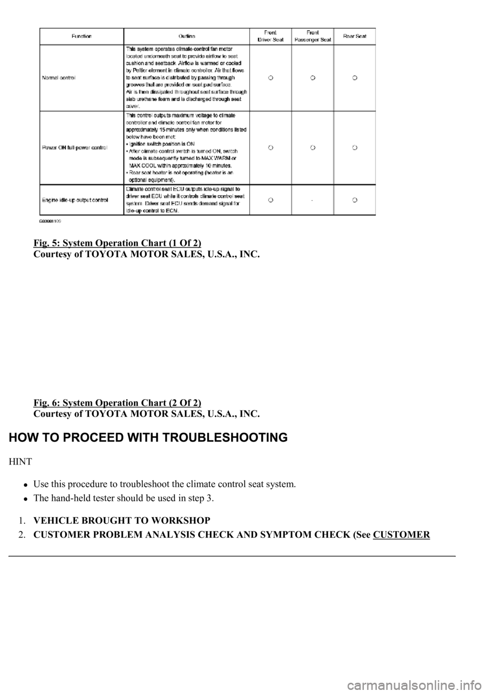
Fig. 5: System Operation Chart (1 Of 2)
Courtesy of TOYOTA MOTOR SALES, U.S.A., INC.
Fig. 6: System Operation Chart (2 Of 2)
Courtesy of TOYOTA MOTOR SALES, U.S.A., INC.
HINT
Use this procedure to troubleshoot the climate control seat system.
The hand-held tester should be used in step 3.
1.VEHICLE BROUGHT TO WORKSHOP
2.CUSTOMER PROBLEM ANALYSIS CHECK AND SYMPTOM CHECK (See CUSTOMER
Page 1593 of 4500
PROBLEM ANALYSIS CHECK )
3.CHECK COMMUNICATION FUNCTION OF LARGE-SCALE MULTIPLEX
COMMUNICATION SYSTEM (BEAN)
a. Use the hand-held tester to check for normal function of the multiplex communication system.
1. (ECU not connected, communication line malfunctioning) Without code outputs, proceed to A.
2. (ECU not connected, communication line malfunctioning) With code outputs proceed to B.
B: Go to MULTIPLEX COMMUNICATION SYSTEM (See DIAGNOSTIC TROUBLE CODE
CHART )
4.CHECK FOR DTCS
a. Check for DTCs
5.(See PROBLEM SYMPTOMS TABLE
)
a. If the fault is not listed on the problem symptoms table, proceed to A.
b. If the fault is listed on the problem symptoms table, proceed to B.
B: Go to step 7
A: Go to next Step.
6.OVERALL ANALYSIS AND TROUBLESHOOTING
a. (see TERMINALS OF ECU
)
b. (see INSPECTION
)
7.ADJUST, REPAIR OR REPLACE
8.CONFIRMATION TEST
END
Page 1594 of 4500
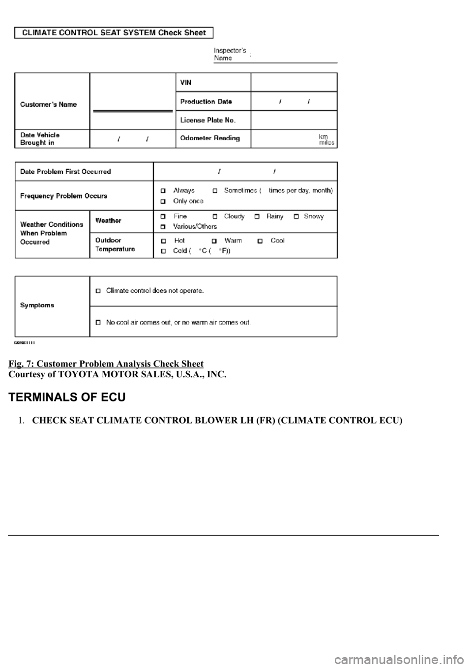
Fig. 7: Customer Problem Analysis Check Sheet
Courtesy of TOYOTA MOTOR SALES, U.S.A., INC.
1.CHECK SEAT CLIMATE CONTROL BLOWER LH (FR) (CLIMATE CONTROL ECU)
Page 1595 of 4500

Fig. 8: Identifying Terminals Of Climate Control ECU - LH (FR)
Courtesy of TOYOTA MOTOR SALES, U.S.A., INC.
a. Disconnect the C20 and S48 blower connectors.
b. Measure the voltage and resistance of the wire harness side connectors.
Standard:
TERMINAL DESCRIPTION AND SPECIFIED CONDITION
Symbols
(Terminal
No.)Wiring
ColorTerminal
DescriptionConditionSpecified
Condition
E (C20 - 8) -
Body groundW-B -
Body
ground
GroundAlwaysBelow 1 ohms
IG (C20 -7) -
Body groundB - Body
groundPower sourceIgnition switch ON10 to 14 V
V5 (C20 - 13)
- VG (C20 - 9)GR-R - LPower supply for
volume switchAlways5 kohms
VS (C20 - 12)
- VG (20 - 9)R-B - LVolume switch signalTurn volume switch: Max0 ohms --> 5
kohms
TB5 (C20 - 4)
- TBS (20 - 3)L-Y -
BR-WSeatback temperature
sensorSeatback temperature: 10°C --
> 30°C (50°F --> 86°F)Approx. 3.7
kohms -->
Approx. 1.7
Page 1596 of 4500

HINT:
*1: For vehicles with a rear seat heater system
*2: For vehicles with a rear seat climate control system
If the result is not as specified, there may be a malfunction on the wire harness side.
c. Reconnect the C20 and S48 blower connectors.
d. Measure the voltage of the connectors.
Standard:
TERMINAL DESCRIPTION AND SPECIFIED CONDITION
If the result is not as specified, the ECU ma
y have a malfunction.
kohms
TC5 (S48 - 2)
- TCS (S48 -
1)
B - BSeat cushion
temperature sensorSeatback temperature: 10°C --
> 30°C (50°F --> 86°F)
Approx. 3.7
kohms -->
Approx. 1.7
kohms
DSID (C20 -
6) - Body
groundP - Body
ground
Rear seat heater
switch*1 Rear seat
climate control
switch*2Ignition switch: ON Turn rear
seat heater switch*1 or rear
seat climate control switch*2
OFF --> ON
0 V --> 10 to 14
V
Symbols
(Terminal No.)Wiring
ColorTerminal DescriptionConditionSpecified
Condition
IND (C20-5) -
Body groundY-R - Body
groundClimate control switch
indicatorIgnition switch: ON Turn
climate control switch: OFF -->
ON0 V --> 10 to
14 V
IDL (C20-10) -
Body groundW - Body
groundEngine idle-up signal
Ignition switch: ON Turn
climate control switch: OFF -->
ON10 to 14 V --
> 0 V
TDB+ (C20-14) -
Body groundLG-B -
Body
groundPower supply for seatback
Peltier element (WARM)Ignition switch: ON Turn
climate control switch: OFF -->
Max. WARM0 V --> 10 to
14 V
TDB- (C20-1) -
Body groundB - Body
groundPower supply for seatback
Peltier element (COOL)Ignition switch: ON Turn
climate control switch: OFF -->
Max. COOL0 V --> 10 to
14 V
TDC+ (S48-3) -
Body groundL - Body
groundPower supply for seat
cushion Peltier element
(WARM)Ignition switch: ON Turn
climate control switch: OFF -->
Max. WARM0 V --> 10 to
14 V
TDC- (S48-6) -
Body groundY - Body
groundPower supply for seat
cushion Peltier element
(COOL)Ignition switch: ON Turn
climate control switch: OFF -->
Max. COOL0 V --> 10 to
14 V
Page 1597 of 4500
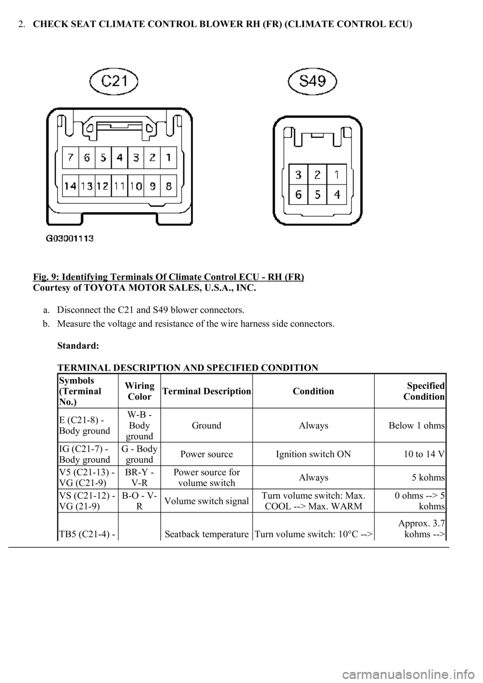
2.CHECK SEAT CLIMATE CONTROL BLOWER RH (FR) (CLIMATE CONTROL ECU)
Fig. 9: Identifying Terminals Of Climate Control ECU
- RH (FR)
Courtesy of TOYOTA MOTOR SALES, U.S.A., INC.
a. Disconnect the C21 and S49 blower connectors.
b. Measure the voltage and resistance of the wire harness side connectors.
Standard:
TERMINAL DESCRIPTION AND SPECIFIED CONDITION
Symbols
(Terminal
No.)Wiring
ColorTerminal DescriptionConditionSpecified
Condition
E (C21-8) -
Body groundW-B -
Body
ground
GroundAlwaysBelow 1 ohms
IG (C21-7) -
Body groundG - Body
groundPower sourceIgnition switch ON10 to 14 V
V5 (C21-13) -
VG (C21-9)BR-Y -
V-RPower source for
volume switchAlways5 kohms
VS (C21-12) -
VG (21-9)B-O - V-
RVolume switch signalTurn volume switch: Max.
COOL --> Max. WARM0 ohms --> 5
kohms
TB5 (C21-4) - Seatback temperature Turn volume switch: 10°C -->
Approx. 3.7
kohms -->
Page 1598 of 4500

HINT:
*1: For vehicles with a rear seat heater system
*2: For vehicles with a rear seat climate control system
If the result is not as specified, there may be a malfunction on the wire harness side.
c. Reconnect the C21 and S49 blower connectors.
d. Measure the voltage of the connector.
Standard:
TERMINAL DESCRIPTION AND SPECIFIED CONDITION
If the result is not as specified, the ECU may have a malfunction.
3.SEAT CLIMATE CONTROL BLOWER LH (RR) (CLIMATE CONTROL ECU)
TBS (C21-3)G-Y - Rsensor30°C (50°F --> 86°F)Approx. 1.7
kohms
TC5 (S49-2) -
TCS (S49-1)B -BSeat cushion
temperature sensorTurn the volume switch: 10°C
--> 30°C (50°F --> 86°F)
Approx. 3.7
kohms -->
Approx. 1.7
kohms
DSID (C21-6)
- Body groundGR -
Body
groundRear seat heater
switch*1 Rear seat
climate control
switch*2Ignition switch: ON Turn rear
seat heater switch*1 or rear
seat climate control switch*2
OFF --> ON
0 V --> 10 to 14
V
Symbols
(Terminal No.)Wiring
ColorTerminal DescriptionConditionSpecified
Condition
IND (C21-5) -
Body groundY-B - Body
groundClimate control switch
indicatorIgnition switch: ON Turn
climate control switch: OFF -->
ON0 V --> 10 to
14 V
TDB+ (C21-14) -
Body groundLG-B -
Body
groundPower supply for seatback
Peltier element (WARM)Ignition switch: ON Turn
climate control switch: OFF -->
Max. WARM0 V --> 10 to
14 V
TDB- (C21-1) -
Body groundB - Body
groundPower supply for seatback
Peltier element (COOL)Ignition switch: ON Turn
climate control switch: OFF -->
Max. COOL0 V --> 10 to
14 V
TDC+ (S49-3) -
Body groundL - Body
groundPower supply for seat
cushion Peltier element
(WARM)Ignition switch: ON Turn
climate control switch: OFF -->
Max. WARM0 V --> 10 to
14 V
TDC- (S49-6) -
Body groundY - Body
groundPower supply for seat
cushion Peltier element
(COOL)Ignition switch: ON Turn
climate control switch: OFF -->
Max. COOL0 V --> 10 to
14 V
Page 1599 of 4500

Fig. 10: Identifying Terminals Of Climate Control ECU - LH (RR)
Courtesy of TOYOTA MOTOR SALES, U.S.A., INC.
a. Disconnect the C27 and C28 blower connectors.
b. Measure the voltage and resistance of the wire harness side connectors.
Standard:
TERMINAL DESCRIPTION AND SPECIFIED CONDITION
If the result is not as specified, there ma
y be a malfunction on the wire harness side.
Symbols
(Terminal No.)Wiring
ColorTerminal
DescriptionConditionSpecified Condition
GND (C27-11) -
Body groundW-B -
Body
ground
GroundAlwaysBelow 1 ohms
IG (C27-10) -
Body groundR-B - Body
groundPower sourceIgnition switch ON10 to 14 V
SW (C27-8) -
Body groundL - Body
groundClimate control
switchTurn the climate control
switch ONBelow 1 ohms
V5 (C27-18) -
VG (C27-16)Y-R - PVolume switchAlways5 kohms
VS (C27-17) -
VG (C27-16)GR-R - PVolume switch
signalRear left volume switch:
Max. COOL --> Max.
WARM
0 ohms --> 5 kohms
TB5 (C28-7) -
TBS (C28-16)G-Y - RSeatback
temperatureSeatback temperature: 10°
C --> 30°C (50°F --> 86°F)Approx. 3.7 kohms -
-> Approx. 1.7
kohms
H5 (C28-5) - HS
(C28-14)L-B - Y-RSeat cushion
temperature sensorSeat cushion temperature:
10°C --> 30°C (50°F -->
86°F)Approx. 3.7 kohms -
-> Approx. 1.7
kohms
TC5 (C28-6) -
TCS (C28-15)BR-R - P-
BHeater
temperature sensorHeater temperature: 10°C -
-> 30°C (50°F --> 86°F)Approx. 3.7 kohms -
-> Approx. 1.7
kohms
Page 1600 of 4500
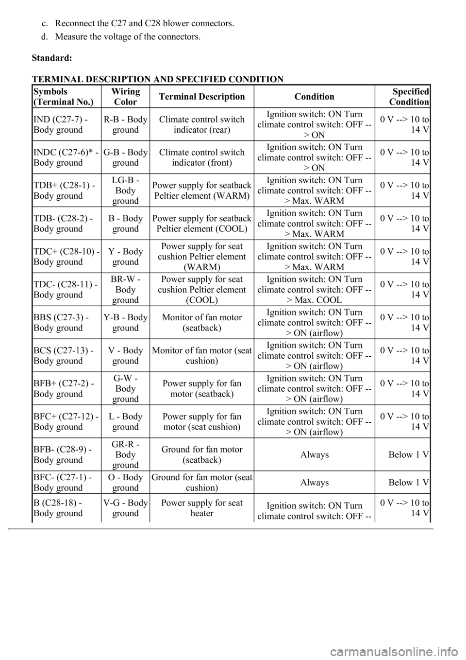
c. Reconnect the C27 and C28 blower connectors.
d. Measure the voltage of the connectors.
Standard:
TERMINAL DESCRIPTION AND SPECIFIED CONDITION
Symbols
(Terminal No.)Wiring
ColorTerminal DescriptionConditionSpecified
Condition
IND (C27-7) -
Body groundR-B - Body
groundClimate control switch
indicator (rear)Ignition switch: ON Turn
climate control switch: OFF --
> ON0 V --> 10 to
14 V
INDC (C27-6)* -
Body groundG-B - Body
groundClimate control switch
indicator (front)Ignition switch: ON Turn
climate control switch: OFF --
> ON0 V --> 10 to
14 V
TDB+ (C28-1) -
Body groundLG-B -
Body
groundPower supply for seatback
Peltier element (WARM)Ignition switch: ON Turn
climate control switch: OFF --
> Max. WARM0 V --> 10 to
14 V
TDB- (C28-2) -
Body groundB - Body
groundPower supply for seatback
Peltier element (COOL)Ignition switch: ON Turn
climate control switch: OFF --
> Max. WARM0 V --> 10 to
14 V
TDC+ (C28-10) -
Body groundY - Body
groundPower supply for seat
cushion Peltier element
(WARM)Ignition switch: ON Turn
climate control switch: OFF --
> Max. WARM0 V --> 10 to
14 V
TDC- (C28-11) -
Body groundBR-W -
Body
groundPower supply for seat
cushion Peltier element
(COOL)Ignition switch: ON Turn
climate control switch: OFF --
> Max. COOL0 V --> 10 to
14 V
BBS (C27-3) -
Body groundY-B - Body
groundMonitor of fan motor
(seatback)Ignition switch: ON Turn
climate control switch: OFF --
> ON (airflow)0 V --> 10 to
14 V
BCS (C27-13) -
Body groundV - Body
groundMonitor of fan motor (seat
cushion)Ignition switch: ON Turn
climate control switch: OFF --
> ON (airflow)0 V --> 10 to
14 V
BFB+ (C27-2) -
Body groundG-W -
Body
groundPower supply for fan
motor (seatback)Ignition switch: ON Turn
climate control switch: OFF --
> ON (airflow)0 V --> 10 to
14 V
BFC+ (C27-12) -
Body groundL - Body
groundPower supply for fan
motor (seat cushion)Ignition switch: ON Turn
climate control switch: OFF --
> ON (airflow)0 V --> 10 to
14 V
BFB- (C28-9) -
Body groundGR-R -
Body
groundGround for fan motor
(seatback)AlwaysBelow 1 V
BFC- (C27-1) -
Body groundO - Body
groundGround for fan motor (seat
cushion)AlwaysBelow 1 V
B (C28-18) -
Body groundV-G - Body
groundPower supply for seat
heaterIgnition switch: ON Turn
climate control switch: OFF --0 V --> 10 to
14 V